Making the ball play / pre-programmed system
OK, so your Ardiono blinks, that was Hello World!
Servo motor
Now we will hookup a servo motor and instruct it to behave a certain way.
Servos have to receive high-pulse control signals at regular intervals to keep turning. If the signal stops, so does the servo.
Once your sketch uses the Servo library to set up the signal, it can move on to other code, like delays, checking sensors, etc. Meanwhile, the servo keeps turning because the Servo library keeps running in the background. It regularly interrupts the execution of other code to initiate those high pulses, doing it so quickly that it’s practically unnoticeable.
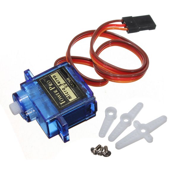
This is a servo, a very small one
An ordinary DC motor has two hookup wires and simply turns continuously when power is applied. If you want it to spin in the opposite direction, you'll need to reverse the power. And if you want to know how far it has turned, you'll need to devise a way to measure that.
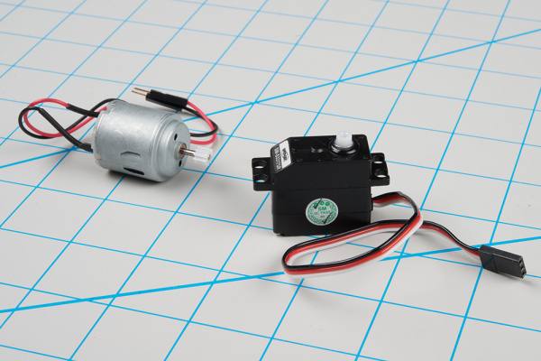
RC servos are reasonably standardized - they are all a similar shape, with mounting flanges at each end, available in graduated sizes, from "ultra-nano" to "giant". Servos often come with multiple attachments, such as wheels or levers, known as “horns”, than can be attached to the shaft, to fit the device they are operating.
Hookup
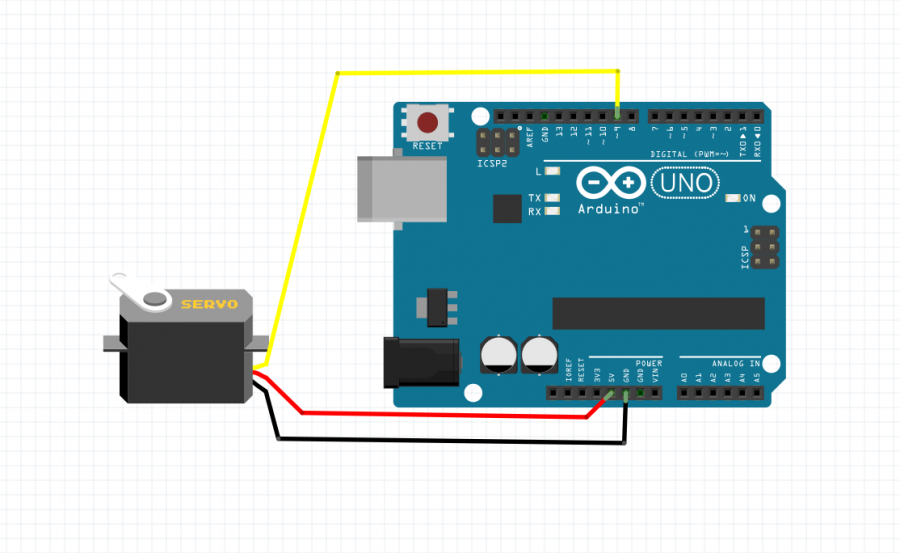
The servo has 3 wires, we need to connect them all to the arduino. One thing that can be confusing is that the wiring color code isn't always consistent -- there are several color codes at play. The good news is that the pins are usually in the same order, just that the colors are different.
If you're in doubt about your color scheme, check the documentation -- don't plug it in backwards!
red is for 5V
you will find it easy to plug one end of a jumper wire inside the connectors of the servo motor, and the other end to the corresponding pin of the Arduino make sure you use corresponding colors for the jumpers, in bigger setups messy wire can cause you more time to debug
black is for GND
to GND of the Arduino
Regardless of how you're powering them, it's worth noting that the current consumed by the motor increases as the mechanical loading increases. A small servo with nothing attached to the shaft might draw 10 mA, while a large one turning a heavy lever might draw an Ampere or more! If your power supply isn't up to the task, a straining or stalled servo can cause the supply to sag, which may have other unpredictable repercussions, such as causing microcontrollers to reset.
and orange is for signal
signal is going into the pin of the Arduino we will use to control the servo motor
We will look for a pin that has a wave next to the number ( look at the Arduino board). Those pins are able to output Pulse Width Modulation (PWM) is a fancy term for describing a type of digital signal. Pulse width modulation is used in a variety of applications including sophisticated control circuitry. Also in our case control the servo motor. The control wire is used to send this pulse.
This control signal is a specific type of pulse train. The pulses occur at a 20 mSec (50 Hz) interval, and vary between 1 and 2 mSec in width. The Pulse Width Modulation hardware available on a microcontroller is a great way to generate servo control signals.
Common servos rotate over a range of 90° as the pulses vary between 1 and 2 mSec -- they should be at the center of their mechanical range when the pulse is 1.5 mSec.

For more info how servos work look here [[1]]
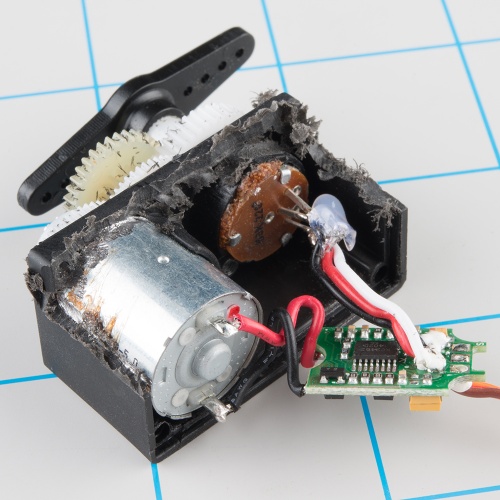
Inside
Internally, the mechanism of a servo motor uses a potentiometer attached to the rotating shaft to sense the position. It measures the width of the incoming pulse and applies current to the motor to turn the shaft, until the potentiometer indicates that the position corresponds to the incoming pulse width. This is a form of feedback control. The motor has received the desired position from the pulse width, and the actual shaft position is fed back to the circuit via the potentiometer. It compares the desired value to the actual value and drives the motor in the direction that causes actual to match desired.
We will use an example code to see if our servos work
Sweep
Now with knowing where the examples are located, find a servo example sketch called sweep.
you should have a code that looks like this
/* Sweep
 by BARRAGAN <http://barraganstudio.com>
 This example code is in the public domain.

 modified 8 Nov 2013
 by Scott Fitzgerald
 http://www.arduino.cc/en/Tutorial/Sweep
*/

#include <Servo.h>

Servo myservo;  // create servo object to control a servo
// twelve servo objects can be created on most boards

int pos = 0;    // variable to store the servo position

void setup() {
  myservo.attach(9);  // attaches the servo on pin 9 to the servo object
}

void loop() {
  for (pos = 0; pos <= 180; pos += 1) { // goes from 0 degrees to 180 degrees
    // in steps of 1 degree
    myservo.write(pos);              // tell servo to go to position in variable 'pos'
    delay(15);                       // waits 15ms for the servo to reach the position
  }
  for (pos = 180; pos >= 0; pos -= 1) { // goes from 180 degrees to 0 degrees
    myservo.write(pos);              // tell servo to go to position in variable 'pos'
    delay(15);                       // waits 15ms for the servo to reach the position
  }
}
Let's upload the sketch to the board
Observe the motor---->sweeping?
Knob
Great,
let us include another agent into the servo situation.
A potentiometer to exercise some external control
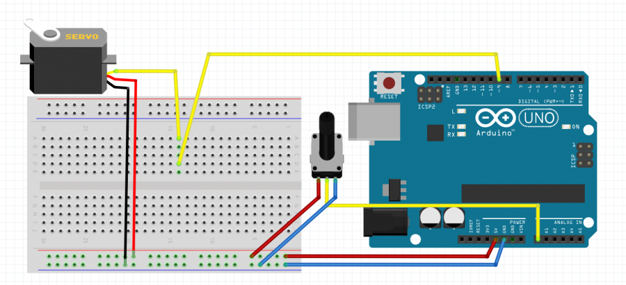
/*
 Controlling a servo position using a potentiometer (variable resistor)
 by Michal Rinott <http://people.interaction-ivrea.it/m.rinott>

 modified on 8 Nov 2013
 by Scott Fitzgerald
 http://www.arduino.cc/en/Tutorial/Knob
*/

#include <Servo.h>

Servo myservo;  // create servo object to control a servo

int potpin = 0;  // analog pin used to connect the potentiometer
int val;    // variable to read the value from the analog pin

void setup() {
  myservo.attach(9);  // attaches the servo on pin 9 to the servo object
}

void loop() {
  val = analogRead(potpin);            // reads the value of the potentiometer (value between 0 and 1023)
  val = map(val, 0, 1023, 0, 180);     // scale it to use it with the servo (value between 0 and 180)
  myservo.write(val);                  // sets the servo position according to the scaled value
  delay(15);                           // waits for the servo to get there
}
