Difference between revisions of "Make a drawing machine and a Grabber robot with Arduino"
(Created page with "=Now we add two servos and two pots= 1000 px <syntaxhighlight lang=c style="border:3px dashed blue"> #include <Servo.h> Servo myse...") |
|||
| (One intermediate revision by the same user not shown) | |||
| Line 1: | Line 1: | ||
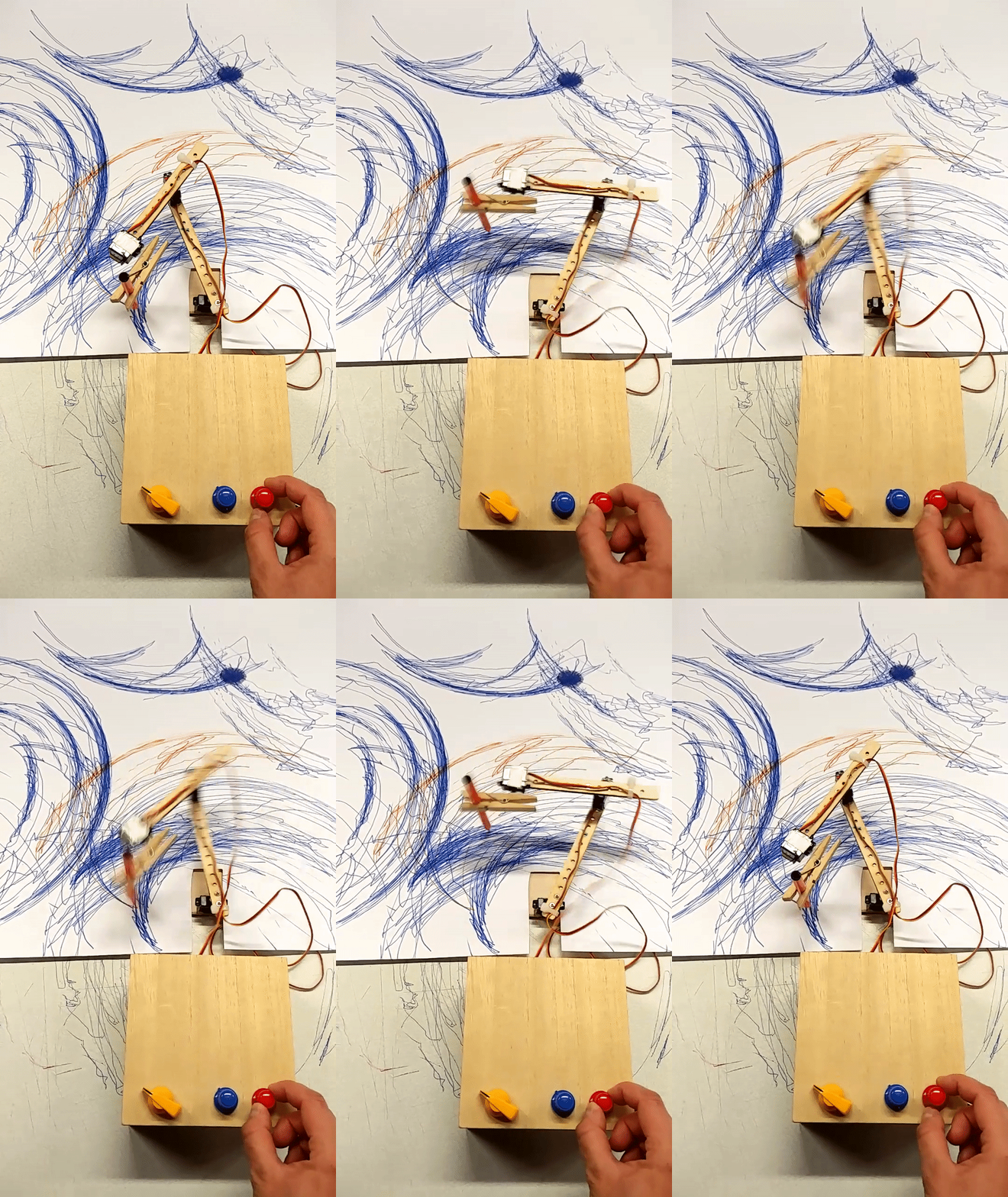
| + | [[File:Drawingmachine01.gif]] <br> | ||
=Now we add two servos and two pots= | =Now we add two servos and two pots= | ||
Revision as of 20:20, 7 October 2018
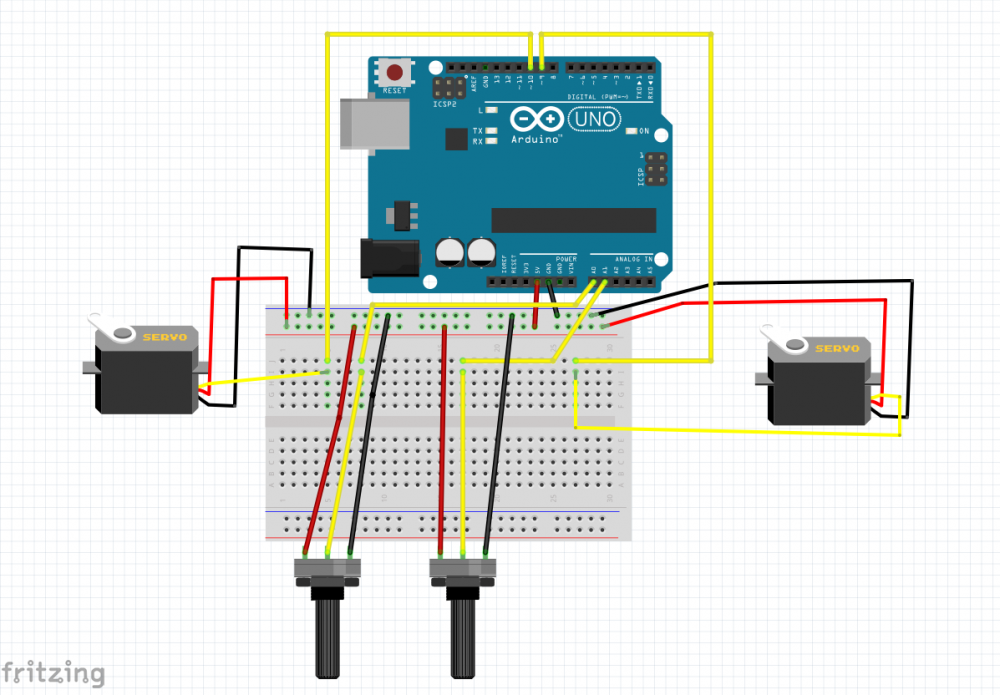
Now we add two servos and two pots
#include <Servo.h>

Servo myservo1;  // create servo object to control a servo
Servo myservo2;  // create servo object to control a second servo

int pot1 = 0;  // analog pin used to connect one potentiometer
int pot2 = 1; // analog pin used to connect another potentiometer

int val1 = 0;    // variable to read the value from one analog pin
int val2 = 0;    // variable to read the value from the other analog pin

void setup() {
  //Serial.begin(9600);
  myservo1.attach(9);  // attaches one servo on pin 9 to the servo object
  myservo2.attach(10);  // attaches the other servo on pin 10 to the servo object
}

void loop() {
  val1 = analogRead(pot1);            // reads the value of one potentiometer (value between 0 and 1023)
  val1 = map(val1, 0, 1023, 0, 85);     // scale it to use it with the servo (value between 0 and 85)
  myservo1.write(val1); // sets the first servo position according to the scaled value
  //Serial.println(val1);
  delay(25); // waits for the servo to get there

  val2 = analogRead(pot2);            // reads the value of the second potentiometer (value between 0 and 1023)
  val2 = map(val2, 0, 1023, 0, 85);     // scale it to use it with the servo (value between 0 and 85)
  myservo2.write(val2); // sets the second servo position according to the scaled value
  //Serial.println(val2);
  delay(25); // waits for the servo to get there

}
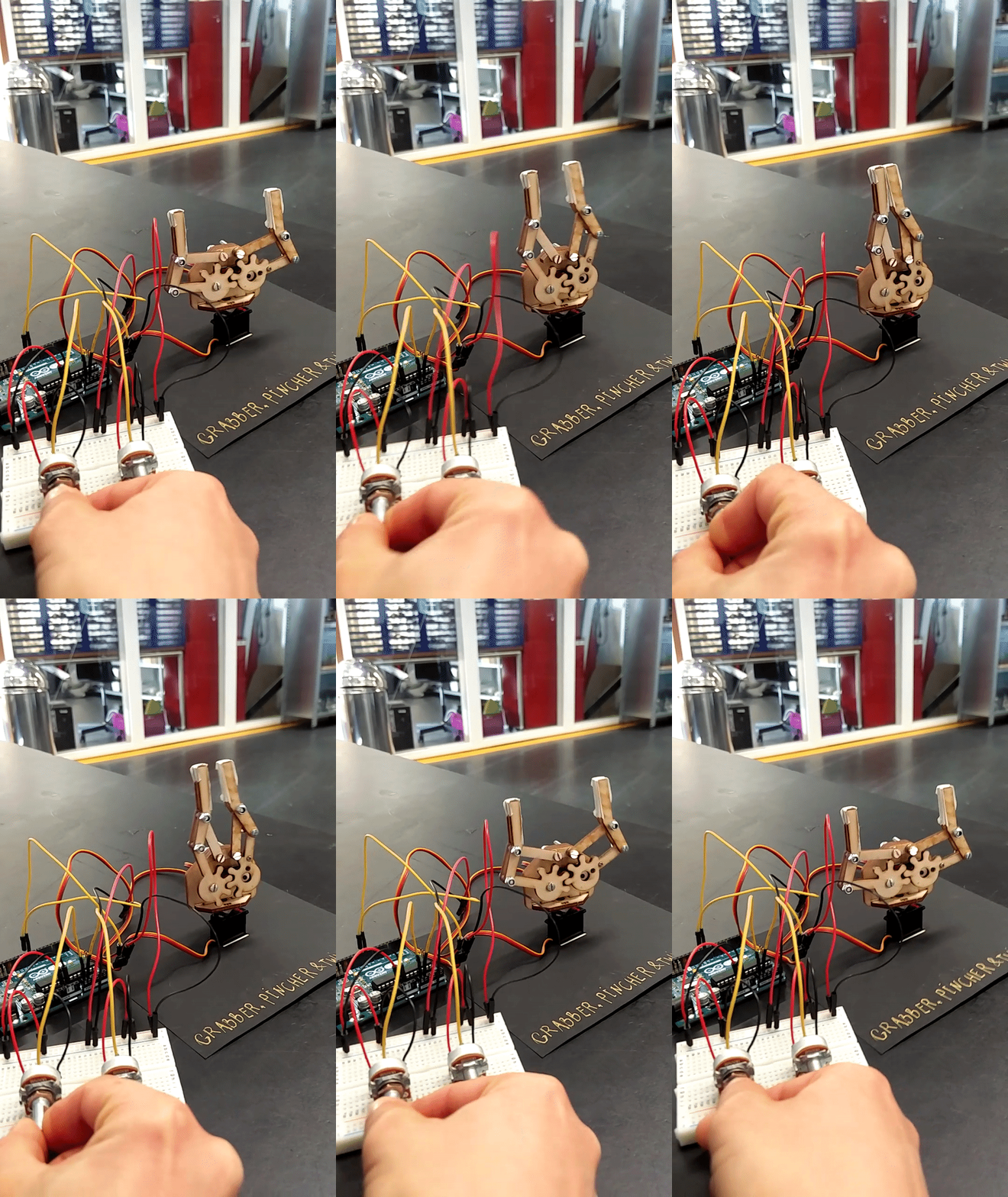
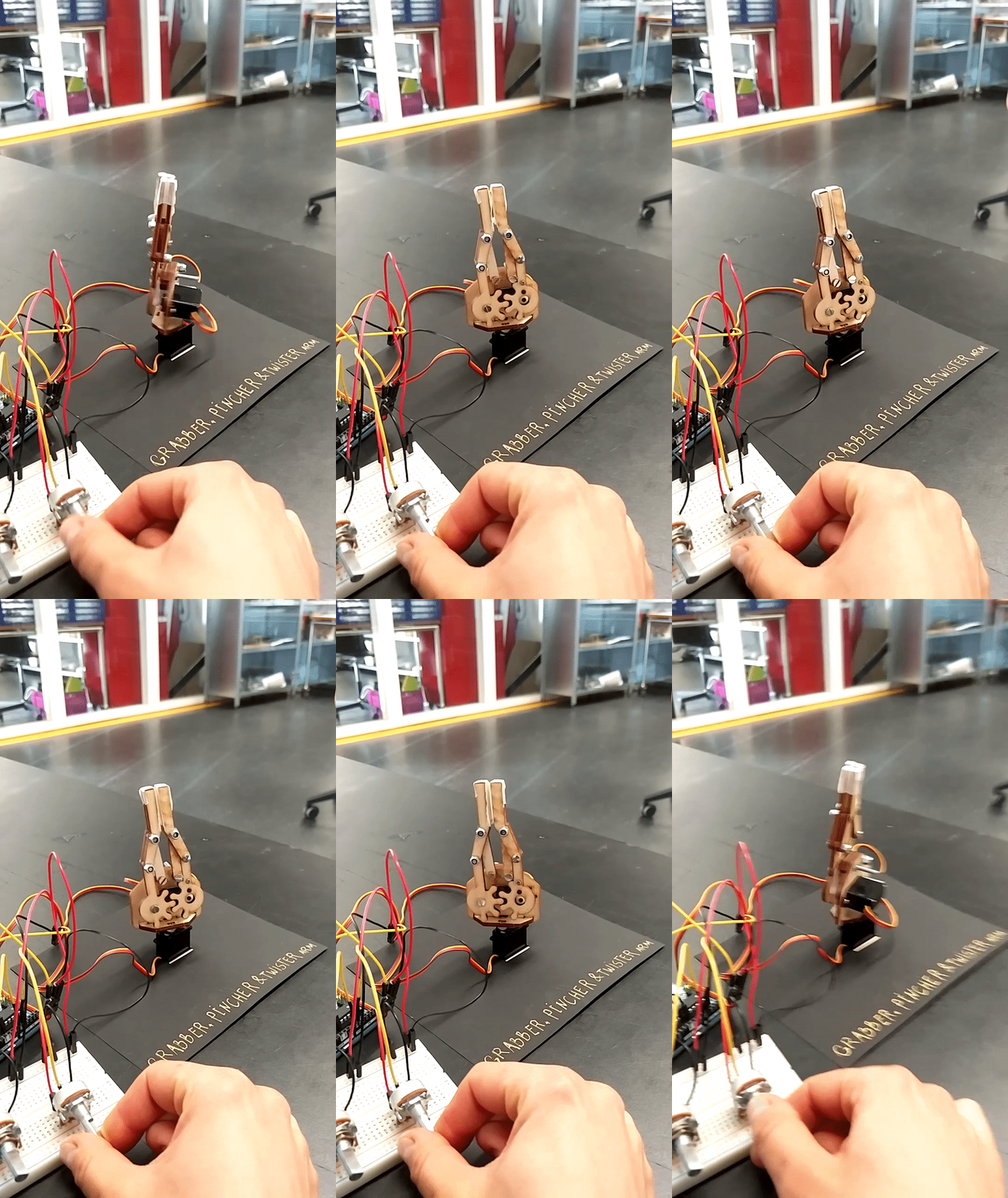
Using the servos to animate a Grabber, Pincher and Twister Arm
Get the file to laser cut File:ServoArm01 grab.pdf
Open .pdf with Illustrator and examine the file.
Check here lasercutting instructions ------> making vector files for lasercutting in illustrator aka making use of your adobe
Basic mechanisms
briefly some basic mechanisms
Levers
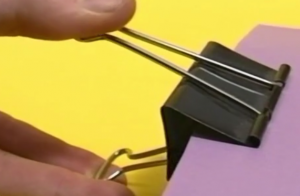
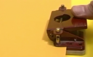
a lever is a rigid object with pivot point used to multiply the mechanical force of an object
it has input – pivot point-output
examples: seesaw hammer when removing nails crowbar also
Cranks
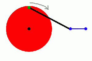
A crank is simply an off-center connection that provides energy to (or takes energy from) a rotating wheel.
Slider crank mechanisms
he crank slider turns a circular motion in an oscillating movement and a vertical movement. The larger the distance between the wheel and the plane green brown, the lower the oscillation of the highest point of the red stick
Crankshaft
The cam piston transforms a circular motion in a vertical movement. The larger the diameter of the wheel, the greater the vertical stroke of the red stick.
Linkages
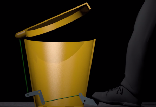
we can use extra motion ( for exmple from a crank) to add extra movement
A linkage can be made from levers, cranks and connecting elements. They are use to change direction or amount of motion
Cams
Cams generally do the opposite job to cranks: they turn rotary motion into reciprocating motion.
Eccentric cam
The eccentric cam transforms a circular motion in a vertical movement. the vertical excursion of the red stick changes as a function of the varying diameter of the cam.
Jumping Cam
The shape of the cam creates a jump during the movement of the red stick. In this way can produce abrupt and sudden movements.
Shafts
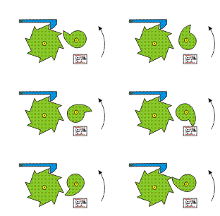
Ratchets
can be used to give intermittent or stepped motion. Also used to give rotation in one direction only
The cam rotates the large wheel of an eighth for each revolution. The blue slider prevents the large wheel can turn in the opposite.
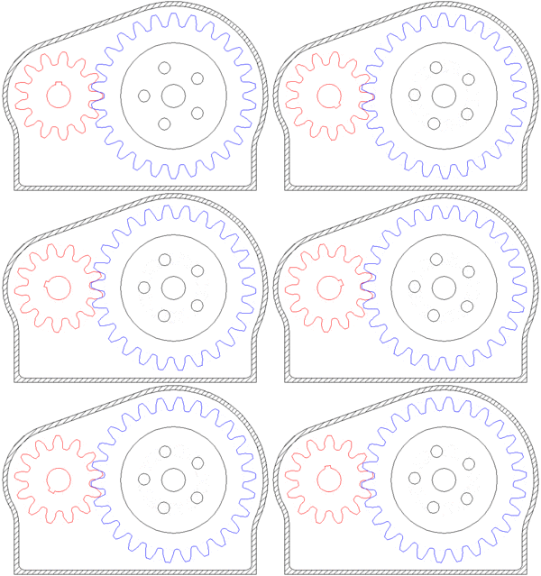
Gearing
A gear or cogwheel is a rotating machine part having cut teeth, or cogs, which mesh with another toothed part to transmit torque.
Geared devices can change the speed and power delivered.
GEAR RATIO
two gears, one half as big as the other, have a gear ratio of 2:1. The smaller gear has to spin twice to cover the same distance covered when the larger gear spins once.
Drives
A drive is a method of connection rotation shafts together
the drive can involve gearing, changing direction or rotation of the shafts.
A bike chain is a POSITIVE DRIVE ...it cannot slip ( it is kept locked to the sprocket wheel ) , while wheels slip if they are under resistance ( break) and they stop turning, that is FRICTION, pulleys also work by friction.
