Difference between revisions of "About Arduino"
| (37 intermediate revisions by 2 users not shown) | |||
| Line 1: | Line 1: | ||
| − | + | =What is an Arduino = | |
| + | [[File:Uno_board.png|350px|thumb|The Arduino board]] | ||
| + | [[File:ide.png|350px|thumb|The Arduino IDE]] | ||
| + | From the Wikipedia article on Arduino we read<ref>https://en.wikipedia.org/wiki/Arduino</ref>: | ||
| + | <pre style="white-space: pre-wrap; white-space: -moz-pre-wrap; white-space: -pre-wrap; white-space: -o-pre-wrap; word-wrap: break-word;"> | ||
| + | Arduino is an open-source computer hardware and software company, project and user community that designs and manufactures kits for building digital devices and interactive objects that can sense and control the physical world. Arduino boards may be purchased preassembled, or as do-it-yourself kits; at the same time, the hardware design information is available for those who would like to assemble an Arduino from scratch. | ||
| + | </pre> | ||
| + | Arduino is an open source physical computing platform based on a simple input/output (I/O) board and a development environment that implements the Processing language. Arduino can be used to develop standalone interactive objects or can be connected to software on your computer. These types of work are usually called [[Physical Computing|Physical Computing]].<br> | ||
| + | Physical Computing creates interactive systems by using electronics. The purpose is to prototype new materials for designers and artists. | ||
| + | <br> | ||
| + | ===What makes an Arduino?=== | ||
| + | Arduino is composed of two major parts: the Arduino board, which is the piece of hardware you work on when you build your objects; and the Arduino IDE, the piece of software you run on your computer. You use the IDE to create a sketch (a little computer program) that you upload to the Arduino board. The sketch tells the board what to do. | ||
| + | In the meantime, [https://www.arduino.cc/ HERE] you can find anything about Arduino, including download the software. | ||
| + | <br> | ||
| + | In essence Arduino is ''just another'' μController development board. The main purpose of such a μController development board is to make it easy for developers to evaluate the functions of, or create a quick prototype with, a certain type of μController. μControllers come in al sorts of tastes and sizes hence there are many different flavours of μController development boards as well. Do, for example, a Google search on [https://www.google.nl/search?hl=en&site=imghp&tbm=isch&source=hp&biw=1366&bih=679&q=microcontroller+development+board microcontroller development board]. You will see an abundance of different different platforms and most likely you will find some Arduino flavours there as well. | ||
| + | |||
| + | ===A bit of Arduino history=== | ||
| + | The project is based on a family of microcontroller board designs manufactured primarily by SmartProjects in Italy, and also by several other vendors, using various 8-bit Atmel AVR microcontrollers or 32-bit Atmel ARM processors. These systems provide sets of digital and analog I/O pins that can be interfaced to various extension boards and other circuits. The boards feature serial communications interfaces, including USB on some models, for loading programs from personal computers. For programming the microcontrollers, the Arduino platform provides an integrated development environment (IDE) based on the Processing project, which includes support for C and C++ programming languages. | ||
| − | + | The first Arduino was introduced in 2005. The project leaders sought to provide an inexpensive and easy way for hobbyists, students, and professionals to create devices that interact with their environment using sensors and actuators. Common examples for beginner hobbyists include simple robots, thermostats and motion detectors. | |
| − | + | </pre> | |
| − | |||
| − | |||
| − | |||
| − | |||
| − | < | ||
| − | |||
| − | |||
| − | + | ==What do you use Arduino for?== | |
| − | + | Arduino is involved in lots of works. Here are some examples: | |
| − | [[ | + | *[https://m-h-z.net/rippler/ Sound sculptures] |
| + | *[http://www.susannahertrich.com/work/jacobsons-fabulous-olfactometer/ Sensing pollution] | ||
| + | *[http://vtol.cc/filter/works/you-me-and-all-these-machines Performance / Microphone manipulation] | ||
| + | *[https://vimeo.com/241028491 Light swarm] | ||
| + | *[http://www.mkontopoulos.com/portfolio/machines-that-almost-fall-over/ Machines that almost fall over] | ||
| + | *[http://vtol.cc/filter/works/antenna Mom, I hit a man] | ||
| + | *[http://katihyyppa.com/forbidden-fruit-machine/ Forbidden fruit machine] | ||
| + | *[http://katihyyppa.com/as-light-goes-by/ As light goes by] | ||
| + | *[https://vimeo.com/236594080 Instant messanging?] | ||
| + | *[https://vimeo.com/116904791 String fountain] | ||
| + | *[https://vimeo.com/45747333 What the phonics] | ||
| + | *[https://www.niklasroy.com/project/88/my-little-piece-of-privacy A piece of privacy] | ||
| + | *[https://vimeo.com/224595171 Can be very simple] | ||
| + | *[https://vimeo.com/232937979 Even more simple] | ||
| + | *[https://vimeo.com/74354990 Bottle song test] | ||
| + | *[https://vimeo.com/78889495 Bottle song] | ||
| + | *[https://vimeo.com/201825170 Simple and with a sense of humor 1] | ||
| + | *[https://vimeo.com/140870602 Simple and with a sense of humor 2] | ||
| + | *[https://vimeo.com/138062157 Same but different] | ||
| − | |||
| − | + | <gallery> | |
| + | File:Smelling-color-lg.jpg|alt=alt language | ||
| + | File:Thumb01.PNG|alt=alt language | ||
| + | File:TactileControls.jpg|alt=alt language | ||
| + | File:Separate-Togetherness.jpg|alt=alt language | ||
| + | </gallery> | ||
| − | == | + | =The Arduino board= |
| − | + | The pins on your Arduino are the places where you connect wires to construct a circuit (probably in conjunction with a breadboard and some wire. They usually have black plastic ‘headers’ that allow you to just plug a wire right into the board. The Arduino has different kinds of pins, each of which is labeled on the board and used for different functions. | |
| + | <br> | ||
| + | [[File:Board_layout.PNG | 500 px]]<br> | ||
| + | In details: <br> | ||
| + | [[File:Arduino-uno.png| 500px]] | ||
| + | ===Inputs and Outputs=== | ||
| + | μControllers like Arduino are optimized for control of general input and output. | ||
| + | What are those two exactly? | ||
| + | <br> | ||
| + | '''Analog Input Pins''' ( we have six of them in the Uno): The area of pins under the ‘Analog In’ label (A0 through A5 on the UNO) are Analog In pins. These pins can read the signal from an analog sensor (like a temperature sensor) and convert it into a digital value that we can read.<br> | ||
| + | '''Digital Input Pins''' (seven on the Uno): Across from the analog pins are the digital pins (0 through 13 on the UNO). These pins can be used for both digital ''input'' (like telling if a button is pushed) and digital ''output'' (like powering an LED). | ||
| + | <br> | ||
| + | =Getting started on the Arduino board and software = | ||
| + | Now that we have our board we should start by figuring put if our Arduino is all good or it is somehow damaged. To do this we are running a simple script on the board. | ||
| + | You can download the Arduino software [https://www.arduino.cc/en/software here]. <br> | ||
| + | To upload the sketch you can got to: <br> | ||
| + | <pre>File ---> Examples ---> Basics --->Blink</pre> <br> | ||
| + | You will see something like this: | ||
<syntaxhighlight lang=c style="border:3px dashed blue"> | <syntaxhighlight lang=c style="border:3px dashed blue"> | ||
/* | /* | ||
| Line 55: | Line 104: | ||
} | } | ||
</syntaxhighlight> | </syntaxhighlight> | ||
| + | [[File:Arduino-LED-Overview.jpg | 500 px]] | ||
| − | + | To make sure your board is connected you should check a couple of things | |
| + | * Make sure your board and port is selected | ||
| + | [[File:Port.png | 600 px]] | ||
| + | * Compile the sketch | ||
| + | ::Press/ Click upper most left button, looks like a '''Tick'''. Observe the messages appearing in the bottom of the Arduino software window. There must be a sentence '''Done Compiling ''' <br> | ||
| + | [[File:Compile.png | 300 px ]] | ||
| + | * Upload the sketch on the board <br> | ||
| + | [[File:Upload.png| 300px]] | ||
| − | + | =Example: Getting data from an input= | |
| − | + | ====The knob==== | |
| − | |||
| − | === | ||
| − | [[File: | + | [[File:Analogreadserial.png| 400px]] |
| − | == | + | <syntaxhighlight lang=c style="border:3px dashed pink"> |
| − | + | ||
| + | /* | ||
| + | AnalogReadSerial | ||
| + | Reads an analog input on pin 0, prints the result to the Serial Monitor. | ||
| + | Graphical representation is available using Serial Plotter (Tools > Serial Plotter menu). | ||
| + | Attach the center pin of a potentiometer to pin A0, and the outside pins to +5V and ground. | ||
| + | This example code is in the public domain. | ||
| − | + | http://www.arduino.cc/en/Tutorial/AnalogReadSerial | |
| − | |||
| − | |||
| − | |||
| − | |||
| − | |||
| − | |||
| − | |||
| − | |||
| − | |||
| − | |||
| − | |||
| − | |||
| − | |||
| − | |||
| − | |||
| − | |||
| − | |||
| − | |||
| − | |||
| − | |||
| − | |||
| − | |||
| − | |||
| − | |||
| − | |||
| − | |||
| − | |||
| − | |||
| − | |||
| − | |||
| − | |||
| − | |||
| − | |||
| − | |||
| − | |||
| − | |||
| − | |||
| − | |||
| − | |||
| − | |||
| − | |||
| − | |||
| − | |||
| − | |||
| − | |||
| − | |||
| − | |||
| − | |||
| − | |||
| − | |||
| − | |||
| − | |||
| − | |||
*/ | */ | ||
| − | + | // the setup routine runs once when you press reset: | |
| − | |||
| − | |||
| − | |||
| − | |||
| − | |||
| − | |||
void setup() { | void setup() { | ||
| − | + | // initialize serial communication at 9600 bits per second: | |
| + | Serial.begin(9600); | ||
} | } | ||
| + | // the loop routine runs over and over again forever: | ||
void loop() { | void loop() { | ||
| − | + | // read the input on analog pin 0: | |
| − | + | int sensorValue = analogRead(A0); | |
| − | + | // print out the value you read: | |
| − | + | Serial.println(sensorValue); | |
| − | + | delay(1); // delay in between reads for stability | |
| − | |||
| − | |||
| − | |||
| − | |||
} | } | ||
| − | |||
</syntaxhighlight> | </syntaxhighlight> | ||
| − | + | [[File:Led pot.PNG| 400px]] | |
| − | |||
| − | == | + | <syntaxhighlight lang=c style="border:3px dashed pink"> |
| − | |||
| − | |||
| − | |||
| − | |||
| − | + | int potPin = A0; | |
| − | + | int potValue = 0; | |
| − | + | int ledPin = 9; | |
| − | |||
| − | |||
| − | |||
| − | |||
| − | |||
| − | |||
| − | |||
| − | |||
| − | |||
| − | |||
| − | |||
| − | |||
| − | |||
| − | |||
| − | |||
| − | |||
| − | |||
| − | |||
| − | |||
| − | + | void setup() { | |
| + | // put your setup code here, to run once: | ||
| − | + | Serial.begin(9600); | |
| + | } | ||
| − | + | void loop() { | |
| − | + | // put your main code here, to run repeatedly: | |
| − | + | potValue = analogRead(potPin); | |
| − | + | Serial.println(potValue); | |
| − | + | analogWrite(ledPin, potValue); | |
| + | } | ||
| − | <syntaxhighlight | + | </syntaxhighlight> |
| − | |||
| − | |||
| − | |||
| − | + | '''Now MAP the values''' | |
| − | |||
| − | |||
| − | |||
| − | + | <syntaxhighlight lang=c style="border:3px dashed pink"> | |
| − | + | int potPin = A0; | |
| + | int potValue = 0; | ||
| + | int ledPin = 9; | ||
| − | |||
| − | |||
void setup() { | void setup() { | ||
| − | + | // put your setup code here, to run once: | |
| + | |||
| + | Serial.begin(9600); | ||
} | } | ||
void loop() { | void loop() { | ||
| − | + | // put your main code here, to run repeatedly: | |
| − | + | potValue = analogRead(potPin); | |
| − | + | int mappedValue = map(potValue, 0, 1023, 0, 255); | |
| − | + | analogWrite(ledPin, mappedValue); | |
} | } | ||
| + | |||
</syntaxhighlight> | </syntaxhighlight> | ||
| + | |||
| + | =Notes= | ||
| + | Here you will find a PDF with diagrams from the Arduino Basics Workshop: <br> | ||
| + | [[Media:arduino_basics_workshop.pdf]] | ||
| + | |||
| + | |||
| + | [[Category:Arduino]] | ||
Latest revision as of 10:03, 18 April 2023
What is an Arduino
From the Wikipedia article on Arduino we read[1]:
Arduino is an open-source computer hardware and software company, project and user community that designs and manufactures kits for building digital devices and interactive objects that can sense and control the physical world. Arduino boards may be purchased preassembled, or as do-it-yourself kits; at the same time, the hardware design information is available for those who would like to assemble an Arduino from scratch.
Arduino is an open source physical computing platform based on a simple input/output (I/O) board and a development environment that implements the Processing language. Arduino can be used to develop standalone interactive objects or can be connected to software on your computer. These types of work are usually called Physical Computing.
Physical Computing creates interactive systems by using electronics. The purpose is to prototype new materials for designers and artists.
What makes an Arduino?
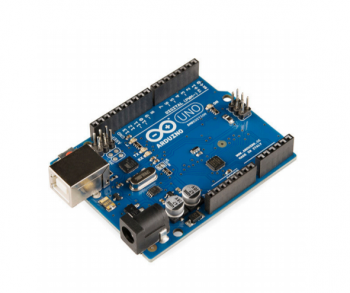
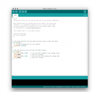
Arduino is composed of two major parts: the Arduino board, which is the piece of hardware you work on when you build your objects; and the Arduino IDE, the piece of software you run on your computer. You use the IDE to create a sketch (a little computer program) that you upload to the Arduino board. The sketch tells the board what to do.
In the meantime, HERE you can find anything about Arduino, including download the software.
In essence Arduino is just another μController development board. The main purpose of such a μController development board is to make it easy for developers to evaluate the functions of, or create a quick prototype with, a certain type of μController. μControllers come in al sorts of tastes and sizes hence there are many different flavours of μController development boards as well. Do, for example, a Google search on microcontroller development board. You will see an abundance of different different platforms and most likely you will find some Arduino flavours there as well.
A bit of Arduino history
The project is based on a family of microcontroller board designs manufactured primarily by SmartProjects in Italy, and also by several other vendors, using various 8-bit Atmel AVR microcontrollers or 32-bit Atmel ARM processors. These systems provide sets of digital and analog I/O pins that can be interfaced to various extension boards and other circuits. The boards feature serial communications interfaces, including USB on some models, for loading programs from personal computers. For programming the microcontrollers, the Arduino platform provides an integrated development environment (IDE) based on the Processing project, which includes support for C and C++ programming languages.
The first Arduino was introduced in 2005. The project leaders sought to provide an inexpensive and easy way for hobbyists, students, and professionals to create devices that interact with their environment using sensors and actuators. Common examples for beginner hobbyists include simple robots, thermostats and motion detectors.
What do you use Arduino for?
Arduino is involved in lots of works. Here are some examples:
- Sound sculptures
- Sensing pollution
- Performance / Microphone manipulation
- Light swarm
- Machines that almost fall over
- Mom, I hit a man
- Forbidden fruit machine
- As light goes by
- Instant messanging?
- String fountain
- What the phonics
- A piece of privacy
- Can be very simple
- Even more simple
- Bottle song test
- Bottle song
- Simple and with a sense of humor 1
- Simple and with a sense of humor 2
- Same but different
The Arduino board
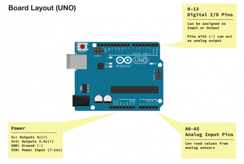
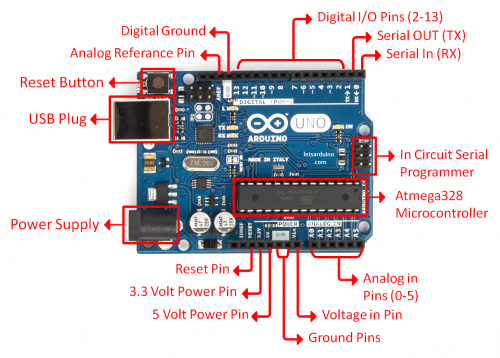
The pins on your Arduino are the places where you connect wires to construct a circuit (probably in conjunction with a breadboard and some wire. They usually have black plastic ‘headers’ that allow you to just plug a wire right into the board. The Arduino has different kinds of pins, each of which is labeled on the board and used for different functions.
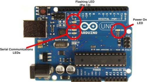
In details:
Inputs and Outputs
μControllers like Arduino are optimized for control of general input and output.
What are those two exactly?
Analog Input Pins ( we have six of them in the Uno): The area of pins under the ‘Analog In’ label (A0 through A5 on the UNO) are Analog In pins. These pins can read the signal from an analog sensor (like a temperature sensor) and convert it into a digital value that we can read.
Digital Input Pins (seven on the Uno): Across from the analog pins are the digital pins (0 through 13 on the UNO). These pins can be used for both digital input (like telling if a button is pushed) and digital output (like powering an LED).
Getting started on the Arduino board and software
Now that we have our board we should start by figuring put if our Arduino is all good or it is somehow damaged. To do this we are running a simple script on the board.
You can download the Arduino software here.
To upload the sketch you can got to:
File ---> Examples ---> Basics --->Blink
You will see something like this:
/*
  Blink
  Turns on an LED on for one second, then off for one second, repeatedly.

  Most Arduinos have an on-board LED you can control. On the Uno and
  Leonardo, it is attached to digital pin 13. If you're unsure what
  pin the on-board LED is connected to on your Arduino model, check
  the documentation at http://www.arduino.cc

  This example code is in the public domain.

  modified 8 May 2014
  by Scott Fitzgerald
 */


// the setup function runs once when you press reset or power the board
void setup() {
  // initialize digital pin 13 as an output.
  pinMode(13, OUTPUT);
}

// the loop function runs over and over again forever
void loop() {
  digitalWrite(13, HIGH);   // turn the LED on (HIGH is the voltage level)
  delay(1000);              // wait for a second
  digitalWrite(13, LOW);    // turn the LED off by making the voltage LOW
  delay(1000);              // wait for a second
}
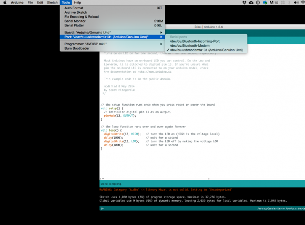
To make sure your board is connected you should check a couple of things
- Make sure your board and port is selected
- Compile the sketch
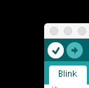
- Press/ Click upper most left button, looks like a Tick. Observe the messages appearing in the bottom of the Arduino software window. There must be a sentence Done Compiling
- Press/ Click upper most left button, looks like a Tick. Observe the messages appearing in the bottom of the Arduino software window. There must be a sentence Done Compiling
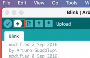
- Upload the sketch on the board
Example: Getting data from an input
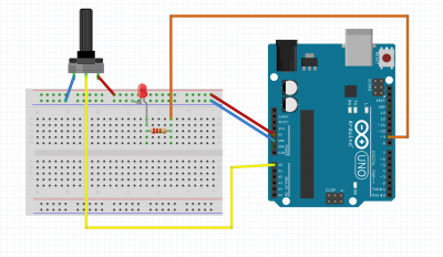
The knob
/*
  AnalogReadSerial

  Reads an analog input on pin 0, prints the result to the Serial Monitor.
  Graphical representation is available using Serial Plotter (Tools > Serial Plotter menu).
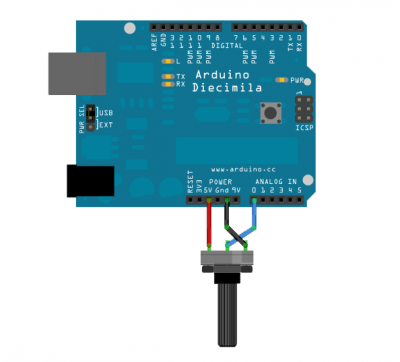
  Attach the center pin of a potentiometer to pin A0, and the outside pins to +5V and ground.

  This example code is in the public domain.

  http://www.arduino.cc/en/Tutorial/AnalogReadSerial
*/

// the setup routine runs once when you press reset:
void setup() {
  // initialize serial communication at 9600 bits per second:
  Serial.begin(9600);
}

// the loop routine runs over and over again forever:
void loop() {
  // read the input on analog pin 0:
  int sensorValue = analogRead(A0);
  // print out the value you read:
  Serial.println(sensorValue);
  delay(1);        // delay in between reads for stability
}
int potPin = A0;
int potValue = 0;
int ledPin = 9;


void setup() {
  // put your setup code here, to run once:

Serial.begin(9600);
}

void loop() {
  // put your main code here, to run repeatedly:
 potValue = analogRead(potPin);
 Serial.println(potValue);
 analogWrite(ledPin, potValue);
}
Now MAP the values
int potPin = A0;
int potValue = 0;
int ledPin = 9;


void setup() {
  // put your setup code here, to run once:

  Serial.begin(9600);
}

void loop() {
  // put your main code here, to run repeatedly:
  potValue = analogRead(potPin);
  int mappedValue = map(potValue, 0, 1023, 0, 255);
  analogWrite(ledPin, mappedValue);
}
Notes
Here you will find a PDF with diagrams from the Arduino Basics Workshop:
Media:arduino_basics_workshop.pdf
