Difference between revisions of "Baremetal Arduino"
m |
|||
| (7 intermediate revisions by the same user not shown) | |||
| Line 1: | Line 1: | ||
| − | {{ | + | {{TOC right}} |
<cite> | <cite> | ||
'''Bare machine''' (or '''bare metal'''), in computer parlance, means a computer without its operating system. Modern operating systems evolved through various stages, from elementary to the present day complex, highly sensitive real-time systems. In the very first stage of computing there was nothing like an operating system at all. Programs were fed to the computer system directly using machine language by the programmers without any system software support. This approach is termed the "bare machine" approach in the development of operating systems. | '''Bare machine''' (or '''bare metal'''), in computer parlance, means a computer without its operating system. Modern operating systems evolved through various stages, from elementary to the present day complex, highly sensitive real-time systems. In the very first stage of computing there was nothing like an operating system at all. Programs were fed to the computer system directly using machine language by the programmers without any system software support. This approach is termed the "bare machine" approach in the development of operating systems. | ||
| Line 6: | Line 6: | ||
Here with Bare metal we mean the μController without it's Arduino layer. We remove the μController from it's comfortable position on the Arduino hardware and place it on a breadboard. This page will take you throught the steps on how to do this. It will not tell you how you should layout your breadboard. These are considered ''implementation details'' and are up to the you. However, to assist with this there is a Fritzing<ref name="fritzing">http://www.fritzing.org</ref> project available with the electrical schematic and starting point for laying out your breadboard design. | Here with Bare metal we mean the μController without it's Arduino layer. We remove the μController from it's comfortable position on the Arduino hardware and place it on a breadboard. This page will take you throught the steps on how to do this. It will not tell you how you should layout your breadboard. These are considered ''implementation details'' and are up to the you. However, to assist with this there is a Fritzing<ref name="fritzing">http://www.fritzing.org</ref> project available with the electrical schematic and starting point for laying out your breadboard design. | ||
| − | |||
| − | |||
| − | |||
| − | |||
The steps we need to follow: | The steps we need to follow: | ||
| − | # download and install Fritzing | + | # download and install Fritzing. |
# download and install the Arduino Unleashed project files | # download and install the Arduino Unleashed project files | ||
# create your breadboard layout using Fritzing | # create your breadboard layout using Fritzing | ||
| Line 18: | Line 14: | ||
# program the μController | # program the μController | ||
| − | == | + | '''Note:''' this page is a work in progress. |
| − | + | ||
| + | == Download and install the Arduino Unleashed project files == | ||
| + | The Arduino Unleashed project files can be found in the [https://github.com/mywdka WdKA Github repository]. If you are familiar with git<ref>http://www.git-scm.com/</ref> you can clone the Arduino Unleashed [https://github.com/mywdka/ArduinoUnleashed repository]. Otherwise download a zipped copy of it [https://github.com/mywdka/ArduinoUnleashed/archive/master.zip here]. | ||
| + | |||
| + | To install the Arduino Unleashed board to your Arduino environment follow the following steps<ref>You will need at least version 1.6.0 of the Arduino IDE</ref>: | ||
| + | * in your Arduino sketch folder<ref>Usually Documents/Arduino for OSX and Windows, ~/Arduino on GNU/Linux</ref> create a folder called <code>hardware</code> | ||
| + | * unpack the zip file and copy the folder WdKA into the hardware folder you just created | ||
| + | * start the Arduino IDE and verify in the boards menu there is a new board called ''Arduino Unleashed Uno'' | ||
| + | |||
| + | That's it :-) | ||
| + | |||
| + | == Create your breadboard layout using Fritzing == | ||
| + | To help you along the way there is a Fritzing<ref name="fritzing"/> project ''BareMetalArduino.fzz'' in the BaremetalArduino directory of the zip archive you downloaded. To get the latest version you can also download it [https://github.com/mywdka/ArduinoUnleashed/raw/master/BaremetalArduino/BareMetalArduino.fzz here]. To open the project you will, of course, need to have Fritzing installed. You can download it for OSX, windows and GNU/Linux at via http://fritzing.org/download . | ||
| + | |||
| + | After you have installed Fritzing start it and open the project ''BareMetalArduino.fzz''. | ||
| + | |||
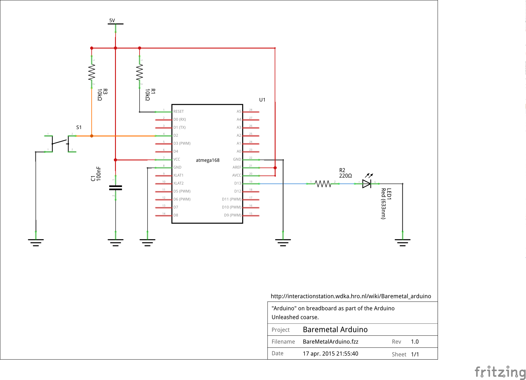
| + | The project contains the '''electric schematic''': | ||
| + | <span class="plainlinks"><div class="image320px">[https://raw.githubusercontent.com/mywdka/ArduinoUnleashed/master/BaremetalArduino/BareMetalArduino_schem.png https://raw.githubusercontent.com/mywdka/ArduinoUnleashed/master/BaremetalArduino/BareMetalArduino_schem.png]</div></span> | ||
| + | And a template to start your '''breadboard layout''': | ||
| + | <span class="plainlinks"><div class="image320px">[https://raw.githubusercontent.com/mywdka/ArduinoUnleashed/master/BaremetalArduino/BareMetalArduino_bb.png https://raw.githubusercontent.com/mywdka/ArduinoUnleashed/master/BaremetalArduino/BareMetalArduino_bb.png]</div></span> | ||
| − | == | + | To make it a bit easier the following rules have been followed: |
| − | + | * all <span style="color: red;">'''red bar'''</span> are connected to the '''+5V''', make sure you also connect the +5v to the row with the <span style="color: red;">'''red wires''' on the breadboard. | |
| − | = | + | * all '''black wires''' are connected to the '''GND''', make sure you also connect the GND to the row with the <span style="color: blue;">'''blue bar''' on the breadboard. |
| − | = | + | * all <span style="color: orange;">'''orange wires'''</span> have a relation to the button |
| + | * all <span style="color: blue;">'''blue wires'''</span> have a relation to the LED | ||
| + | The connections (wires / lines) in the schematic view are represented as dashed lines in the breadboard view. Remember that a '''dot''' on the intersection of two lines crossing each other means they are electrically connected! If there is '''no dot''' there is '''no''' connection. | ||
| + | |||
| + | Now go ahead and play around with Fritzing and create the schematic layout on the breadboard. Try to work as neat as possible with as little wires as possible. This will make it a lot easier to transfer your layout into the real world during the next step. | ||
| + | |||
| + | And don't forget to '''save''' your work '''regularly'''! | ||
| + | |||
| + | == Copy your breadboard layout to the physical world == | ||
| + | == Program the μController == | ||
== Unleash your μController == | == Unleash your μController == | ||
| + | '''One note of warning:''' work carefully, detailed and pay attention to the correct orientation and pin numbering of the parts. Hooking up your power source the wrong way can destroy the μController. | ||
| + | |||
First of all you need to relieve the μController from the Arduino board. Another option is to buy one. The μController on the Arduino is the Atmel AVR ATMEGA328P-PU, you can order these for example at [https://www.conrad.nl/nl/atmel-avr-risc-microcontroller-atmel-atmega328p-pu-soort-behuizing-pdip-28-flash-geheugen-32-kb-geheugen-ram-2-kb-155197.html Conrad]. | First of all you need to relieve the μController from the Arduino board. Another option is to buy one. The μController on the Arduino is the Atmel AVR ATMEGA328P-PU, you can order these for example at [https://www.conrad.nl/nl/atmel-avr-risc-microcontroller-atmel-atmega328p-pu-soort-behuizing-pdip-28-flash-geheugen-32-kb-geheugen-ram-2-kb-155197.html Conrad]. | ||
| Line 34: | Line 60: | ||
| − | |||
== Notes & References == | == Notes & References == | ||
Revision as of 02:28, 20 April 2015
Bare machine (or bare metal), in computer parlance, means a computer without its operating system. Modern operating systems evolved through various stages, from elementary to the present day complex, highly sensitive real-time systems. In the very first stage of computing there was nothing like an operating system at all. Programs were fed to the computer system directly using machine language by the programmers without any system software support. This approach is termed the "bare machine" approach in the development of operating systems. [1]
Here with Bare metal we mean the μController without it's Arduino layer. We remove the μController from it's comfortable position on the Arduino hardware and place it on a breadboard. This page will take you throught the steps on how to do this. It will not tell you how you should layout your breadboard. These are considered implementation details and are up to the you. However, to assist with this there is a Fritzing[2] project available with the electrical schematic and starting point for laying out your breadboard design.
The steps we need to follow:
- download and install Fritzing.
- download and install the Arduino Unleashed project files
- create your breadboard layout using Fritzing
- copy your breadboard layout to the physical world
- program the μController
Note: this page is a work in progress.
Download and install the Arduino Unleashed project files
The Arduino Unleashed project files can be found in the WdKA Github repository. If you are familiar with git[3] you can clone the Arduino Unleashed repository. Otherwise download a zipped copy of it here.
To install the Arduino Unleashed board to your Arduino environment follow the following steps[4]:
- in your Arduino sketch folder[5] create a folder called
hardware - unpack the zip file and copy the folder WdKA into the hardware folder you just created
- start the Arduino IDE and verify in the boards menu there is a new board called Arduino Unleashed Uno
That's it :-)
Create your breadboard layout using Fritzing
To help you along the way there is a Fritzing[2] project BareMetalArduino.fzz in the BaremetalArduino directory of the zip archive you downloaded. To get the latest version you can also download it here. To open the project you will, of course, need to have Fritzing installed. You can download it for OSX, windows and GNU/Linux at via http://fritzing.org/download .
After you have installed Fritzing start it and open the project BareMetalArduino.fzz.
The project contains the electric schematic:
And a template to start your breadboard layout:
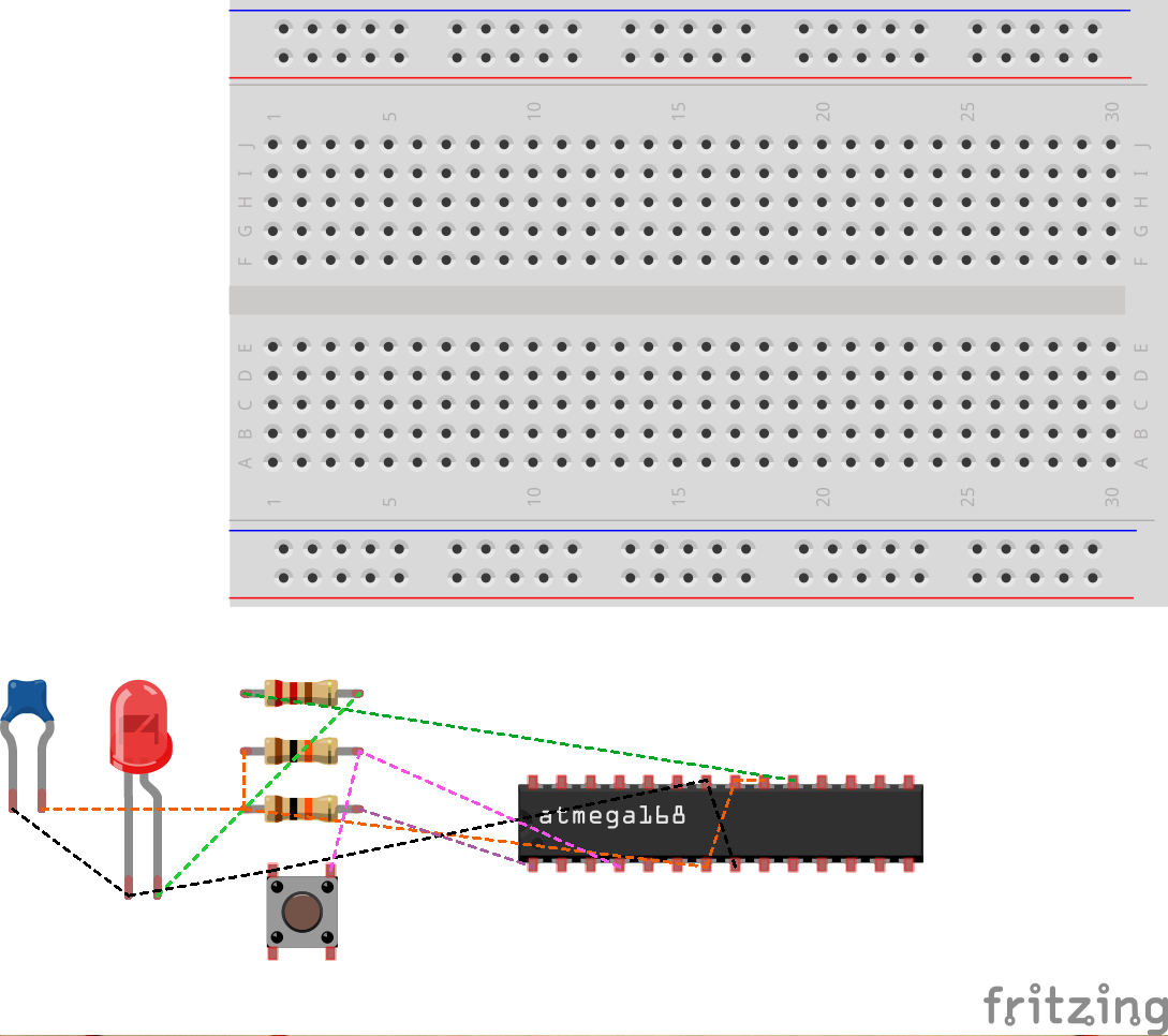
To make it a bit easier the following rules have been followed:
- all red bar are connected to the +5V, make sure you also connect the +5v to the row with the red wires on the breadboard.
- all black wires are connected to the GND, make sure you also connect the GND to the row with the blue bar on the breadboard.
- all orange wires have a relation to the button
- all blue wires have a relation to the LED
The connections (wires / lines) in the schematic view are represented as dashed lines in the breadboard view. Remember that a dot on the intersection of two lines crossing each other means they are electrically connected! If there is no dot there is no connection.
Now go ahead and play around with Fritzing and create the schematic layout on the breadboard. Try to work as neat as possible with as little wires as possible. This will make it a lot easier to transfer your layout into the real world during the next step.
And don't forget to save your work regularly!
Copy your breadboard layout to the physical world
Program the μController
Unleash your μController
One note of warning: work carefully, detailed and pay attention to the correct orientation and pin numbering of the parts. Hooking up your power source the wrong way can destroy the μController.
First of all you need to relieve the μController from the Arduino board. Another option is to buy one. The μController on the Arduino is the Atmel AVR ATMEGA328P-PU, you can order these for example at Conrad.
To remove the chip from your Arduino can be a bit challenging. Carefully push a small flat screwdriver in between the chip and the socket lifting the chip out of its socket bit by bit. Be careful not to bend the legs too much as they will break easily.
Notes & References
- ↑ https://en.wikipedia.org/wiki/Bare_machine
- ↑ 2.0 2.1 http://www.fritzing.org
- ↑ http://www.git-scm.com/
- ↑ You will need at least version 1.6.0 of the Arduino IDE
- ↑ Usually Documents/Arduino for OSX and Windows, ~/Arduino on GNU/Linux