Animation: History, resources, and other good stuff
Pre-cinematic animation devices
History
Animation - as we might understand it as a technical process of synthesising motion from a series of static images - precedes the invention of the cinematograph by several decades. It has its roots in the numerous game toys / devices, popular in the early 1800s which experimented with persistence of vision effect known as the Phi phenomenon.
Thaumatrope
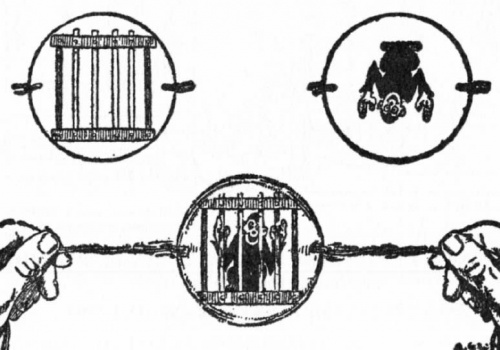
The Thaumatrope accredited to three different people, Dr Fitton of London, Peter Roget and London physicist John Ayrton Paris. However it is known that Paris used his device to show the Phi phenomenon to the Royal College of Physicians in 1824. Its consisted of a disc with an image painted on each side. When the disc was spun by pulling on a twisted pair of strings, the images seemed to be combined - a bird on one side of the disc would appear in the empty cage on the other side. 'Trope' comes from the Greek word for 'things that turn'. 'Thauma' means wondrous, therefore a thaumatrope is a 'turning marvel' or 'wonder turner'.
LINKS - - - - - >
how it works
Phenakistoscope and Stroboscope
In 1832 Joseph Plateau (Ghent, Belgium) coined his invention - the phenakistoscope (Greek for 'deceptive view'). That same year, professor Simon Ritter von Stampfer of the Polytechnical Institute (Vienna, Austria) developed the Stampfer Disc (also called the Stroboskopische Sheiben, Stroboscope Discs, optical magic disc, or simply Stroboscope ). Essentially, this was the same device as Plateau's phenakistoscope. These devices were also known under other names such as: Fantascope, Phantamascope, Magic Disc or Kaleidorama.
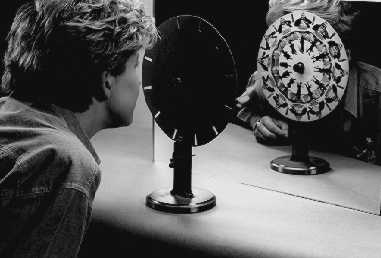
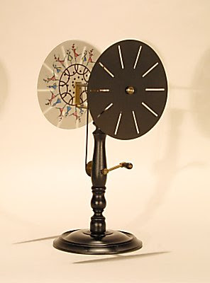
The simplest phenakistoscope is a spinning disc mounted vertically on a handle. Arranged around the circumference of the disc is a series of equidistant radial slots (usually between 8 and 20), and on the face of the disc a series of pictures representing phases of movement of objects, people or animals. The user spins the disc and looks through the moving slots at the sequence reflected in a mirror, the rapid succession of pictures having the appearance of a moving image. The discs were sold in sets, and could be attached and removed from the handle by a simple fixture.
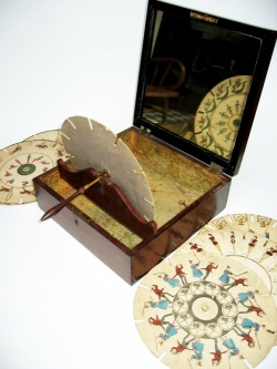
A later version, which eliminated the need for a mirror, had two discs fixed at a distance on the same axis, one with slots and the other (changeable) with pictures. Some sets were designed as table models on wooden stands, with a handle to drive the discs by pulleys.
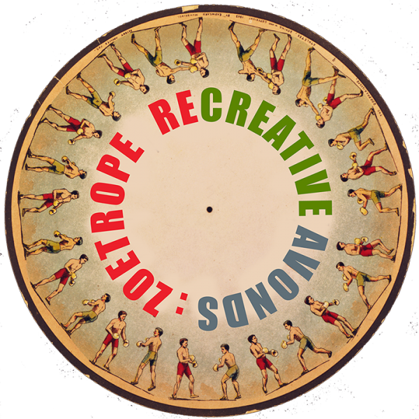
Zoetrope
The Zoetrope was invented by William George Horner in 1834. He named his device Daedalum or 'wheel of the devil'. This optical toy was forgotten for about 30 years until it was discovered and almost simultaneously patented in 1867 by William F. Lincoln, USA and in England by Milton Bradley. It was from Lincoln that the device received its new name Zoetrope, meaning 'wheel of life' from the Greek word 'zoo' for animal life and 'trope' for 'things that turn'.
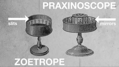
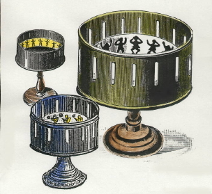
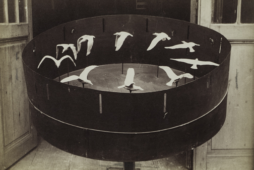
Horner's Zoetrope was an adaptation of the principles of the Phenakistoscope. However it was more convenient than Plateau and Stampfer's inventions in that it eliminated the need for a mirror and allowed several people to view the motion at one time. It was constructed of an open-top drum into which was placed a hand drawn sequence of pictures on a strip of paper facing inwards. The outside of the drum had slits cut into the cylindrical surface. When the drum was spun on a central axis, the images could be viewed through the slits giving rise to the illusion of movement.
a short video, always better than words
Praxinoscope
In 1877, Frenchman Charles Émile Reynaud, refined the principle of the Zoetrope to use reflected light creating the Praxinoscope (patented December 1877). This was the first device to overcome the blurred distortion caused by viewing through narrow fast moving slots and it quickly replaced the Zoetrope in popularity. Like the Zoetrope, a paper strip of pictures is placed inside a shallow outer cylinder, so that each picture is reflected by the inner set of mirrors. The number of mirror facets equaled the number of pictures on the paper strip. When the outer cylinder rotates, the quick succession of images reflected in the mirrors gives the illusion of movement. This produced a image that was more brilliant and sharper than with any previous device.
Reynaud managed to adapt the principle behind his Praxinoscope to project a series of pictures onto a screen. 1892 in Paris, he opened the 'Theatre Optique' - the very first moving pictures shown publicly via projection onto a screen.
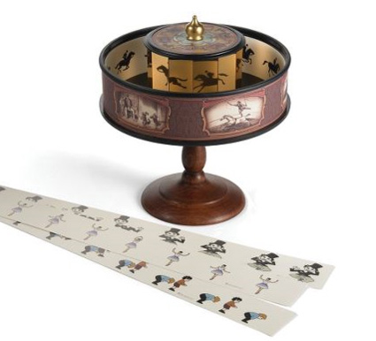
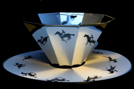
video that shows it:)
and now a useful image to get the difference :)
Technology
In short, in order to experience static images as an animated sequence, they must be viewed in a rapid succession and there must be a break of the viewing of the images. In the case of the early animation devices, the images were seen trough a slit, that revealed the image for a brief moment and then there was a break before seeing the next one. This we can call the shutter.
There are other ways to create the shutter, and allow for the animation to be observed.
We will look into two:
- using a camera's framerate
- using strobe light (light flashing with a high frequency)
There is also the factor of how long the images are exposed to the viewer. That determines the motion blur, or how sharp do we see the image.
That will be the shutter speed at which the camera films in the first case
And will be the fraction of a second at which the light is on in the case of the strobe
Understanding the relationship of these factors- check 2.1 Strobe light + sync
Recent projects
Some very few works that employ the same principles
Tim Wheatley
Tim Wheatley is an animator, thus the projects is only seen trough camera
Gregory Barsamian
quite amazing sculptural, stroboscopic works. His website design is almost as dazzling:)
Julien Maire
a 3d printed film
Scott Blake
9/11 Zoetrope by the artist
Bill Brandt
Msstransiscope - Public space artwork
Troika
digital zoetrope
Quinten Swagerman
Pristitrope
Takeshi Murata
sculptural, stroboscopic optical illusion / with flawless documentation
Peter Hudson
huge scale 3d zoetropes at Burning man - this is the man
Disney's toy story 3d zoetrope
A music video using praxinoscopes
Sculpture describe themselves as an Opto-musical agglomerate
Sculpture set
Interaction Station Zoetrope teststation
During the first Zoetrope Open Aanbod we built two test stations. They are available in the Interaction station to test animations and make prototypes.
Instructions and documentation to follow here------>
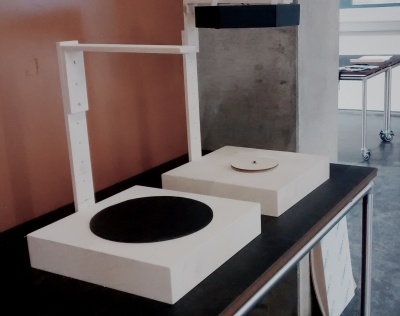
Potentially useful re-creative technology
Strobe Light + Sync
or stroboscopic light very simply put is a light source that lights on and off very fast. Hope none of us suffers from being exposed at strobing light, as you will probably use it for your projects to be your shutter.
So to shortly wrap it up,
persistence of vision is a stroboscopic effect. The images you see must be interrupted by moments of darkness in order for the illusion to work.
That is how the phenakistoscope and zoetrope's slits work. The same is achieved with separate mirrors in the case of the praxinoscope.
So there are three factors that we must take into consideration when building an animation device that works with the same principles.
1. Number of frames of animation 2. Frequency of the strobe or Frames per second (fps) 3. Rotations per second of the device (speed)
With the devices, that have slits to create the stroboscopic effect, there is no problem with synchronization, since the faster you turn the faster the slits move. And since they are the same number as the images and placed always so that you see the opposite image, the animation is always in sync.
But when there is a light source or camera frame rate that creates the gaps in between the frames, then there is a formula to calculate the relationship.
The Rotations per second x number of frames of animation = Frequency of the strobe or camera fps
and then by knowing two of the three factors, you can calculate the other
A good example to understand this is understanding the turntable (record player animation)
So there 2 factors are present
1. the speed of the record player - that is 45 RPM (rotations per minute), which is 45rpm/60=0.75 RPS rotations per second
2. the fps of a camera is 24 fps
so according to the formula
0.75 x frames of animation = 24
or frames of animation = 24/0.75 ----> frames of animation = 32
Another factor that plays a role is the actual raction of the second that the light is on in the case of the strobe, or the shutter speed, when using a camera.
of course, that is a mathematical formula that gives you a very good orientation but it is best to adjust the strobe according to the images, while actually looking at it.
Motors
!!! WATCH THIS / very nice video from the Prelinger Archives, the motor part starts at 06:12
DC motors
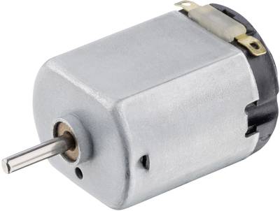
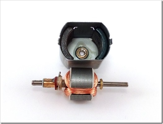
DC (Direct Current) motors are two wire (power & ground), continuous rotation motors. When you supply power, a DC motor will start spinning until that power is removed. Most DC motors run at a high RPM (revolutions per minute).
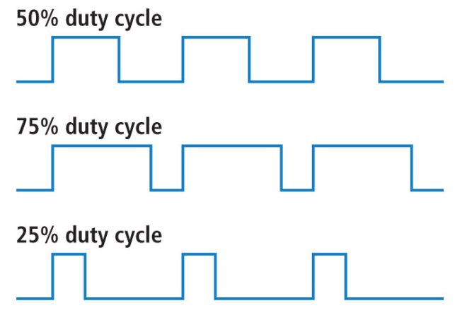
The speed of DC motors is controlled using pulse width modulation (PWM), a technique of rapidly pulsing the power on and off. The percentage of time spent cycling the on/off ratio determines the speed of the motor, e.g. if the power is cycled at 50% (half on, half off), then the motor will spin at half the speed of 100% (fully on). Each pulse is so rapid that the motor appears to be continuously spinning with no stuttering!
PWM examples of duty cycles
servo motors
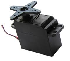
Servo motors are basically more flavored Dc motors.
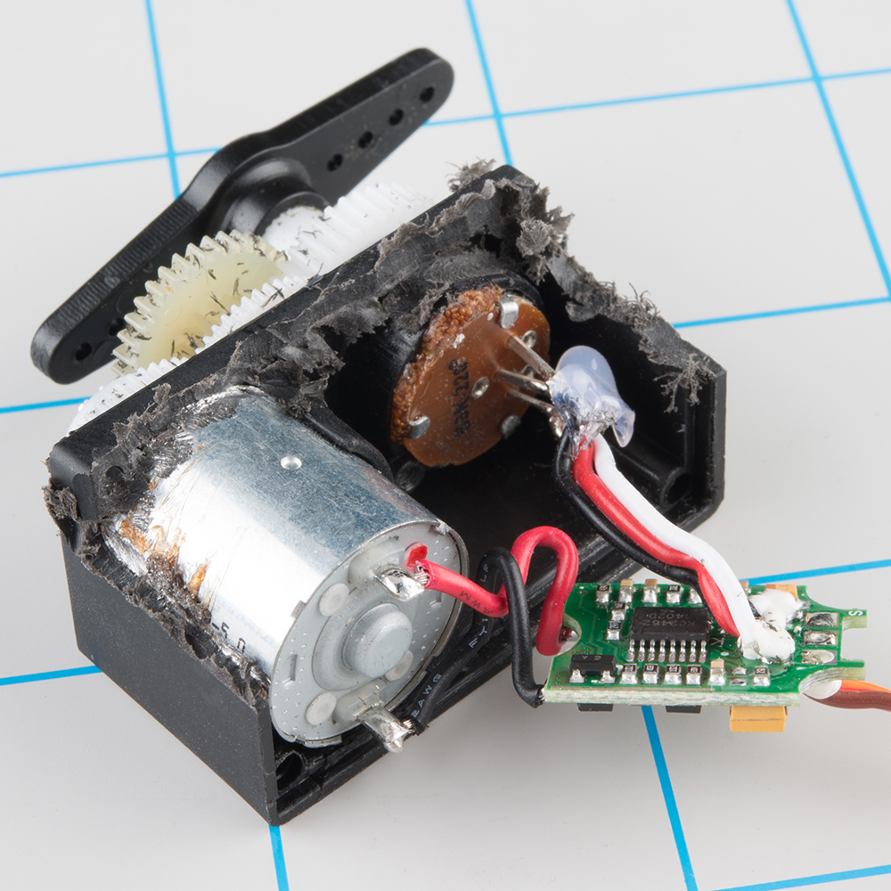
They are generally an assembly of four things: a DC motor, a gearing set, a control circuit and a position-sensor (usually a potentiometer).
The position of servo motors can be controlled more precisely than those of standard DC motors, and they usually have three wires (power, ground & control). Power to servo motors is constantly applied, with the servo control circuit regulating the draw to drive the motor.
Servo motors do not rotate freely like a standard DC motor. Instead the angle of rotation is limited to 180 Degrees back and forth. Servo motors receive a control signal that represents an output position and applies power to the DC motor until the shaft turns to the correct position, determined by the position sensor.
PWM is used for the control signal of servo motors. However, unlike DC motors it’s the duration of the positive pulse that determines the position, rather than speed, of the servo shaft. A neutral pulse value depending on the servo (usually around 1.5ms) keeps the servo shaft in the center position. Increasing that pulse value will make the servo turn clockwise, and a shorter pulse will turn the shaft anticlockwise. The servo control pulse is usually repeated every 20 milliseconds, essentially telling the servo where to go, even if that means remaining in the same position.
stepper motors
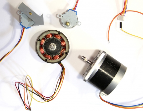
A stepper motor is essentially a servo motor that uses a different method of motorization. Where a servo motor uses a continuous rotation DC motor and integrated controller circuit, stepper motors use multiple toothed electromagnets arranged around a central gear to define position.
Stepper motors require an external control circuit or micro controller (for instance a Raspberry Pi or Arduino) to individually energize each electromagnet and make the motor shaft turn. When electromagnet ‘A’ is powered it attracts the gear’s teeth and aligns them, slightly offset from the next electromagnet ‘B’. When ‘A’ is switch off, and ‘B’ switched on, the gear rotates slightly to align with ‘B’, and so on around the circle, with each electromagnet around the gear energizing and de-energizing in turn to create rotation. Each rotation from one electromagnet to the next is called a "step", and thus the motor can be turned by precise predefined step angles through a full 360 Degree rotation.
Stepper motors are available in two varieties; unipolar or bipolar. Bipolar motors are the strongest type of stepper motor and usually have four or eight leads. They have two sets of electromagnetic coils internally, and stepping is achieved by changing the direction of current within those coils. Unipolar motors, identifiable by having 5,6 or even 8 wires, also have two coils, but each one has a center tap. Unipolar motors can step without having to reverse the direction of current in the coils, making the electronics simpler. However, because the center tap is used to energize only half of each coil at a time they typically have less torque than bipolar.
The design of the stepper motor provides a constant holding torque without the need for the motor to be powered and, provided that the motor is used within its limits, positioning errors don't occur, since stepper motors have physically predefined stations.
Resources
RPM
stepper motors, controlled via a micro controller are easy to follow at what rpm they operate, and to be adjusted e with dc motors, it is a fixed rpm with a small torque, at which the motor operates, and in order to adjust this, gear systems, pulleys .....there is more
Making things move is a book, very useful, please download it and look especially into Forces, Friction, and Torque (Oh My!) starting page 73 and then The Guts: Bearings, Couplers, Gears, Screws, and Springs page 189 till the end But also check out the website for useful bits and pieces
3d printing
lasercutting
Buying electronics
Here are some online options for getting electronics
diy enthusiasts, a bit pricey but very fast delivery, two dutch websites
- [floris]
here find almost anything
- [farnell]
- [RS]
- and conrad [[1]]
Workshop documentation
...end
