Late Night Soldering : Water
instead of Intro
poetry and electricity, play and conductivity
Before we go any further, I think it’s worth it to spend a bit of time watching a video . Since we use electricity as means to make work, its nice to have some understanding it. There are thousands of videos online, but this one is a pearl from 1945...........really different from any tutorial on youtube, see for yourself
WATCH ME
+some more great videos in case you can't get enough
1
2
Electricity seems to be both familiar and yet abstract. Its quite hard to imagine.
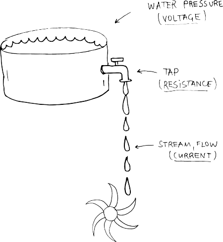
In order imagine electricity, an analogy with water is often used.
Electricity is an essential ingredient of matter. Now ain't that poetic? So to picture it, lets zoom deep in and look at the smallest component of every element - 
Atoms are made of even smaller particles called protons, neutrons, and electrons. The protons and neutrons are packed tightly together in the middle of the atom, and we call them the nucleus of the atom. The electrons orbit around the nucleus. Protons and electrons have electrical charges. Protons have a positive charge, and electrons have a negative charge (neutrons don't have any charge). Normally an atom has equal numbers of protons and electrons, so they cancel each other and the atom has no electrical charge.
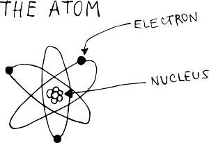
Sometimes an electron escapes from its atom and runs off to join another atom.
Atoms with escaped electrons is positively charged and respectively, if electrons jump into atoms and become more, then the atom is negatively charged.
Free atoms can move freely (almost with the speed of light) trough metals, gases and vacuum. Or they can rest.
The surface that electrons are resting is said to have negative static electrical charge. If atoms are missing some electrons then it is said to be positive static electrical charge.
Current, Voltage, Power, Resistance
So anytime electrons move, we have current! Electrons can travel trough some materials but not trough others. The ones that allow electrons to flow are called Conductors (silver, gold, iron, copper..etc.) and the ones that do not really allow the free flow of electrons are called Insulators ( wood, plastic, rubber..etc.)
Electrical current can flow in either of two directions in a conductor. If it flows only in one direction, then it is called DC ( Directional Current). We will work with it and so the following information concerns DC.
CURRENT (I) - is the quantity of electrons passing at a given point. The unit is the AMPERE, shortly called AMP. If we compare it with water, think of it as the flow of water, the stream coming from the tap.
VOLTAGE (V or E) - is electrical pressure or force. If we now compare it with water, then Voltage is the water pressure.
The higher the pressure, the higher the flow and vice versa.
RESISTANCE (R) - is the conductor's (material’s) tendency to resist the current. Some materials allow more current to flow and others not. Going back to water, resistance is how much the tap is open. It is measured in OHMS (Ω).
OHM's LAW
Mr. Georg Simon Ohm, a German physicist and mathematician, discovered, that there is an interrelation between Voltage, Current and Resistance.
Thus given any two of them, one can find the third one.
V = IxR
I = V/R
R= V/I
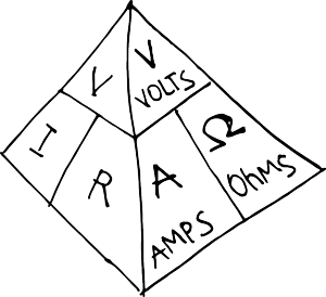
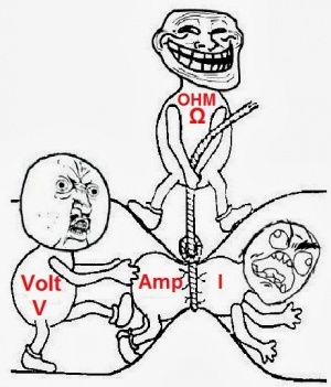
Here is a pyramid that shows it visually.
And shows also the actuial relationship between volts, amps and ohms, which you will see way more often than V, I and R
And here another way we can see it:)
so what is a light object?
It is exactly what the name suggests, BUT in this case the idea of the workshop is to go beyond the mere aesthetic pleasure one is awarded by a blinking led.
We will use a very simple quality of water and conductivity and also a simple circuit to get started working with electronics.
After getting to know what and how the circuits work, one has to work on designing their own object, so that the way it is shaped will determine the message of light.
So after the first week, we will already talk about ideas of what you will be working on.
Is it going to be message on public space, that is revealed with the rain.
Perhaps it is not rain that activates it, other liquids also can be triggers. Test, experiment with what comes to your mind!
I can think of many things that can be challenging, poetic, shocking. Water, wine, blood, sweat, tears, spit.....i guess you already think of more.
Try to design an object that tackles topics, spaces that you dwell in your practice as an artist/designer.
context
Graffiti Reserach Lab and the throwies and post-circuit board
LED Throwies are an inexpensive way to add color to any ferromagnetic surface in your neighborhood.
A Throwie consists of a lithium battery, a 10mm diffused LED and a rare-earth magnet taped together.
Throw it up high and in quantity to impress your friends and city officials.
Post-Circuit Board: enter the age of circuits painted on walls and postage.
Neither snow nor rain nor heat nor law nor gloom of night stays these couriers from the swift completion of their self-appointed rounds.
Lets all Go Postal.
BLINK LINK
Peter Vogel and Alain le Boucher's sculptures
Peter Vogel's work is a result of his interests in dance and the body, composition, in psychology and neurobiology, physics and engineering, combined with a virtuosic craftsmanship in electronic circuit design.
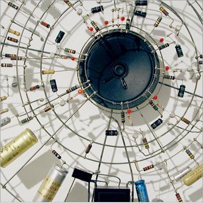
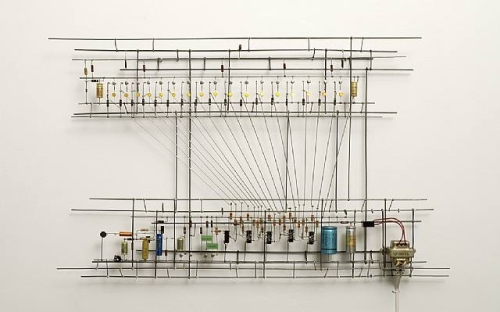
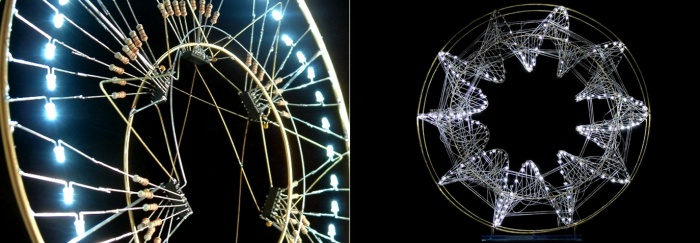
The light in Alain Le Boucher’s sculptures change depending on their programming, which he arranges like music. Through a transparent construction of fine metallic string, the movement and rhythm of light constantly transform the volume and give life to the sculpture.
Tatsuo Miyaijma
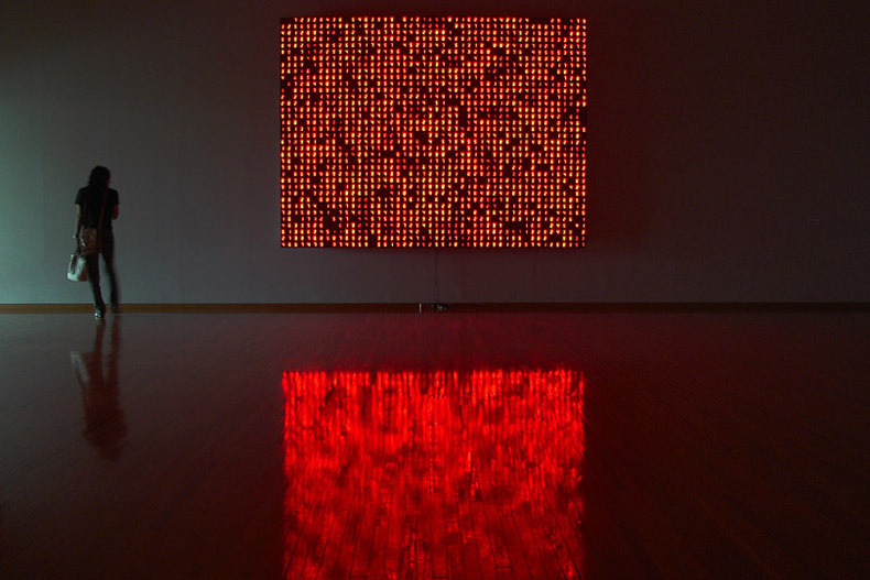
Time and our perception of time as expressed through an ongoing succession of numbers lie at the heart of Tatsuo Miyajima's practice.
His sculptural work consists of networks of colored digital LED devices and integrated circuits.
Humans since 1982
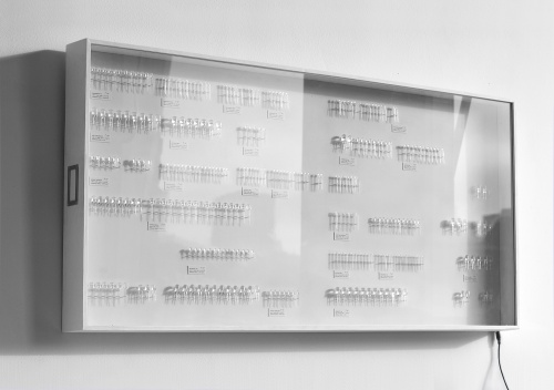
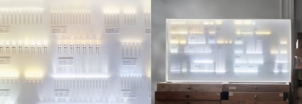
‘Collection of Light’ is simply a collection of LEDs which together constitute a lamp in itself.
The aim is to create an aura of a real collection (similar to a collection of insects) and expose each illuminant as a worthy industrial product.
The LEDs are all labeled (with name, size and colour temperature) and arranged in a specific order to accomplish harmonic light.
getting started
useful
- AC electricity is dangerous, thus do not start experimenting with it.
- Soldering is fun! But the iron is very hot. something that gets melted easily is its own cable, so please mind this:)
- Drink and solder = Bad idea
more will add in the course of our work
tools + materials
We will use
- sodering iron
- multimeter
- pliers both cutter and flat
- leds
- wire
- copper foil
- solder
- desoldering thingy
- pcb
- breadboard
- jumper wires
- etchant (Ferric Chloride)
water, electricity, forward voltage
In any 'loop' of a circuit, the voltages must balance: the amount generated = the amount used
This "Voltage Loop" law was discovered by a fellow named Kirchhoff (dus, it is called Kirchhoff's Voltage Law = KVL). In a loop, where one part is made of the +9V battery. The other half must use up the +9v (making it -9V so that both halves of the loop equal out).
So what does this have to do with the Forward Voltage of an LED? Well, the Forward Voltage is the 'negative voltage', used by the LED when it's on.
Whenever the LED is on, the voltage it uses it up is somewhere between 1.85V and 2.5V. We'll say 2.2V for average - that's a good assumption for most red, yellow, orange and light-green LEDs. If we subtract that from 9V we get about 6.8V left. This is the voltage that must be 'absorbed' by the resistor.
Let's say we have the same circuit above, except this time its a 5V battery and an LED with a forward voltage of 2.5V, how much voltage must be 'absorbed' by the resistor?
Voltages Generate = Voltages used, so 5V = 2.5V + ResistorVoltage. The voltage across the resistor is 2.5V.
Let's say we have a 5V battery and an LED with a forward voltage of 3.4V, how much voltage must be 'absorbed' by the resistor?
Voltages Generate = Voltages used, so 5V = 3.4V + ResistorVoltage. The voltage across the resistor is 1.6V.
Ohm's Law in action
What is interesting about the law we just learned (KVL) is that in no place do we use the resistance of the resistor. It never shows up in the equation. Yet from our previous experiments we know for a fact that changing the resistance affects how bright the LED is.
Next we're going to look into another important law. Let's go back to Ohm's Law- it describes how resistors work.
Voltage across a resistor (volts) = Current through the resistor (amperes)* The Resistance of the resistor (ohms)
Like we said:
V = I * R
If I have a 3 ohm resistor (R) with a current of 0.5 Amperes (I) going through it. What is the voltage (V) across the resistor?
We'll use the V = I * R form of Ohm's Law. V = 0.5 A * 3 ohm = 1.5 Volts.
Now I have a 1000 ohm resistor (R), and a voltage across it of 6.8V (V), what is the current (I) going through the resistor?
We will use the I = V / R form of Ohm's Law. Current = 6.8 V / 1000 = 6.8 milliAmps.
Ohm's law is very important and its becoming familiar with it. I suggest coming up with other mix+match numbers of resistances, currents and voltages and using them to solve for the unknown value. There are also 'calculators' online you can check yourself against.
Solving for the current
We'll now combine both KVL and Ohm's Law. Our LED is connected to a 1000 ohm resistor, and the voltage across that resistor is 6.8V (the law of KVL) so the current through that resistor must be 6.8V / 1000ohm = 6.8 mA (Ohm's law).
The resistor current is 6.8mA and that current is also going through the LED, so the LED current is 6.8mA. "What do I care about the LED current?" The reason you should care is that:
The amount of current (I) going through an LED is directly proportional to how bright it appears.
Series and Parallel Circuits
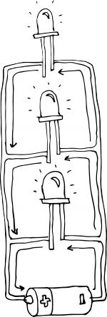
Resistors in series
A series circuit is a circuit in which resistors are arranged in a chain, so the current has only one path to take. The current is the same through each resistor. The total resistance of the circuit is found by simply adding up the resistance values of the individual resistors:
equivalent resistance of resistors in series : R = R1 + R2 + R3 + ...
The current flows through each resistor in turn. If the values of the three resistors are:
R1=8 ohm, R2=8 ohm R3 = 4 ohm
In total resistance is R1 + R2 + R3 = 8+8+4 = 20 Ohm
With a 10 V battery, by V = I R the total current in the circuit is:
I = V / R = 10 / 20 = 0.5 A. The current through each resistor would be 0.5 A.
OK, lets make a simple circuit. Let's wire 2 leds in series. 2 leds with 2.6 V and .02 A each and a power source 9V battery.
In order to calculate we will use Ohm's law
We need to add the led voltages together 2x2.6=5.2V
and so -->
R = (9V - 5.2V) / .02A
R = 190 Ohms so we need to add a 190 Ohms resistor to the circuit
Resistors in Parallel
A parallel circuit is a circuit in which the resistors are arranged with their heads connected together, and their tails connected together. The current in a parallel circuit breaks up, with some flowing along each parallel branch and re-combining when the branches meet again. The voltage across each resistor in parallel is the same.
The total resistance of a set of resistors in parallel is found by adding up the reciprocals of the resistance values, and then taking the reciprocal of the total:
equivalent resistance of resistors in parallel: 1 / R = 1 / R1 + 1 / R2 + 1 / R3 +...
In this case the current supplied by the battery splits up, and the amount going through each resistor depends on the resistance. If the values of the three resistors are:
R1=8 ohm, R2=8 ohm R3 = 4 ohm
The total resistance is found by 1 / R = 1 / 8 + 1 / 8 + 1 / 4 = 1/2 Meaning R = 2 ohms
With a 10 V battery, by V = I R the total current in the circuit is: I = V / R = 10 / 2 = 5 A.
The individual currents can also be found using I = V / R. The voltage across each resistor is 10 V, so:
I1 = 10 / 8 = 1.25 A I2 = 10 / 8 = 1.25 A I3=10 / 4 = 2.5 A
Note that the currents add together to 5A, the total current.
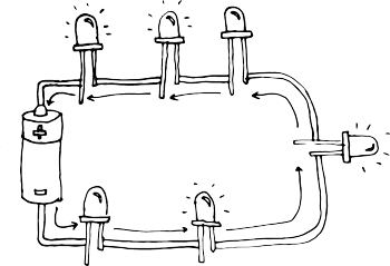
And so, If you wire a whole bunch of LEDs in parallel rather than dividing the power supplied to them between them, they all share it. So, a 12V battery wired to four 3V LEDs in series would distribute 3V to each of the LEDs. But that same 12V battery wired to four 3V LEDs in parallel would deliver the full 12V to each LED - enough to burn out the LEDs for sure!
As an example, lets wire 2 leds 2.6 V each and .02 A in parallel with a 9V power supply.
V=IxR
where:
V1 = supply voltage
V2 = LED voltage
I = LED current (we had been using 20 mA in our other calculations but since wiring LEDs in parallel draws more current I had to multiply the current that one LED draws by the total number of LEDs I was using. 20 mA x 2 = 40 mA, or .04A.
R = (V1 - V2) / I
R= (9V - 2.6V) / .04 A
R = 160 Ohms
So we will use a 160 Ohm resistor for each led
Resources, tutorials and all kinds of useful online places
tools
LED calculator for series and parallel arrays
Ohm's law calculator
Kirchhoff's voltage law
projects, references
jie qi's paper electronics projects
