Making a Schematic in Eagle
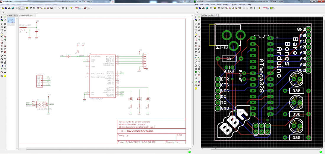
PCB design in EAGLE ( and not only) is a two-step process. First you design your schematic, then you lay out a PCB based on that schematic. EAGLE's board and schematic editors work hand-in-hand. A well-designed schematic is critical to the overall PCB design process. It will help you catch errors before the board is fabricated, and it'll help you debug a board when something doesn't work.
Understanding schematics
Before we begin, you have to make sure you have a good idea about schematics, how to read those. So here is a tutorial
Creating a schematic
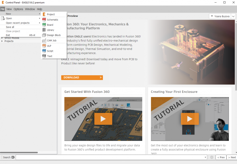
The new Eagle interface opens up with a control panel looking a bit like this

