Making a Schematic in Eagle
Jump to navigation
Jump to search
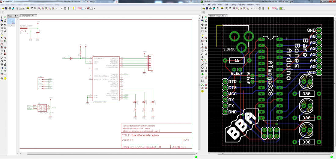
PCB design in EAGLE ( and not only) is a two-step process. First you design your schematic, then you lay out a PCB based on that schematic. EAGLE's board and schematic editors work hand-in-hand. A well-designed schematic is critical to the overall PCB design process. It will help you catch errors before the board is fabricated, and it'll help you debug a board when something doesn't work.
Understanding schematics
Before we begin, you have to make sure you have a good idea about schematics, how to read those. So here is a tutorial
Creating a schematic
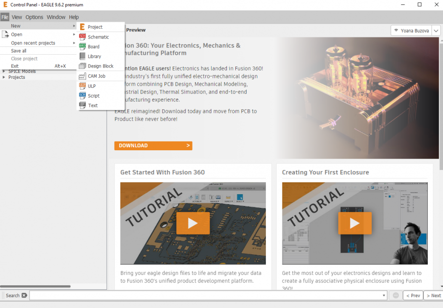
The new Eagle interface opens up with a control panel looking a bit like this
- First, open Autodesk EAGLE, and you’ll be greeted with the Control Panel. This is your home away from home and will contain all of your libraries, projects, scripts, and more.
Under Options >> Directories you will be able to select where your projects, libraries, etc. are managed
- From the Control Panel, select File » New » Project and give your new project folder a name.
- Next, right-click on your project folder and select New » Schematic to add a new schematic sheet to your project.
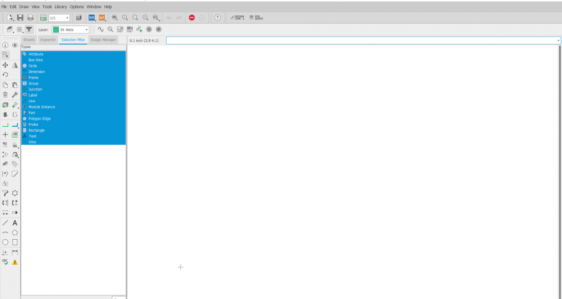
- This will open a blank schematic document. Before you do anything else, save your schematic by selecting File » Save As and give it a name.


