Sensors: Introduction and Types
Analog and Digital sensors
Digital Sensors
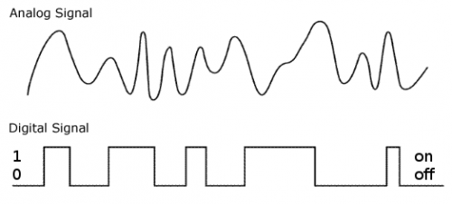
Digital sensors are the sensors that gives 2 state (on/off, 5V/0V). You will connect them to digital Pins and set it as INPUT.
Digital data consists exclusively of 0s and 1s .
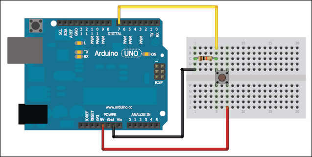
For example, consider a push button switch. This is one of the simplest forms of sensors. It has two discrete values. It is on, or it is off. Other 'discrete' sensors might provide you with a binary value.
Another example of a digital sensor is an accelerometer, which sends a series of data points (speed, direction, and so on) to the Arduino. Usually digital sensors need a chip in the sensor to interpret the physical data.
Analog Sensors
Analog sensors on the other hand, gives range. You connect this types of Analog sensors to Analog Input pins which is measuring the incoming voltage between 0V-5V*. Arduino converts this incoming voltage into the number between 0-1023.
Analog data is transmitted as a continuous signal, almost like a wave. In other words, an analog sensor doesn’t send a burst of 1s and 0s like digital sensors do; instead, the sensor modulates a continuous signal to transmit data.
Microcontrollers are capable of detecting binary signals: is the button pressed or not? These are digital signals. When a microcontroller is powered from five volts, it understands zero volts (0V) as a binary 0 and a five volts (5V) as a binary 1. The world however is not so simple and likes to use shades of gray. What if the signal is 2.72V? Is that a zero or a one? We often need to measure signals that vary; these are called analog signals. A 5V analog sensor may output 0.01V or 4.99V or anything inbetween. Luckily, nearly all microcontrollers have a device built into them that allows us to convert these voltages into values that we can use in a program to make a decision.
An Analog to Digital Converter (ADC) is a very useful feature that converts an analog voltage on a pin to a digital number. By converting from the analog world to the digital world, we can begin to use electronics to interface to the analog world around us.
Not every pin on a microcontroller has the ability to do analog to digital conversions. On the Arduino board, these pins have an ‘A’ in front of their label (A0 through A5) to indicate these pins can read analog voltages.
ADCs can vary greatly between microcontroller. The ADC on the Arduino is a 10-bit ADC meaning it has the ability to detect 1,024 (210) discrete analog levels. Some microcontrollers have 8-bit ADCs (28 = 256 discrete levels) and some have 16-bit ADCs (216 = 65,536 discrete levels).
Analog sensors
The knob or potentiometer
/*
  AnalogReadSerial

  Reads an analog input on pin 0, prints the result to the Serial Monitor.
  Graphical representation is available using Serial Plotter (Tools > Serial Plotter menu).
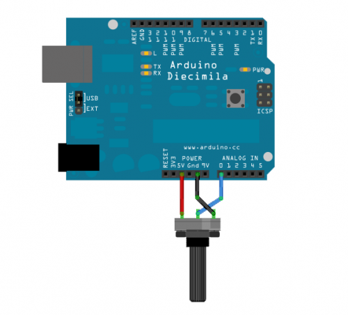
  Attach the center pin of a potentiometer to pin A0, and the outside pins to +5V and ground.

  This example code is in the public domain.

  http://www.arduino.cc/en/Tutorial/AnalogReadSerial
*/

// the setup routine runs once when you press reset:
void setup() {
  // initialize serial communication at 9600 bits per second:
  Serial.begin(9600);
}

// the loop routine runs over and over again forever:
void loop() {
  // read the input on analog pin 0:
  int sensorValue = analogRead(A0);
  // print out the value you read:
  Serial.println(sensorValue);
  delay(1);        // delay in between reads for stability
}
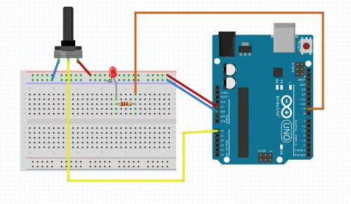
int potPin = A0;
int potValue = 0;
int ledPin = 9;


void setup() {
  // put your setup code here, to run once:

Serial.begin(9600);
}

void loop() {
  // put your main code here, to run repeatedly:
 potValue = analogRead(potPin);
 Serial.println(potValue);
 analogWrite(ledPin, potValue);
}
Now MAP the values
int potPin = A0;
int potValue = 0;
int ledPin = 9;


void setup() {
  // put your setup code here, to run once:

  Serial.begin(9600);
}

void loop() {
  // put your main code here, to run repeatedly:
  potValue = analogRead(potPin);
  int mappedValue = map(potValue, 0, 1023, 0, 255);
  analogWrite(ledPin, mappedValue);
}
LDR: Light Intensity Sensor
The light intensity sensor is very similar to the moisture sensor, only it changes its resistance according to the amount of light that falls onto the LDR.
We basically are doing this, but instead on the breadboard we have it wired to a connector.
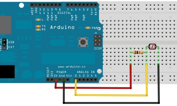
It is an analog sensor and we will connect the YELLOW wire to pin A0 of the Arduino uno.
The BLACK goes to GND
and the RED goest to 5V
Piezo Element
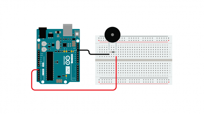
A piezo is an electronic device that generates a voltage when it's physically deformed by a vibration, sound wave, or mechanical strain. Similarly, when you put a voltage across a piezo, it vibrates and creates a tone. Piezos can be used both to play tones and to detect tones.
The sketch reads the piezo output using the analogRead() command, encoding the voltage range from 0 to 5 volts to a numerical range from 0 to 1023 in a process referred to as analog-to-digital conversion, or ADC.
/*
  Knock Sensor

  This sketch reads a piezo element to detect a knocking sound.
  It reads an analog pin and compares the result to a set threshold.
  If the result is greater than the threshold, it writes "knock" to the serial
  port, and toggles the LED on pin 13.

  The circuit:
	- positive connection of the piezo attached to analog in 0
	- negative connection of the piezo attached to ground
	- 1 megohm resistor attached from analog in 0 to ground

  created 25 Mar 2007
  by David Cuartielles <http://www.0j0.org>
  modified 30 Aug 2011
  by Tom Igoe

  This example code is in the public domain.

  https://www.arduino.cc/en/Tutorial/BuiltInExamples/Knock
*/


// these constants won't change:
const int ledPin = 13;       // LED connected to digital pin 13
const int knockSensor = A0;  // the piezo is connected to analog pin 0
const int threshold = 100;   // threshold value to decide when the detected sound is a knock or not


// these variables will change:
int sensorReading = 0;  // variable to store the value read from the sensor pin
int ledState = LOW;     // variable used to store the last LED status, to toggle the light

void setup() {
  pinMode(ledPin, OUTPUT);  // declare the ledPin as as OUTPUT
  Serial.begin(9600);       // use the serial port
}

void loop() {
  // read the sensor and store it in the variable sensorReading:
  sensorReading = analogRead(knockSensor);

  // if the sensor reading is greater than the threshold:
  if (sensorReading >= threshold) {
    // toggle the status of the ledPin:
    ledState = !ledState;
    // update the LED pin itself:
    digitalWrite(ledPin, ledState);
    // send the string "Knock!" back to the computer, followed by newline
    Serial.println("Knock!");
  }
  delay(100);  // delay to avoid overloading the serial port buffer
}
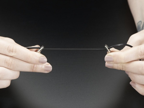
Stretch sensor
Read more about it here.
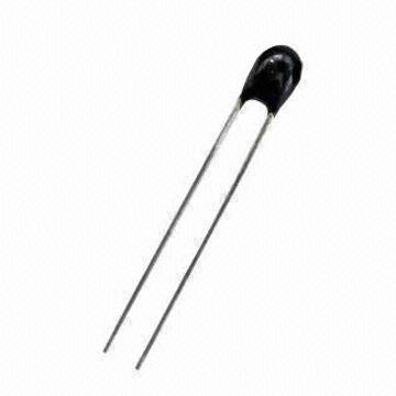
Thermistor
NTC temperature
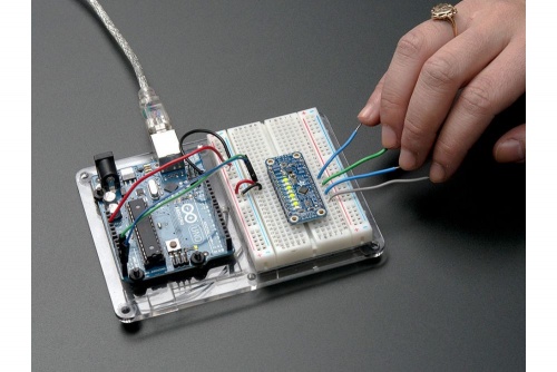
Capacitive Sensor-Analog
adafruit-cap1188-breakout
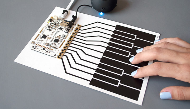
Or touch-board:
Digital sensors
Digital sensors are the sensors that give 2 state (on/off, 5V/0V). You connect them to digital Pins and set them as INPUT.
Digital data consists exclusively of 0s and 1s .
For example, consider a push button switch. This is one of the simplest forms of sensors. It has two discrete values. It is on, or it is off. Other 'discrete' sensors might provide you with a binary value.
Another example of a digital sensor is an accelerometer, which sends a series of data points (speed, direction, and so on) to the Arduino. Usually digital sensors need a chip in the sensor to interpret the physical data.
Button
// constants won't change. They're used here to set pin numbers:
const int buttonPin = 7;     // the number of the pushbutton pin
const int ledPin =  13;      // the number of the LED pin

// variables will change:
int buttonState = 0;         // variable for reading the pushbutton status

void setup() {
  // initialize the LED pin as an output:
  pinMode(ledPin, OUTPUT);
  // initialize the pushbutton pin as an input:
  pinMode(buttonPin, INPUT);
}

void loop() {
  // read the state of the pushbutton value:
  buttonState = digitalRead(buttonPin);

  // check if the pushbutton is pressed. If it is, the buttonState is HIGH:
  if (buttonState == HIGH) {
    // turn LED on:
    digitalWrite(ledPin, HIGH);
  } else {
    // turn LED off:
    digitalWrite(ledPin, LOW);
  }
}
Capacitive sensor
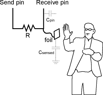
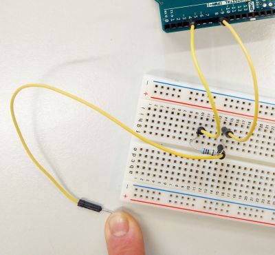
A capacitive sensor, or touch sensor can detect the presence or absence of virtually any object regardless of material. They are are also called touch sensors. There are many touch sensors already made but it is also possible to build your own.
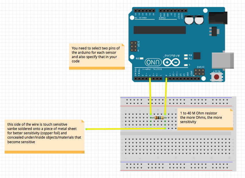
Making a simple capacitive sensor is easy with Arduino, even without the use of any external breakouts.
Using the Capacitive Sensor library https://playground.arduino.cc/Main/CapacitiveSensor?from=Main.CapSense we can make a cap sensor using two arduino pins.
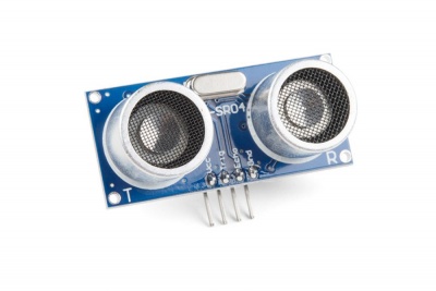
Ultrasonic distance sensor
Ultrasonic Sensor - HC-SR04
#define echoPin 9 // attach pin D9 Arduino to pin Echo of HC-SR04
#define trigPin 10 //attach pin D10 Arduino to pin Trig of HC-SR04

// defines variables
long duration; // variable for the duration of sound wave travel
int distance; // variable for the distance measurement


void setup() {
  pinMode(trigPin, OUTPUT); // Sets the trigPin as an OUTPUT
  pinMode(echoPin, INPUT); // Sets the echoPin as an INPUT
  Serial.begin(9600); // // Serial Communication is starting with 9600 of baudrate speed
  Serial.println("Ultrasonic Sensor HC-SR04 Test"); // print some text in Serial Monitor
  Serial.println("with Arduino UNO R3");
}
void loop() {
  // Clears the trigPin condition
  digitalWrite(trigPin, LOW);
  delayMicroseconds(2);
  // Sets the trigPin HIGH (ACTIVE) for 10 microseconds
  digitalWrite(trigPin, HIGH);
  delayMicroseconds(10);
  digitalWrite(trigPin, LOW);
  // Reads the time the echoPin is high, returns the sound wave travel time in microseconds
  duration = pulseIn(echoPin, HIGH);
  // Calculating the distance
  distance = duration * 0.034 / 2; // Speed of sound wave divided by 2 (go and back)
  // Displays the distance on the Serial Monitor
  Serial.print("Distance: ");
  Serial.print(distance);
  Serial.println(" cm");

}
Infrared sensors
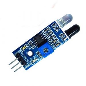
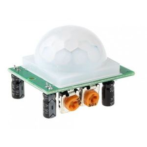
Infrared sensors are able to detect human and animal motion. There are two different types: IR - active infrared sensors (left picture) and PIR -passive infrared sensors (right picture). You can read about the difference here.
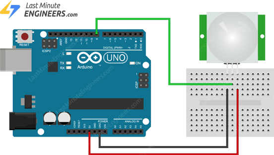
Here is the hook up scheme of the PIR sensor and some example code for Arduino. The code detects whether motion is detected by the sensor. The sensor is able to detect in a range of 3 – 7 meters with an angle of 120 degrees (typically).
int ledPin = 13;                // choose the pin for the LED
int inputPin = 8;               // choose the input pin (for PIR sensor)
int pirState = LOW;             // we start, assuming no motion detected
int val = 0;                    // variable for reading the pin status

void setup() {
  pinMode(ledPin, OUTPUT);      // declare LED as output
  pinMode(inputPin, INPUT);     // declare sensor as input

  Serial.begin(9600);
}

void loop(){
  val = digitalRead(inputPin);  // read input value

  if (val == HIGH)	// check if the input is HIGH
  {
    digitalWrite(ledPin, HIGH);  // turn LED ON

    if (pirState == LOW)
	{
      Serial.println("Motion detected!");	// print on output change
      pirState = HIGH;
    }
  }
  else
  {
    digitalWrite(ledPin, LOW); // turn LED OFF

    if (pirState == HIGH)
	{
      Serial.println("Motion ended!");	// print on output change
      pirState = LOW;
    }
  }
}
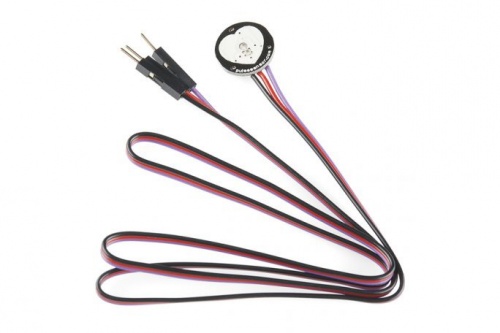
Pulse sensor(heart rate)
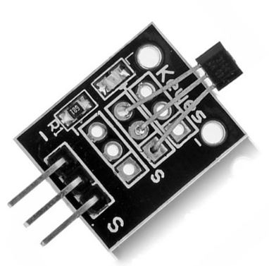
Hall sensor
Soil Moisture sensor
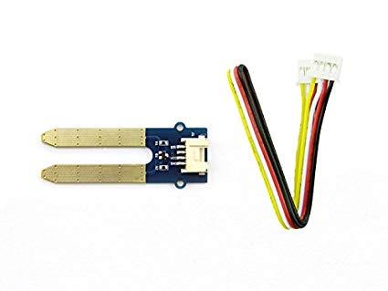
This Moisture Senor can be used for detecting the moisture of soil or judge if there is water around the sensor. It is a soil moisture sensor based on soil resistance measurement.
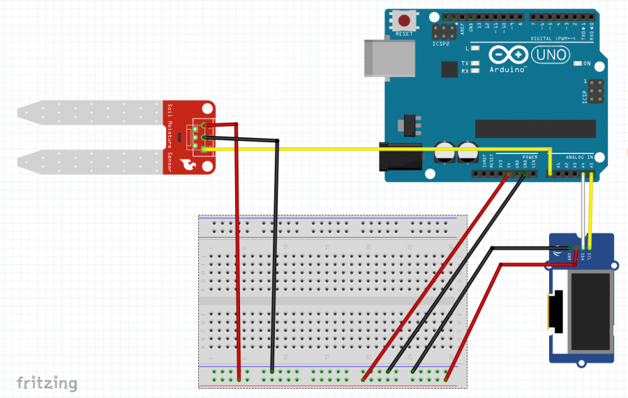
It is an analog sensor and we will connect the YELLOW wire to pin A0 of the Arduino uno.
The BLACK goes to GND
and the RED goest to 5V
#include <Wire.h>
#include <SeeedOLED.h>

void setup(){

  Serial.begin(9600);
  Wire.begin();                 //initialize I2C in master mode
  SeeedOled.init();             //initialize the OLED
  SeeedOled.clearDisplay();     //clear the screen and set start position to top left corner
  SeeedOled.setNormalDisplay(); //Set display to normal mode (i.e non-inverse mode)
  SeeedOled.setPageMode();      //Set addressing mode to Page Mode
}

void loop(){

  float sensorValue;
  sensorValue = analogRead(0);                        //connect the Moisture sensor to Analog 0


  Serial.println(sensorValue); //here we will be able to see the sensor value in the Serial monitor
  SeeedOled.setTextXY(1, 0);
  SeeedOled.putString("Sensing");
  SeeedOled.setTextXY(3, 0);
  SeeedOled.putString("Soil Moisture:");
  SeeedOled.setTextXY(5, 0);
  SeeedOled.putFloat(sensorValue);

}
UV sensor
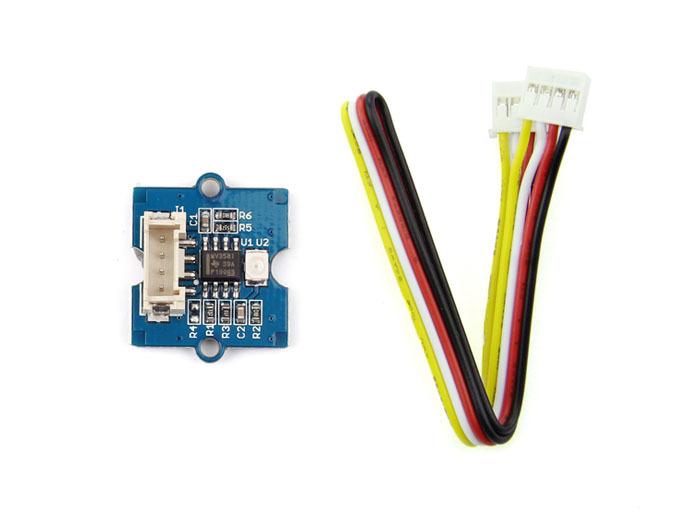
The Grove – UV Sensor is used for detecting the intensity of incident ultraviolet(UV) radiation. This form of electromagnetic radiation has shorter wavelengths than visible radiation. The Grove - UV Sensor is based on the sensor GUVA-S12D which has a wide spectral range of 200nm-400nm.
It is an analog sensor and we will connect the YELLOW wire to pin A0 of the Arduino uno.
The BLACK goes to GND
and the RED goest to 5V
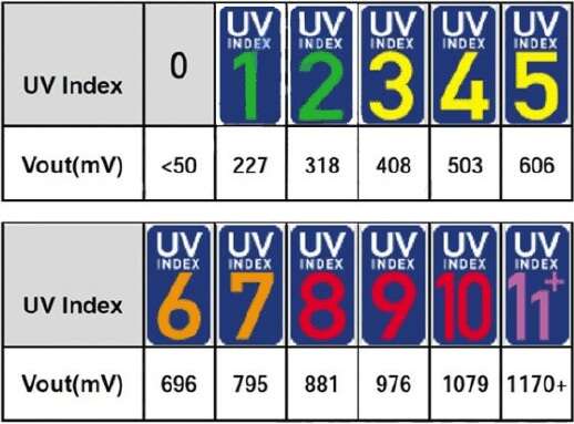
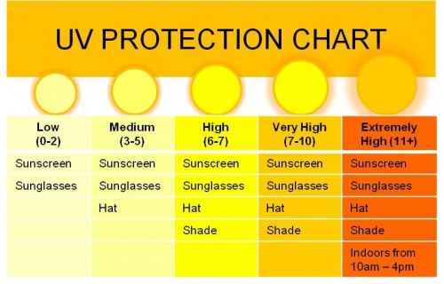
(* World Health Organisation Classification / Standard UV Index vs Sensor Module’s Output Voltage
#include <Wire.h>
#include <SeeedOLED.h>

void setup(){

  Serial.begin(9600);
  Wire.begin();                 //initialize I2C in master mode
  SeeedOled.init();             //initialize the OLED
  SeeedOled.clearDisplay();     //clear the screen and set start position to top left corner
  SeeedOled.setNormalDisplay(); //Set display to normal mode (i.e non-inverse mode)
  SeeedOled.setPageMode();      //Set addressing mode to Page Mode
}

void loop(){

  // String UVIndex = "0";
  int sensorValue = 0;
  float UVIndex = 0.0;
  sensorValue = analogRead(0);                        //connect UV sensor to Analog 0
  int voltage = (sensorValue * (5.0 / 1023.0))*1000;  //Voltage in miliVolts

  if(voltage<50)
  {
    UVIndex = 0.0;
  }
  else if (voltage>50 && voltage<=227)
  {
    UVIndex = 0.0;
  }
  else if (voltage>227 && voltage<=318)
  {
    UVIndex = 1.0;
  }
  else if (voltage>318 && voltage<=408)
  {
    UVIndex = 2.0;
  }
  else if (voltage>408 && voltage<=503)
  {
    UVIndex = 3.0;
  }
  else if (voltage>503 && voltage<=606)
  {
    UVIndex = 4.0;
  }
  else if (voltage>606 && voltage<=696)
  {
    UVIndex = 5.0;
  }
  else if (voltage>696 && voltage<=795)
  {
    UVIndex = 6.0;
  }
  else if (voltage>795 && voltage<=881)
  {
    UVIndex = 7.0;
  }
  else if (voltage>881 && voltage<=976)
  {
    UVIndex = 8.0;
  }
  else if (voltage>976 && voltage<=1079)
  {
    UVIndex = 9.0;
  }
  else if (voltage>1079 && voltage<=1170)
  {
    UVIndex = 10.0;
  }
  else if (voltage>1170)
  {
    UVIndex = 11.0;
  }


  Serial.println(voltage); //here we print the voltage the sensor ourputs in the Serial monitor
  SeeedOled.setTextXY(1, 0);
  SeeedOled.putString("Sensing");
  SeeedOled.setTextXY(3, 0);
  SeeedOled.putString("UV index:");
  SeeedOled.setTextXY(5, 0);
  SeeedOled.putFloat(UVIndex);  //print the UV index according to the voltage measured


}
Temperature Sensor
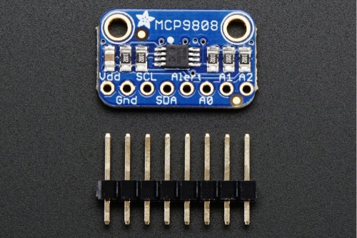
Adafruit MCP9808 Precision I2C Temperature Sensor
Temperature and humidity
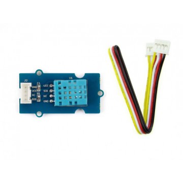
This Temperature&Humidity sensor provides a pre-calibrated digital output. A capacitive sensor element measures relative humidity and the temperature is measured by a negative temperature coefficient (NTC) thermistor. It has excellent reliability and long term stability. Please note that this sensor will not work for temperatures below 0 degree.
It is the only digital sensor we will be using
It is a digital sensor and we will connect the YELLOW wire to digital 2 pin of the Arduino uno.
The BLACK goes to GND
and the RED goest to 5V
We will have to install the Grove Temperature And Humidity Sensor library by Seeed studio and launch the DHT tester example.
And then, after we have tested the sensor, we will use the code for the sensor box
#include <DHT.h>
#include <Wire.h>
#include <SeeedOLED.h>

#define DHTPIN 2     // what pin we're connected to
#define DHTTYPE DHT11   // DHT 11
DHT dht(DHTPIN, DHTTYPE);

void setup() {

  Wire.begin();                 //initialize I2C in master mode
  SeeedOled.init();             //initialize the OLED
  SeeedOled.clearDisplay();     //clear the screen and set start position to top left corner
  SeeedOled.setNormalDisplay(); //Set display to normal mode (i.e non-inverse mode)
  SeeedOled.setPageMode();      //Set addressing mode to Page Mode
}

void loop() {
  float temp, hum;

  //Read temperature and humidity
  do {
    hum = dht.readHumidity();
    temp = dht.readTemperature();
  }
  while (isnan(temp) || isnan(hum));

  //Print temperature and humidity values on the OLED display
  SeeedOled.setTextXY(0, 0);
  SeeedOled.putString("Temperature:");
  SeeedOled.setTextXY(1, 0);
  SeeedOled.putString(String(temp).c_str());  //print temperature data converted to a c string
  SeeedOled.putString("C");
  SeeedOled.setTextXY(3, 0);
  SeeedOled.putString("Humidity:");
  SeeedOled.setTextXY(4, 0);
  SeeedOled.putString(String(hum).c_str());   //print humidity data converted to a c string
  SeeedOled.putString("%");

  delay(2000);
}
Air Quality
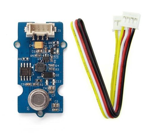
This sensor is designed for comprehensive monitor over indoor air condition. It's responsive to a wide scope of harmful gases, as carbon monoxide, alcohol, acetone, thinner, formaldehyde and so on. Due to the measuring mechanism, this sensor can't output specific data to describe target gases' concentrations quantitatively.
It is an analog sensor and we will connect the YELLOW wire to pin A0 of the Arduino uno.
The BLACK goes to GND
and the RED goest to 5V
/*
 * Grove_Air_Quality_Sensor.ino
 * Demo for Grove - Air Quality Sensor.
 *
 * Copyright (c) 2019 seeed technology inc.
 * Author    : Lets Blu
 * Created Time : Jan 2019
 * Modified Time:
 *
 * The MIT License (MIT)
 *
 * Permission is hereby granted, free of charge, to any person obtaining a copy
 * of this software and associated documentation files (the "Software"), to deal
 * in the Software without restriction, including without limitation the rights
 * to use, copy, modify, merge, publish, distribute, sublicense, and/or sell
 * copies of the Software, and to permit persons to whom the Software is
 * furnished to do so, subject to the following conditions:
 *
 * The above copyright notice and this permission notice shall be included in
 * all copies or substantial portions of the Software.
 *
 * THE SOFTWARE IS PROVIDED "AS IS", WITHOUT WARRANTY OF ANY KIND, EXPRESS OR
 * IMPLIED, INCLUDING BUT NOT LIMITED TO THE WARRANTIES OF MERCHANTABILITY,
 * FITNESS FOR A PARTICULAR PURPOSE AND NONINFRINGEMENT. IN NO EVENT SHALL THE
 * AUTHORS OR COPYRIGHT HOLDERS BE LIABLE FOR ANY CLAIM, DAMAGES OR OTHER
 * LIABILITY, WHETHER IN AN ACTION OF CONTRACT, TORT OR OTHERWISE, ARISING FROM,
 * OUT OF OR IN CONNECTION WITH THE SOFTWARE OR THE USE OR OTHER DEALINGS IN
 * THE SOFTWARE.
 */
#include "Air_Quality_Sensor.h"
#include <Wire.h>
#include <SeeedOLED.h>

AirQualitySensor sensor(A0);

void setup() {

  Serial.begin(9600);
  Wire.begin();                 //initialize I2C in master mode
  SeeedOled.init();             //initialize the OLED
  SeeedOled.clearDisplay();     //clear the screen and set start position to top left corner
  SeeedOled.setNormalDisplay(); //Set display to normal mode (i.e non-inverse mode)
  SeeedOled.setPageMode();      //Set addressing mode to Page Mode

  Serial.begin(9600);
  while (!Serial);
  SeeedOled.setTextXY(2, 0);
  SeeedOled.putString("Waiting sensor");
  SeeedOled.setTextXY(3, 0);
  SeeedOled.putString("to init...");
  delay(20000);

  if (sensor.init()) {

    SeeedOled.clearDisplay();     //clear the screen and set start position to top left corner
    Serial.println("Sensor ready.");
    SeeedOled.setTextXY(2, 0);
    SeeedOled.putString("Sensor ready.");
    delay(1000);
    SeeedOled.clearDisplay();     //clear the screen and set start position to top left corner

  }
  else {
    Serial.println("Sensor ERROR!");
  }
}

void loop(void) {
  int quality = sensor.slope();
  SeeedOled.setTextXY(1, 0);
  SeeedOled.putString("Sensing");
  SeeedOled.setTextXY(2, 0);
  SeeedOled.putString("Air Quality:");
  Serial.print("Sensor value: ");
  Serial.println(sensor.getValue());

  if (quality == AirQualitySensor::FORCE_SIGNAL) {
    SeeedOled.setTextXY(4, 0);
    SeeedOled.putString("High pollution! Force signal active.");
  }
  else if (quality == AirQualitySensor::HIGH_POLLUTION) {
    SeeedOled.setTextXY(4, 0);
    SeeedOled.putString("High pollution!");
  }
  else if (quality == AirQualitySensor::LOW_POLLUTION) {
    SeeedOled.setTextXY(4, 0);
    SeeedOled.putString("Low pollution!");
  }
  else if (quality == AirQualitySensor::FRESH_AIR) {
    SeeedOled.setTextXY(4, 0);
    SeeedOled.putString("Fresh air.");
  }

  delay(500);
}
Gyroscope/Accelerometer
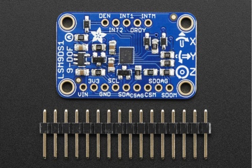
Adafruit 9-DOF Accel/Mag/Gyro+Temp Breakout Board - LSM9DS1
Gyroscope/acceleration meter:library and tutorial
