Motors: Introduction and Types
Motors
!!! WATCH THIS / very nice video from the Prelinger Archives, the motor part starts at 06:12
DC motors
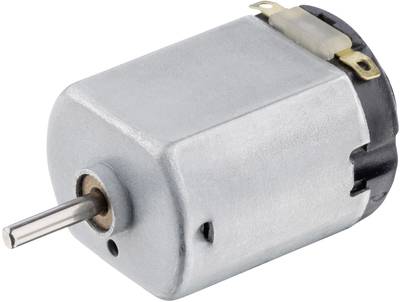
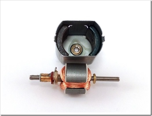
DC (Direct Current) motors are two wire (power & ground), continuous rotation motors. When you supply power, a DC motor will start spinning until that power is removed. Most DC motors run at a high RPM (revolutions per minute).
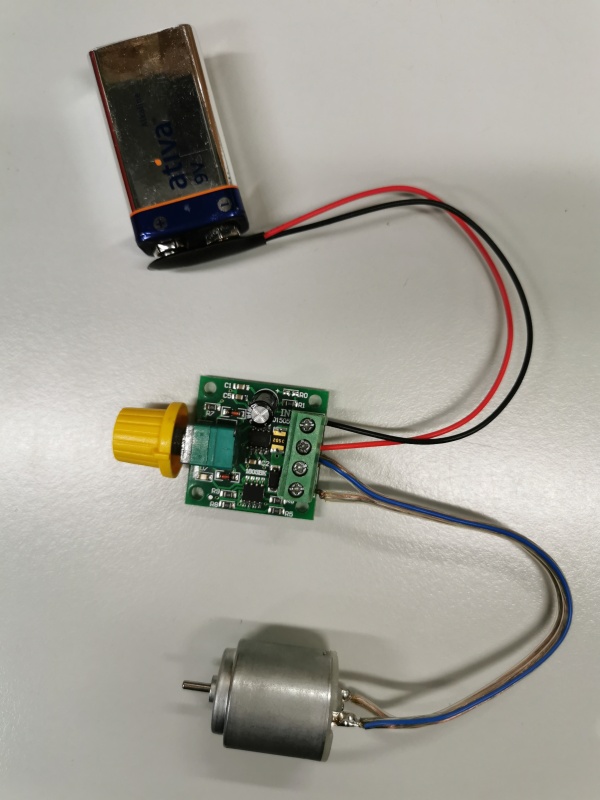
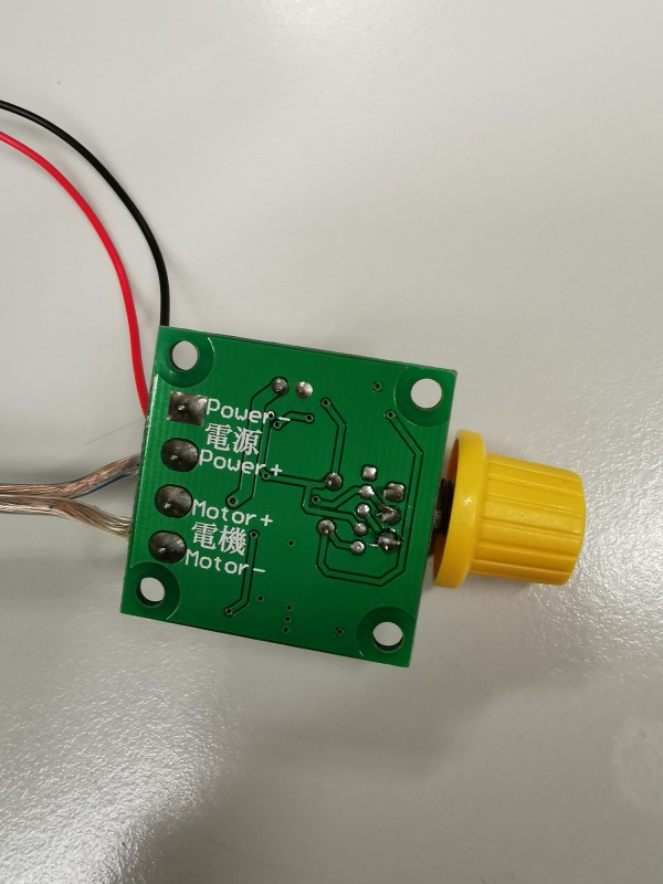
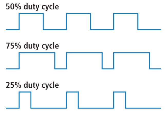
The speed of DC motors is controlled using pulse width modulation (PWM), a technique of rapidly pulsing the power on and off. The percentage of time spent cycling the on/off ratio determines the speed of the motor, e.g. if the power is cycled at 50% (half on, half off), then the motor will spin at half the speed of 100% (fully on). Each pulse is so rapid that the motor appears to be continuously spinning with no stuttering!
PWM examples of duty cycles
servo motors
Servo motors are basically more flavored Dc motors.
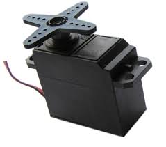
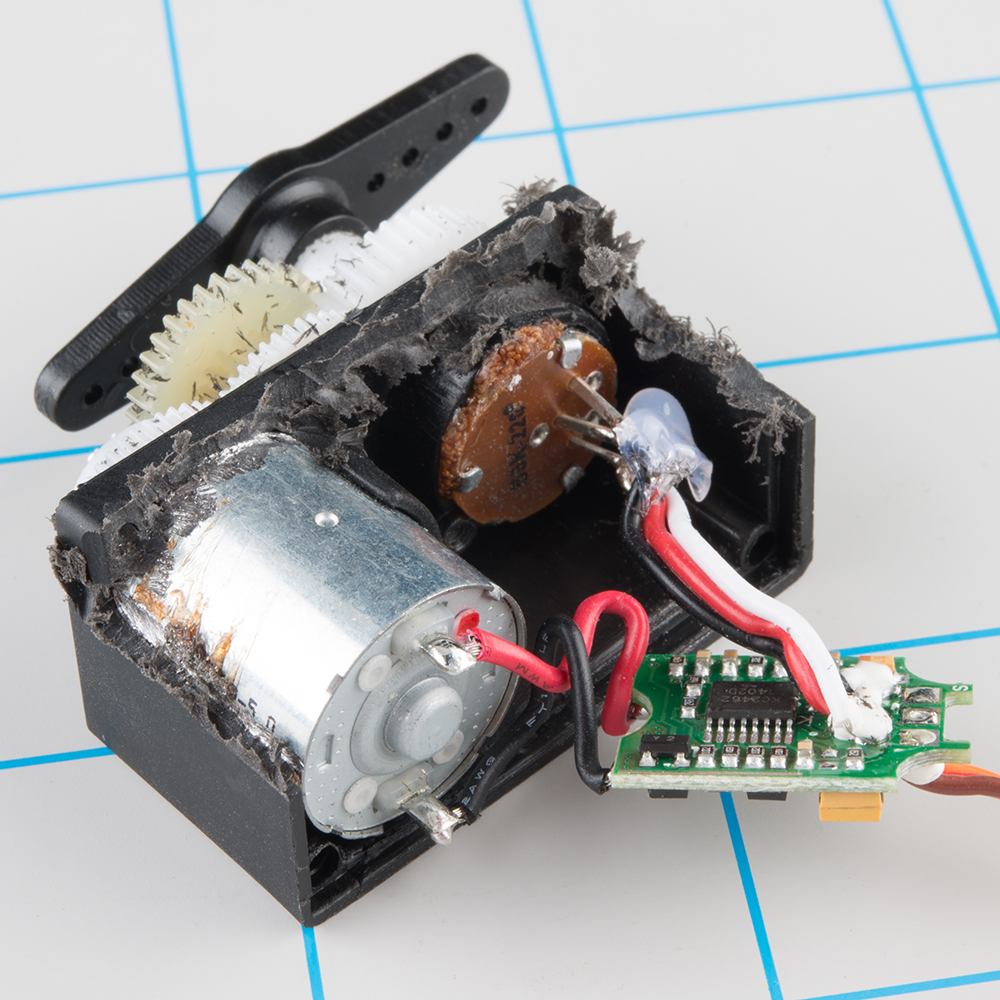
They are generally an assembly of four things: a DC motor, a gearing set, a control circuit and a position-sensor (usually a potentiometer).
The position of servo motors can be controlled more precisely than those of standard DC motors, and they usually have three wires (power, ground & control). Power to servo motors is constantly applied, with the servo control circuit regulating the draw to drive the motor.
Servo motors do not rotate freely like a standard DC motor. Instead the angle of rotation is limited to 180 Degrees back and forth. Servo motors receive a control signal that represents an output position and applies power to the DC motor until the shaft turns to the correct position, determined by the position sensor.
PWM is used for the control signal of servo motors. However, unlike DC motors it’s the duration of the positive pulse that determines the position, rather than speed, of the servo shaft. A neutral pulse value depending on the servo (usually around 1.5ms) keeps the servo shaft in the center position. Increasing that pulse value will make the servo turn clockwise, and a shorter pulse will turn the shaft anticlockwise. The servo control pulse is usually repeated every 20 milliseconds, essentially telling the servo where to go, even if that means remaining in the same position.
stepper motors
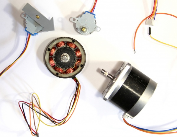
A stepper motor is essentially a servo motor that uses a different method of motorization. Where a servo motor uses a continuous rotation DC motor and integrated controller circuit, stepper motors use multiple toothed electromagnets arranged around a central gear to define position.
Stepper motors require an external control circuit or micro controller (for instance a Raspberry Pi or Arduino) to individually energize each electromagnet and make the motor shaft turn. When electromagnet ‘A’ is powered it attracts the gear’s teeth and aligns them, slightly offset from the next electromagnet ‘B’. When ‘A’ is switch off, and ‘B’ switched on, the gear rotates slightly to align with ‘B’, and so on around the circle, with each electromagnet around the gear energizing and de-energizing in turn to create rotation. Each rotation from one electromagnet to the next is called a "step", and thus the motor can be turned by precise predefined step angles through a full 360 Degree rotation.
Stepper motors are available in two varieties; unipolar or bipolar. Bipolar motors are the strongest type of stepper motor and usually have four or eight leads. They have two sets of electromagnetic coils internally, and stepping is achieved by changing the direction of current within those coils. Unipolar motors, identifiable by having 5,6 or even 8 wires, also have two coils, but each one has a center tap. Unipolar motors can step without having to reverse the direction of current in the coils, making the electronics simpler. However, because the center tap is used to energize only half of each coil at a time they typically have less torque than bipolar.
The design of the stepper motor provides a constant holding torque without the need for the motor to be powered and, provided that the motor is used within its limits, positioning errors don't occur, since stepper motors have physically predefined stations.
Resources
RPM
stepper motors, controlled via a micro controller are easy to follow at what rpm they operate, and to be adjusted e with dc motors, it is a fixed rpm with a small torque, at which the motor operates, and in order to adjust this, gear systems, pulleys .....there is more
Making things move is a book, very useful, please download it and look especially into Forces, Friction, and Torque (Oh My!) starting page 73 and then The Guts: Bearings, Couplers, Gears, Screws, and Springs page 189 till the end But also check out the website for useful bits and pieces
Basic mechanisms
briefly some basic mechanisms
Levers
a lever is a rigid object with pivot point used to multiply the mechanical force of an object
it has input – pivot point-output
examples: seesaw hammer when removing nails crowbar also
Cranks
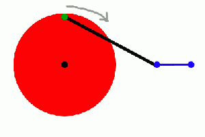
A crank is simply an off-center connection that provides energy to (or takes energy from) a rotating wheel.
Slider crank mechanisms
he crank slider turns a circular motion in an oscillating movement and a vertical movement. The larger the distance between the wheel and the plane green brown, the lower the oscillation of the highest point of the red stick
Crankshaft
The cam piston transforms a circular motion in a vertical movement. The larger the diameter of the wheel, the greater the vertical stroke of the red stick.
Linkages
we can use extra motion ( for exmple from a crank) to add extra movement
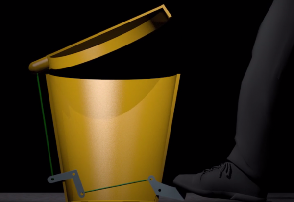
A linkage can be made from levers, cranks and connecting elements. They are use to change direction or amount of motion
Cams
Cams generally do the opposite job to cranks: they turn rotary motion into reciprocating motion.
Eccentric cam
The eccentric cam transforms a circular motion in a vertical movement. the vertical excursion of the red stick changes as a function of the varying diameter of the cam.
Jumping Cam
The shape of the cam creates a jump during the movement of the red stick. In this way can produce abrupt and sudden movements.
Shafts
Ratchets
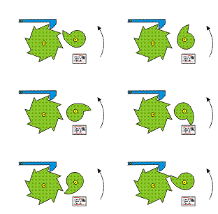
can be used to give intermittent or stepped motion. Also used to give rotation in one direction only
The cam rotates the large wheel of an eighth for each revolution. The blue slider prevents the large wheel can turn in the opposite.
Gearing
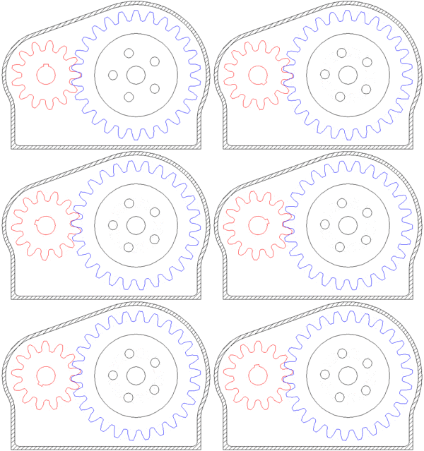
A gear or cogwheel is a rotating machine part having cut teeth, or cogs, which mesh with another toothed part to transmit torque.
Geared devices can change the speed and power delivered.
GEAR RATIO
two gears, one half as big as the other, have a gear ratio of 2:1. The smaller gear has to spin twice to cover the same distance covered when the larger gear spins once.
Drives
A drive is a method of connection rotation shafts together
the drive can involve gearing, changing direction or rotation of the shafts.
A bike chain is a POSITIVE DRIVE ...it cannot slip ( it is kept locked to the sprocket wheel ) , while wheels slip if they are under resistance ( break) and they stop turning, that is FRICTION, pulleys also work by friction.
A short/rapid exercise
The multitudes
everyone will make a simple motor/ball system and together those will create harmony from chaos
