Difference between revisions of "Swatch Making"
| Line 258: | Line 258: | ||
The schema of the circuit: https://cdn.makezine.com/uploads/2014/08/555ss_bboard_4-3-ratio_annotation.png | The schema of the circuit: https://cdn.makezine.com/uploads/2014/08/555ss_bboard_4-3-ratio_annotation.png | ||
| − | [[File:sf1.png| | + | [[File:sf1.png|100px]] |
The circuit on the breadboard. | The circuit on the breadboard. | ||
| − | [[File:sf2.png| | + | [[File:sf2.png|400px]] |
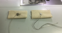
Three versions of a soft speaker. To the left: copper wire, in the middle, spiral of copper sheet cut with a lino cutter. To the right the conductive metal wire. The problem with this is that the metal "sticks" to the magnets. | Three versions of a soft speaker. To the left: copper wire, in the middle, spiral of copper sheet cut with a lino cutter. To the right the conductive metal wire. The problem with this is that the metal "sticks" to the magnets. | ||
Revision as of 20:59, 30 April 2020
in progress
intro
Making swatches for e-textiles.
The goal is to provide examples for simple and more advanced circuits on fabric.
The possibilities to make "soft" versions of electronic components like switches and battery holders.
preperation
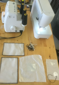
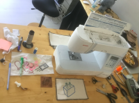
Table with tools
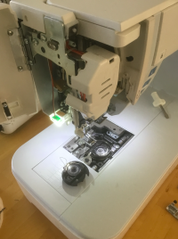
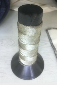
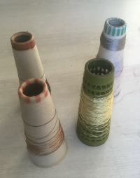
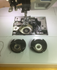
Putting a special spool with conductive thread inside the sewing machine.
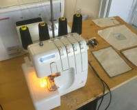
Lock Machine
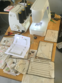
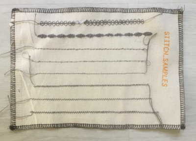
Table with swatches
tools
Machines
- Sewing machine
- lock machine
- soldering station
- scissors
- needles
- stitch undo tool
electronics
- leds
- coin cell batteries
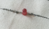
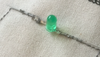
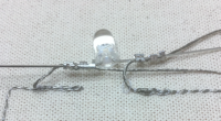
led conductive thread connection
Connecting the legs of the LED to the thread is always a bit of a problem.
There is a method making an eyelet of the leg of the LED and knotting the thread.
I trepide out a new way for me, with a small clamp:
materials
- non conductive materials
- conductive materials
- vlisofix plus aluminium foil
conductive threads
There are many different conductive threads. Some like the Karl Grimm silver thread can be soldered. Most others, which have a plastic kernel cannot be soldered.
For using conductive thread in my Janome sewing machine I have to change the bobbin holder. I then can put the stainless steel conductive thread in the spool.
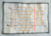
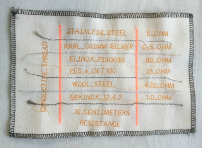
All conductive threads have different properties. The most important property for the use in a circuit is the resistance. The resistance of a conductive thread can vary from very little (say less then 1 Ohm every 10 centimeters) to very high resistance, sometimes even kOhm or mOhm.
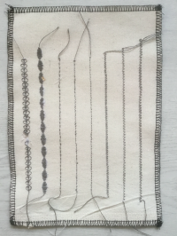
One of the swatches shows 6 different conductive threads.
On school we only have the stainless steel, which consists of steel fibers around plastic fibers. When you wash this thread it gets corroded, and will break down.
Many conductive threads can only be bought industrially and are not available for small consumers.
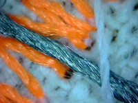
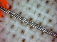
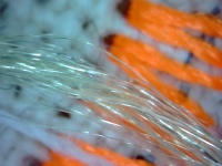
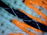
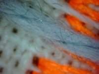
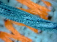
It is interesting to look at the conductive thread under the USB microscope, then you get a better understanding of the structure of the materials and you can understand why some of these threads break down easily.
Copper wire
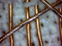
This is used for winding coils. It is isolated, although you "see" the copper. It is called enamelled copper wire. To be able to solder or connect this wire you have to scrape the enamel from the wire, using a knife or sand paper.
The enamel and the copper can be seen in this picture. The wire in the coil had to be repaired, it had to be scraped to be able to solder it.
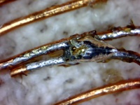
The soldering material will only stick where the enamel is removed. Here the soldiered joint can be seen under the usb-microscope.
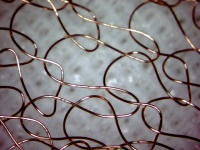
That is why in a knitting of this wire, there is not a short-cut (if the enamel is not damaged).
ideas
- fabric battery holder
- making a circuit
- connecting a LED
- making a textile switch
Failures
I especially also add the failures. Otherwise it would seem that everything fitted without any effort, which is not true. Sometimes failures are more interesting than results. Failures do keep you moving while results are finished - dead.
From these what we call errors you learn the most. For example, I thought I would get a better connection by making the stitch length smaller. But then the stitching on the heavy material gets irregular.
That induced me making a swatch of the different stitch length. It turned out that the default stitch length of the machine 2.4 mm was the best. I also tried out some decorative stitches, and the zig zags.
Starting to add embroidery, things got wrong. This is the material which reminds you of the difference between your lofty ideas and the materials. If everything would go smooth and without any hiccups, no jumps would be made, everything would remain the same. Jumps on the other hand cost time. Maybe time is being made by the failures and the jumps.
Starting embroidery combined with conductive thread, things didn't came together...
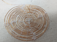
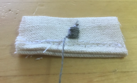
The loop in the wire of the fabric speaker....somehow, in the middle of the windings, a loop was formed at the other side of the fabric, resulting in 2 cm of wire which had to be removed.
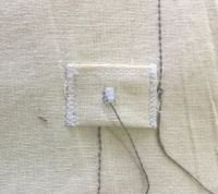
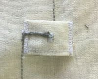
fabric battery holder
The last battery holder I made functioned, but is was also a bit inconvenient, because it was cumbersome to get the coin cell out. It was too stiff and has only one entrance.
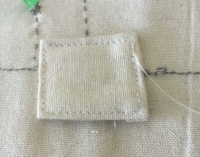
Therefore I designed another way, a battery holder with two sides open. The base fabric holds a pattern of conductive thread and is for the larger + side of the battery. The fabric on top has a nudge of conductive material that pushes on the - side of the battery. There is of course a loop going on the outside to the minus, preventing a short cut.
nudge on top of the fabric made with a zig zag three times on top of it.
With a needle the wire has to be pushed through the material, otherwise there will be a short cut.
Placing the upper side of the fabric battery holder.
The piece is sewn on the base fabric using a zig zag, so that we don't have to fold the side again.
Connecting the wire to the wire of the circuit.
Intermediate stages
Because the sewing machine has a special spool cylinder for the conductive thread installed, the fabric battery holders have to be made later.
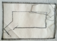
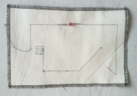
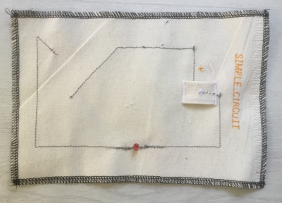
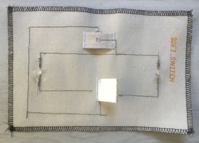
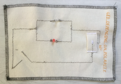
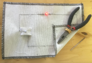
Simple circuit, with one LED. The corner fold is the switch.
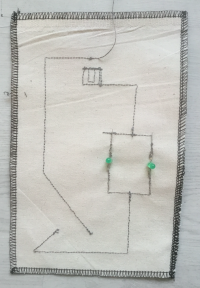
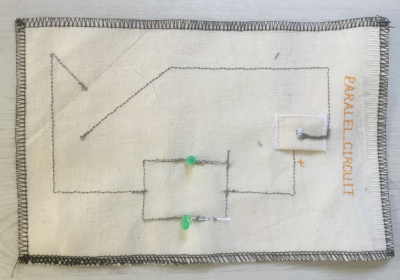
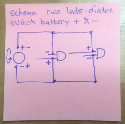
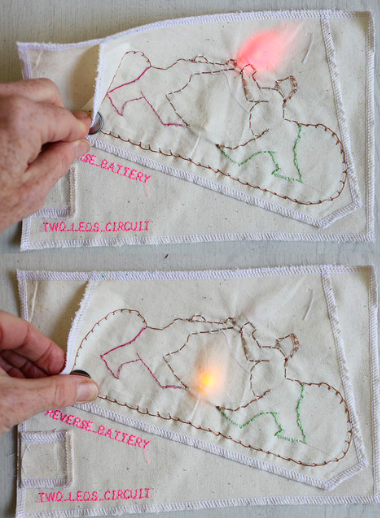
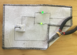
Circuit with two LED's in parallel.
results
Swatches with conductive thread.
Swatches about circuits
Testing the simple circuit
Testing the parallel circuit.
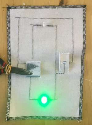
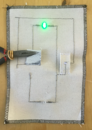
A Fabric Switch
The Soft speaker
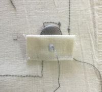
A soft speaker can be built, by using conductive wire and a magnet, in combination with a 555 timer circuit with LDR, with a 9V battery.
The sound is really soft! The tone is varying according to the light on the LDR.
The schema of the circuit: https://cdn.makezine.com/uploads/2014/08/555ss_bboard_4-3-ratio_annotation.png
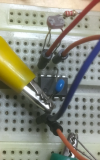
The circuit on the breadboard.
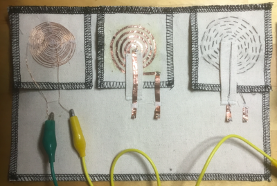
Three versions of a soft speaker. To the left: copper wire, in the middle, spiral of copper sheet cut with a lino cutter. To the right the conductive metal wire. The problem with this is that the metal "sticks" to the magnets.
