Swatch Making
in progress
intro
See the e-swatches on Fashion Tech Farm tiktok!
swatch tiktok 1: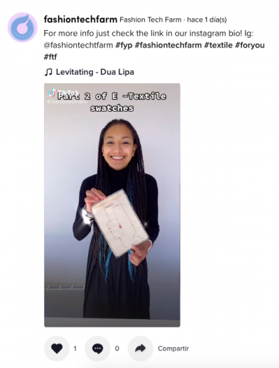
swatch tiktok 2:
Making swatches for e-textiles.
The goal is to provide examples for simple and more advanced circuits on fabric.
The possibilities to make "soft" versions of electronic components like switches and battery holders.
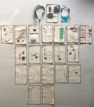 The collection of swatches

preperation

Table with tools

Putting a special spool with conductive thread inside the sewing machine.

Lock Machine

Table with swatches
tools
Machines
- Sewing machine
- lock machine
- soldering station
- Knitting Machine
Smaller tools
- scissors
- needles
- stitch undo tool
- plyers
- needles
- magnifying glasses
electronics
- leds
- coin cell batteries
- TFT screen
microcontrollers
- ATtiny85
- Arduino Pro Mini
Sensors
- light LDR
- soft membrane
- push sensor
- temperature sensor
- BME680 - gas, barometric, temperature
- ADXL345 accelration
Special E-textile applications
- knitted pull sensor
- fabric speaker
- fabric breadboard
- lace
- soft button
- fabric folds
- fabric screen container
led conductive thread connection
Connecting the legs of the LED to the thread is always a bit of a problem.
There is a method making an eyelet of the leg of the LED and knotting the thread.
I trepide out a new way for me, with a small clamp:


materials
- non conductive materials
- conductive materials

- vlisofix plus aluminium foil
conductive threads
There are many different conductive threads. Some like the Karl Grimm silver thread can be soldered. Most others, which have a plastic kernel cannot be soldered.

For using conductive thread in my Janome sewing machine I have to change the bobbin holder. I then can put the stainless steel conductive thread in the spool.

All conductive threads have different properties. The most important property for the use in a circuit is the resistance. The resistance of a conductive thread can vary from very little (say less then 1 Ohm every 10 centimeters) to very high resistance, sometimes even kOhm or mOhm.
One of the swatches shows 6 different conductive threads.

On school we only have the stainless steel, which consists of steel fibers around plastic fibers. When you wash this thread it gets corroded, and will break down.
Many conductive threads can only be bought industrially and are not available for small consumers.
It is interesting to look at the conductive thread under the USB microscope, then you get a better understanding of the structure of the materials and you can understand why some of these threads break down easily.

|

|

|

|

|

|
| conductive thread 1: Stainless Steel, 4 ply, the school material. | conductive thread 2: Karl Grimm, can be soldered, silver, head to get, the least resistance | conductive thread 3: Elinox, high resistance. | conductive thread 4: Pes Det, the winding of the conductive metal is very conspicuous | conductive thread 5: Wool NM 1013 + steel, lots of wool and the single steel fibers, in this sample most of the resistance | conductive thread 6: Bekinox, feels very heavy |
| resistance: 5.0 Ohm per 10 centimeters of the sample | resistance: 0.5 Ohm per 10 centimeters of the sample | resistance: 90 Ohm per 10 centimeters of the sample | resistance: 18 Ohm per 10 centimeters of the sample | resistance: 420 Ohm per 10 centimeters of the sample | resistance: 1.0 Ohm per 10 centimeters of the sample |
The problem of the conductive yarn is that it is only available in industrial quantities. The only bigger spool for sale commercially (for us) is the sticky metal conductive: https://www.kiwi-electronics.nl/sf-dev-11791, otherwise you have to buy bobbins of 10 meter or so: https://www.floris.cc/shop/en/wearables/932-stainless-thin-conductive-thread-2-ply-23-meter.html
Copper wire
This is used for winding coils. It is isolated, although you "see" the copper. It is called enamelled copper wire. To be able to solder or connect this wire you have to scrape the enamel from the wire, using a knife or sand paper.
|
The enamel and the copper can be seen in this picture. The wire in the coil had to be repaired, it had to be scraped to be able to solder it.
|
The soldering material will only stick where the enamel is removed. Here the soldiered joint can be seen under the usb-microscope.
|
That is why in a knitting of this wire, there is not a short-cut (if the enamel is not damaged).
links to shops: (currently...)
At floris.cc: https://www.floris.cc/shop/en/home/2105-conductive-thread-60g-stainless-steel.html
I bought the sticky conductive metal at KIWI: https://www.kiwi-electronics.nl/sf-dev-11791?search=conductive&description=true
I saw "anti static" and conductive wool at Bart and Francis: https://www.bart-francis.be/index.php?action=search&lang=NL&srchval=conductive
Failures
I especially also add the failures. Otherwise it would seem that everything fitted without any effort, which is not true. Sometimes failures are more interesting than results. Failures do keep you moving while results are finished - dead.
From these what we call errors you learn the most. For example, I thought I would get a better connection by making the stitch length smaller. But then the stitching on the heavy material gets irregular.

That induced me making a swatch of the different stitch length. It turned out that the default stitch length of the machine 2.4 mm was the best. I also tried out some decorative stitches, and the zig zags.

Starting to add embroidery, things got wrong. This is the material which reminds you of the difference between your lofty ideas and the materials. If everything would go smooth and without any hiccups, no jumps would be made, everything would remain the same. Jumps on the other hand cost time. Maybe time is being made by the failures and the jumps.

Starting embroidery combined with conductive thread, things didn't came together...
The loop in the wire of the fabric speaker....somehow, in the middle of the windings, a loop was formed at the other side of the fabric, resulting in 2 cm of wire which had to be removed.

fabric battery holder
The last battery holder I made functioned, but is was also a bit inconvenient, because it was cumbersome to get the coin cell out. It was too stiff and has only one entrance.

Therefore I designed another way, a battery holder with two sides open. The base fabric holds a pattern of conductive thread and is for the larger + side of the battery. The fabric on top has a nudge of conductive material that pushes on the - side of the battery. There is of course a loop going on the outside to the minus, preventing a short cut.

nudge on top of the fabric made with a zig zag three times on top of it.

With a needle the wire has to be pushed through the material, otherwise there will be a short cut.

Placing the upper side of the fabric battery holder.

The piece is sewn on the base fabric using a zig zag, so that we don't have to fold the side again.

Connecting the wire to the wire of the circuit.
Intermediate stages
Because the sewing machine has a special spool cylinder for the conductive thread installed, the fabric battery holders have to be made later.

Simple circuit, with one LED. The corner fold is the switch.

Circuit with two LED's in parallel.
results - testing conductive thread

|

|
| The first swatch is trying out the conductive thread, as can be seen, in plain stitching, when the stitch length is too small, the stitch gets irregular at this fabric. | Sample swatch for different conductive threads. Description above. |
results - Swatches about circuits

|

|

|
| A simple circuit. In an electronic sense, this is very simple. For e-textiles, there are already problems to be solved, like sewing the conductive thread and the soft battery holder. | A Parallel circuit. To be able to make two LED's shine, both LED's must be connected to the plus and the minus. E-textile problems: connecting the conductive wire by sewing. | A switch circuit. With the with made of fabric and aluminium foil either the right or the left LED can be chosen. |

|

|

|
| This circuit exploits the fact that the coin cell battery can be inserted in two ways and that the LED is a diode. Depending on the orientation of the battery either the blue or the red LED will light up. | schema of the two led-diodes. It is the basics for Charlie Plexing circuits, where there are more LED's connected to a microcontroller than free legs available. | This effect can be used for story telling, as is shown in this swatch. The men either fight with their fists or kick with their feet. |

Testing the simple circuit

Testing the parallel circuit.


A Fabric Switch
Results: Testing Lilypad LED's
A swatch with 7 different SMD LED's on special boards for sewing on fabric.
The Lilypad is an Arduino on a nice circular board, especially designed for e-textile applications.
The LED's can be bought here for example: https://www.floris.cc/shop/en/wearables/104-lilypad-led-blue-5pcs-.html
The fun of the different colors is not only the color, but also that the different colors are related with different currents, at the same Voltage.
The current is not related to the brightness! Caring about the current is important in projects where long battery life is important.


With the two crocodile clips the different LED's can be compared.
In general the current drawn by any LED's can be very different, so when using a battery, it is important to check and compare.
The energy used is equal to Voltage times Current: P = V * I. The energy of a battery is fixed. So when an LED is using 50 mA or 5 mA makes the project with the second LED run 10 times longer than the project with the first LED in a rough approximation.
Result: different LED's parallel
There is another effect of this difference in current that two different colored LED's use. When both a connected tot he same battery only one will get the energy! So testing the LED's separately on this battery will have them "on", but connect both to these battery together, then only one will take all energy! The current will go to the LED with the least resistance.

The green LED, when connected parallel with the white LED, is "eating" all the current, thus putting off the white LED.
This effect can be seen here: https://www.flickr.com/photos/contrechoc/49957335202/in/dateposted/
The green LED is using three times as much current as the white LED, although the white LED is much brighter.
results - The Soft speaker
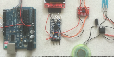
A soft speaker can be built, by using conductive wire and a magnet, in combination with a 555 timer circuit with LDR, with a 9V battery.
The effect of the sound in the fabric is rather soft, so therefore the 555 is used which can operate with the higher voltage of 9V.
The sound is really soft! The tone is varying according to the light on the LDR.
The schema of the circuit: https://cdn.makezine.com/uploads/2014/08/555ss_bboard_4-3-ratio_annotation.png

The circuit on the breadboard.
See also: https://www.kobakant.at/DIY/?p=3652
Failure
So I made three versions of the soft speaker on one swatch. That made things rather complex. Connecting the one 555 timer circuit conveniently and comprehensibly to the three speakers for testing is already a problem.

Three versions of a soft speaker. To the left: copper wire, sewn on the fabric, in the middle, spiral of copper sheet cut with a lino cutter. To the right the conductive metal wire, embroidered on the fabric. The problem with this is that the metal "sticks" to the magnets.
So I decided this was a failure, and made a new one with only one: the enameled copper wire. This is now much simpler and shows the principle. The only problem remaining is how to sew the copper wire to the fabric. I tried several ways. This swatch is not really the most beautiful solution.
 Two together.
 Final version, the sewing is still a mess.
results - 7 LED's in Folding
(still some details, like embroidering the title on the swatch, have to be done)
Using the folds of fabric to hide the LED's and to get the light of the LED's reflected from the surface.
Microcontroller: ATTiny85, with 5 I/O pins, and 7 LED's so using Charlieplexing. This circuit runs at 3V.
The ATtiny85 can be programmed simple within the Arduino environment, using the ATtiny plugins.
The code can be found here: https://github.com/contrechoc/charlieplexed-swatch
 front
front
 back
back
Illuminated Lace
Using 8 LED's on 4 PIN's of the ATtiny85 as a backlight for a lace.
With a fabric battery holder and a switch inside fabric.
 without the lace covering


The script can be found here: ....somewhere!
Joule Thief
The Joule thief uses a boost circuit for making 3V from a 1.5V battery.
The battery holder is using aluminium foil on fabric to do two things: it serves as a battery holder and it serves as the switch. The LED starts when the conductive pieces are pushed against the plus and minus of the battery.
The schema for a Joule Thief can be found on many places, for instance: https://diyteach.wordpress.com
The most tricky step is the winding and connecting the wires around the ferro toroid: here you find a clear image: https://www.instructables.com/id/Itty-Bitty-Joule-Thief/

more info can be found here: http://interactionstation.wdka.hro.nl/wiki/Energy_for_Designers#Week_1_-_Day_2
results - fabric and TFT screen
Examples/intro
For more advanced applications electronic components have to be sewn into the fabric.
Different small screens are available, like LCD (one color) and TFT (color).
 LCD screen, only some text and numbers. It can be used for data, like the temperature "at that moment". This means you cannot show the change in temperature during a longer time in a graph.
For displaying data, graphs (say the temperature during a day) and pictures a small TFT screen can be used. The TFT screen has "pixels" line 160 x 128, and fonts, and an sd-card to store images.
 Some examples, the data are clear, the left: the three circles are representing R - G - B data of the incoming light. The circles are always touching, the radius is the number, this is a small algorithm. The middle is "art" the data are noised by the colored squares, the resulting image is a bit more than boring numbers, the right is a bar chart.
 Some examples, a graph can be seen, changing in time, boring numbers and a representation of a sensor array at the right.
You could fit the screen on the fabric without any support - just sew it with threads.


An application:
 Project Laboratoire Aeroporté, 2019, Paillard, Poncé-sur-le-Loir
 Project Laboratoire Aeroporté, 2019, Paillard, Poncé-sur-le-Loir
Making a Fabric window
For other applications the components have to find a place inside the fabric and have to be supported by the fabric.

This simple way to cut a rectangle in for example paper is not giving a nice result in fabrics.

Another way to construct a window must be developed. Other solutions are possible, depending on your virtuosity with fabrics.

Also the electronics becomes more complex, with many wires. Here "normal" electrical wires are used, not the conductive thread. With too many wires, and batteries and many components the wires have to be isolated.

Some pictures of the result.

Pictures can be shown, or graphical representations, like graphs with data.

Remarks: I used here "another" and cheaper TFT screen. Normally with the libraries of Adafruit these screens will be running in no time. Of course around 10 wires must be soldered between the TFT screen and the microcontroller. But this other screen had some other properties. So it took me a few hours to figure out what was "different" or which wires were sewn wrongly. In the end it turned out to be the backlight of the screen which must be used, an extra LED connection. Also it can be seen in the pictures that the SD card is the bigger size, while the Adafruit TFT already uses the micro sd-card. So it can be that I saved a few euro's but then you have to be prepared for other characteristics or "retro" parts...
In all making this part of a swatch took me way longer than expected, the searching for the right way to use the TFT screen, and the development of the fabric window. Then the connection to the Lipo battery, with a switch, the programming and finding and making your own pictures, besides making graphs if data are displayed. The problem is also that your brains have to switch between many specifications, like sewing, electronics, programming, how to display data etc. This makes it practically impossible to do all in one day.
Variable Resistance Knitting
A knitted tube from conductive thread or a combination of yarn and conductive thread can make a variable resistor. Depending on the ind of conductive thread the total resistance will vary when the tube is pulled out. The exact mechanism is the "touching" of the thread over the knitted loops. When pulled, the loops will be connecting more tightly, making the resistance lower.
Some values:
- smooth metal wire tube: from 2 Ohm to 1 Ohm (so not too much variability)
- Conductive wool: from 48 kOhm to 100 Ohm
- Conductive metal thread with sticky metal conductive thread 50 Ohm - 4 Ohm.
 Knitting a tube with red yarn and grey metal conductive thread
 The three different tubes, top: smooth metal conductive, middle: sticky metal conductive with red yarn, bottom: conductive wool thread
 More tubes, with different yarn combinations, and the values.
See more details here: http://interactionstation.wdka.hro.nl/wiki/ResistanceKnitting
The swatch will contain an ATtiny85 with two led's. The second one will light up if the knitting is pulled. Depending on the resistance of the tube, there must be a second fixed resistor in the circuit, which has a middle value. The the analog PIN can be read and the microcontroller can see if the knitted tube is pulled.
Pull sensor from knitted conductive wool
Using an ATtiny85 with a voltage divider.
The conductive wool, knitted into a tube has a nice range of resistance when pulled: relaxed, 500K Ohm, pulled 50 Ohm.
With a resistor of 2K Ohm, and the appropriate scripting, this is a reliable pull sensor.
Script: https://github.com/contrechoc/swatches/blob/master/knitted_pull_sensor
Application: breathing sensor, in a band around the chest. Bending sensor for the arm, situated on the elbow.

SoftPotMembrane
An example of adding electronic components to fabric. The only "soft" part is the membrane but even this is relatively "hard".
Microcontroller: ATtiny85 - 8Mhz, + speaker 3V coin cell battery
SoftPot Membrane Potentiometer - 50mm
https://www.floris.cc/shop/en/flex-force/740-softpot-membrane-potentiometer-50mm.html
Datasheet membrane: https://www.sparkfun.com/datasheets/Sensors/Flex/SoftPot-Datasheet.pdf
The pitch of the tone from the speaker can be altered by touching the strip at several places. It also works as a capacitive sensor.
Script: https://github.com/contrechoc/swatches/blob/master/softpot_membrane
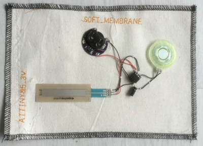

intermediate result, without an embroidered title.
Woven battery holder - ATtiny connected within the woven structure
Made on a so called baby loom, see last image if this section.
A simple circuit with an ATtiny85, and two LED's. You have to fold the side so that it forms a battery holder. The LED's will blink and if you come close to the ATtiny with your finger the blinking frequency will change - capacitive effect.
You have to press the battery on to the yarn.
The polarity - plus and minus are indicated on the swatch. Don't put the battery in the wrong way: the ATtiny85 will die!


https://www.flickr.com/photos/contrechoc/albums/72157713148275338
https://github.com/contrechoc/swatches/blob/master/woven_batteryholder
Weaving this swatch is time consuming! Although this is fun making, I don't think this will become very popular :-)
If you start making this: program the ATtiny85 first, before soldering the conductive wire to the legs....
You need solderable conductive wire for this: The Karl Grimm, which you cannot buy anywhere unless you are an industrial consumer!
 Another example of weaving and connecting to an ATtiny85 - which I made during the e-textile summer camp in ... 2015(?)
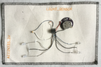
Sensor swatches
ATtiny85 + LDR light sensor.

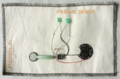
ATtiny85 + Force Sensitive sensor: https://www.floris.cc/shop/en/flex-force/738-force-sensitive-resistor.html

ATtiny85 + NTC Temperature Sensor: http://interactionstation.wdka.hro.nl/wiki/Thermistor
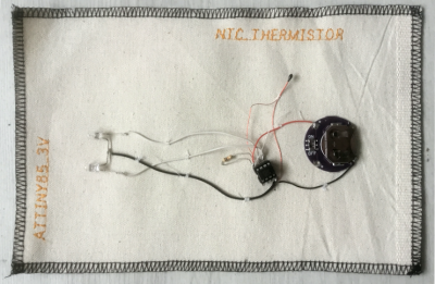

These swatches show in a simple way the working of these basic sensors.
In principle these resistors are voltage dividers, where the sensor is a variable resistance.
The data are thus "relative" to the values of the resistors, the data are not "real", not calibrated by the sensor. The data can be calibrated by the code, like the NTC.
Microcontroller ATtiny85
https://cdn.sparkfun.com/assets/2/8/b/a/a/Tiny_QuickRef_v2_2.pdf
I am using this cheap microcontroller for many smaller projects. It is very cheap compared to the Arduino, but of course, just a few PINs and just a bit of memory.
Tutorial: https://learn.sparkfun.com/tutorials/tiny-avr-programmer-hookup-guide/attiny85-use-hints
You need a chip holder, unless you want to solder directly to the pins.
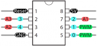
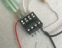
Pin view, chip holder, ATtiny85


The ATtiny is programmable inside the Arduino environment. But if you need all the memory, you can better program it in AVR.
Flashing the program is done with a programmer, the most convenient for the ATtiny85 (I think) is: Tiny AVR programmer - https://www.floris.cc/shop/en/home/996-tiny-avr-programmer.html
 Comparing the sizes of Arduino, the Arduino Pro mini, and the ATtiny85

Adafruit has boards with ATtiny, then it is easier to program and attach to the PIN's: Adafruit Trinket - for us in Europe, buy at a local webshop...
Slow and fast sensors
This swatch has a TFT screen, not sheltered in fabric.
The distinction between slow and fast sensors is not about the sensors devices, but about the data the are measuring. Temperature of air is not changing too fast, likewise air pressure, compared to data from acceleration sensors. So environmental data are changing "slow" relative to movement data. This means for programming that acceleration and movement data should be measured much more frequent than environmental data. Acceleration data should be recorded as fast as possible, while the environmental data should not "clog" this loop too much.
Fast acceleration Sensor: ADXL345: https://learn.sparkfun.com/tutorials/adxl345-hookup-guide?_ga=2.89251487.561194753.1589359662-1975814699.1588796476
Slow environmental Sensor: BME680: https://learn.adafruit.com/adafruit-bme680-humidity-temperature-barometic-pressure-voc-gas/
The code: https://github.com/contrechoc/swatches/blob/master/fast_slow_sensor_swatch
The slow data are displayed as numbers, the fast data, acceleration as graphs in time.

The sensors are providing "real" data in physical units, temperature in degrees, pressure in bar, etcetera.
These two sensors are connected using the I2C protocol.
Sparkfun and Adafruit are also providing the libraries and example code.
The sensors are connected to a Arduino Pro Mini 3V (Be careful: the 5V connection is deferred to the RAW Voltage input on the microcontroller. Then this voltage is regulated to 3.3V.

This swatch can be powered and programmed with the FTDI USB NAAR SERIEEL TTL KABEL (5V TTL) (for example: https://www.antratek.nl/ftdi-usb-naar-serieel-ttl-kabel-5v-ttl)
Be careful: This cable can also be bought for 3V - but it still delivers 5V! This could damage your 3V sensors. For this swatch, the 5V is fed into the voltage delimiter on the Pro Mini board, so that the board is running at 3V.
Soft Button TFT Lipo Pro Mini
This swatch has a soft Button to control the pictures shown on a TFT screen.
The pictures are read from an SD card.
The TFT screen is connected to a Pro Mini microcontroller. The TFT screen is inside a fabric holder.
The soft Button gives the input signal to the microcontroller.
On this swatch a lipo is included to power the screen and the microcontroller. To charge the lipo, there is a lipo charger added.
This swatch is running at the voltage delivered by the lipo (3.7V - 4.2V). If you want to add sensors, be careful if these sensors are running at 3V max - then you need a voltage limiter.
A switch is used to turn the microcontroller on.
Fitting all the components on the swatch is quite a job!

This swatch can be programmed with the FTDI USB NAAR SERIEEL TTL KABEL (5V TTL) (for example: https://www.antratek.nl/ftdi-usb-naar-serieel-ttl-kabel-5v-ttl)
The script is fairly basic from the example, only added a serie of images, which change if you push the soft button: https://github.com/contrechoc/swatches/blob/master/tft_screen_soft_button
References
A movie of "the" e-textile swatch book 2013: https://www.youtube.com/watch?v=YcmxE24VdWA
Documentation of the e-textile swatch exchange books:
http://etextile-summercamp.org/swatch-exchange/category/2017/
http://etextile-summercamp.org/swatch-exchange/category/2016/
http://etextile-summercamp.org/swatch-exchange/category/2015/
http://etextile-summercamp.org/swatch-exchange/category/2014/
http://etextile-summercamp.org/swatch-exchange/category/2013/
Mika and Hannah: https://www.kobakant.at/DIY/
Many techniques and workshops are documented here:
http://etextile-summercamp.org/2016/
http://etextile-summercamp.org/2015/