Difference between revisions of "BASIC ELECTRONICS - Useful and fun info"
| (5 intermediate revisions by the same user not shown) | |||
| Line 158: | Line 158: | ||
<br> | <br> | ||
There are switches that have three or four or more poles. But this is enough for a start:) | There are switches that have three or four or more poles. But this is enough for a start:) | ||
| + | <br> | ||
| + | <br> | ||
| + | '''BUTTONS''' | ||
| + | <br> | ||
| + | <br> | ||
| + | Soo...... what about the buttons...they are also switches | ||
| + | <br> | ||
| + | like this one | ||
| + | <br> | ||
| + | [[File:Pushbutton.png| left]] | ||
| + | <br> | ||
| + | <br> | ||
| + | <br>They also come in many different flavors and colors, but they also interfere with the circuit, in most cases only while the button is pressed. | ||
| + | Like you computer keyboard buttons, when the key is pressed, something is happening, and when you let go, it stops. | ||
| + | <br> | ||
| + | <br> | ||
| + | <br> | ||
| + | <br> | ||
| + | A PUSHBUTTON is called a '''momentary switch''', because it makes only a momentary contact. Any spring-loaded switch or button that wants to jump back to its original position is known as a momentary switch. | ||
| + | <br> | ||
| + | momentary switches can be '''NORMALLY''' OPEN (NO), meaning a that such a switch makes contact only when you push it, and flips back to make no contact when you let it go. | ||
| + | <br> | ||
| + | <br> | ||
| + | while a '''NORMALLY CLOSED''' (NC) button works the opposite way, it is normally ON, but when you push it, you break the connection. So, the OFF state is momentary. | ||
| + | <br> | ||
| + | <br> | ||
| + | that's how the symbols look like | ||
| + | <br> | ||
| + | <br> | ||
| + | [[File:Pushbuttonschematic.png]] | ||
| + | <br> | ||
| + | <br> | ||
| + | <br> | ||
| + | ===RESISTORS=== | ||
| + | |||
| + | Resistors are the most beautiful components, small, delicate and colorful.<br> | ||
| + | All they do is RESIST CURRENT!<br> | ||
| + | [[File:Resitor.png]] | ||
| + | <br> | ||
| + | <br> | ||
| + | The Resistance of a resistor is measured in Ohm (Ω), so guess.........you can use OHM'S LAW !<br> | ||
| + | '''A * Ω = V''' or '''V / Ω = A''' | ||
| + | <br> | ||
| + | When 1mA flows through a 3.3kΩ resistor, there will be 3.3V across it. With 6V across a 120Ω resistor, a 50mA current will flow through it. | ||
| + | <br> | ||
| + | <br> | ||
| + | The resistance of the resistors ( or how many Ohms each resistor is) can be found by decoding the color stripes on it. And HAPPILY, there are a lot of online calculators that help you do this fast. [[http://www.hobby-hour.com/electronics/resistorcalculator.php| for example THIS one]] | ||
| + | <br> | ||
| + | These resistors have a FIXED resistance, | ||
| + | <br> | ||
| + | but there are also '''VARIABLE RESISTORS''' a.k.a. '''POTENTIOMETERS''' | ||
| + | <br> | ||
| + | [[File:Pot.png|right]]<br> | ||
| + | <br> | ||
| + | <br> | ||
| + | <br> | ||
| + | It is a resistor which resistance can be changed, by turning a knob. They can also look different, but commonly look like this | ||
| + | <br> | ||
| + | <br> | ||
| + | and the symbols for the resistors and pots | ||
| + | <br> | ||
| + | [[File:Resitorshematic.png]] | ||
| + | |||
| + | |||
| + | ===CAPACITORS=== | ||
| + | <br> | ||
| + | In ultra short - Capacitors are storage vessels for electric charge. <br> A capacitor stores energy - and then later releases it. | ||
| + | <br> | ||
| + | The Capacitance of a capacitor dictates how much energy can be stored, and is measured in Farad (F). | ||
| + | A steady current of 1mA will make the voltage across a 1μF capacitor rise with 1V per msec (= 1kV / sec). | ||
| + | <br> | ||
| + | <br> | ||
| + | Capacitors can be <br> | ||
| + | '''CERAMIC''' - have no polarity (can be different colors and shapes)<br> | ||
| + | '''ELECTROLYTIC''' - have a positive and negative leg ( the negative is marked by a stripe on the body of the capacitor) and its is important how you connect them, just like Leds.<br> | ||
| + | there are also VARIABLE capacitors - but lets leave them for now | ||
| + | |||
| + | <br> | ||
| + | [[File:Capacitors.png | 800 px]] | ||
== Schematics == | == Schematics == | ||
== Prototyping a circuit == | == Prototyping a circuit == | ||
| + | |||
| + | |||
| + | a very simple touch circuit | ||
| + | |||
| + | |||
| + | [[File:Touchswitch.png | 500 px]] | ||
| + | <br> | ||
| + | <br> | ||
| + | <br> | ||
| + | Do not forget to add a resistor to the led according to your battery | ||
== Resources, tutorials and all kinds of useful online places == | == Resources, tutorials and all kinds of useful online places == | ||
| + | |||
| + | |||
| + | [[Category:OpenAanbod]] | ||
Revision as of 16:21, 15 June 2015
THIS PAGE IS IN PROGRESS .....loading
Basic Electronics
Hello, here you can find knowledge that will be useful in order to start working with electronics! The following writings are suitable for artists and designers and such, I hope:)
What is Electricity?
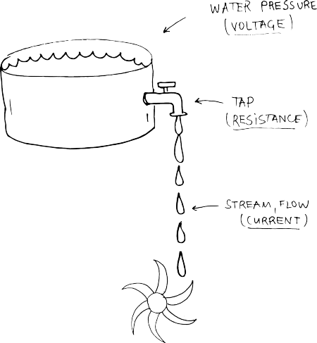
Electricity seems to be both familiar and yet abstract. Its quite hard to imagine. In order imagine electricity, there an analogy with water is often used.
Electricity is an essential ingredient of matter. Sounds poetic, doesn't it? So to picture it, lets zoom deep in and look at the smallest component of every element - 
Atoms are made of even smaller particles called protons, neutrons, and electrons. The protons and neutrons are packed tightly together in the middle of the atom, and we call them the nucleus of the atom. The electrons orbit around the nucleus. Protons and electrons have electrical charges. Protons have a positive charge, and electrons have a negative charge (neutrons don't have any charge). Normally an atom has equal numbers of protons and electrons, so they cancel each other and the atom has no electrical charge.
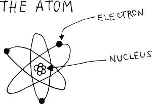
Sometimes an electron does escape from its atom and runs off to join another atom.
Atoms with escaped electrons is positively charged and respectively, if electrons jump into atoms and become more, then the atom is negatively charged.
Free atoms can move freely (almost with the speed of light) trough metals, gases and vacuum. Or they can rest.
The surface that electrons are resting is said to have negative static electrical charge. If atoms are missing some electrons then it is said to be positive static electrical charge.
Current, Voltage, Power, Resistance
So anytime electrons move, we have current! Electrons can travel trough some materials but not trough others. The ones that allow electrons to flow are called Conductors (silver, gold, iron, copper..etc.) and the ones that do not really allow the free flow of electrons are called Insulators ( wood, plastic, rubber..etc.)
Electrical current can flow in either of two directions in a conductor. If it flows only in one direction, then it is called DC ( Directional Current). We will work with it and so the following information concerns DC.
CURRENT (I) - is the quantity of electrons passing at a given point. The unit is the AMPERE, shortly called AMP. If we compare it with water, think of it as the flow of water, the stream coming from the tap.
VOLTAGE (V or E) - is electrical pressure or force. If we now compare it with water, then Voltage is the water pressure.
The higher the pressure, the higher the flow and vice versa.
POWER (P) - is the work performed by an electrical current. It is measured in WATT. The power of a DC current is its voltage(V), times its current(I).
RESISTANCE (R) - is the conductor's (material’s) tendency to resist the current. Some materials allow more current to flow and others not. Going back to water, resistance is how much the tap is open. It is measured in OHMS (Ω).
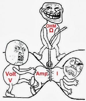
OHM's LAW
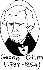
Mr. Georg Simon Ohm, a German physicist and mathematician, discovered, that there is an interrelation between Voltage, Current and Resistance.
Thus given any two of them, one can find the third one.
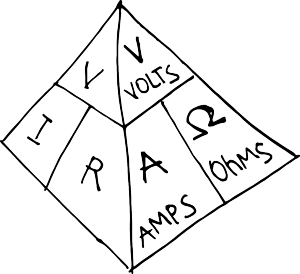
V = IxR
I = V/R
R= V/I
Here is a pyramid that shows it visually.
And shows also the actuial relationship between volts, amps and ohms, which you will see way more often than V, I and R
And here another way we can see it:)
Electronic Circuits
Measure it
Electronic Components
The BATTERY
is a source of electricity, that happens due to a chemical reaction.
There are many flavors of batteries. Different voltages, chemicals, sizes...
- There are also non-chemical batteries, for example solar batteries, they are an example of physical batteries
SWITCHES
Switches are electro-mechanical components that make or break one or more electrical contacts, thus allowing or preventing the flow of electrons ( the electric current), depending on the state of the switch. Above is its schematic symbol.
Drawn on the right, is a common switch, called a toggle switch. It connects the center terminal with the other outer terminals.
The center terminal is called the pole of the switch. Because you can flip, or throw, this switch to make two possible connections, it is called a double-throw switch. A single-pole, double-throw switch (like this one on the right) is abbreviated SPDT.
Some switches have two entirely separate poles, so you can make two separate connections simultaneously when you flip the switch. These are called double-pole switches.
here is another way to see the toggle switch above


And some examples of other types of switches
Single-pole Single-throw (makes only one connection with one pole. Its two states are simply open and closed)
and Double-pole Single-throw(makes two separate on/off connections)

There are switches that have three or four or more poles. But this is enough for a start:)
BUTTONS
Soo...... what about the buttons...they are also switches
like this one
They also come in many different flavors and colors, but they also interfere with the circuit, in most cases only while the button is pressed.
Like you computer keyboard buttons, when the key is pressed, something is happening, and when you let go, it stops.
A PUSHBUTTON is called a momentary switch, because it makes only a momentary contact. Any spring-loaded switch or button that wants to jump back to its original position is known as a momentary switch.
momentary switches can be NORMALLY OPEN (NO), meaning a that such a switch makes contact only when you push it, and flips back to make no contact when you let it go.
while a NORMALLY CLOSED (NC) button works the opposite way, it is normally ON, but when you push it, you break the connection. So, the OFF state is momentary.
that's how the symbols look like

RESISTORS
Resistors are the most beautiful components, small, delicate and colorful.
All they do is RESIST CURRENT!

The Resistance of a resistor is measured in Ohm (Ω), so guess.........you can use OHM'S LAW !
A * Ω = V or V / Ω = A
When 1mA flows through a 3.3kΩ resistor, there will be 3.3V across it. With 6V across a 120Ω resistor, a 50mA current will flow through it.
The resistance of the resistors ( or how many Ohms each resistor is) can be found by decoding the color stripes on it. And HAPPILY, there are a lot of online calculators that help you do this fast. [for example THIS one]
These resistors have a FIXED resistance,
but there are also VARIABLE RESISTORS a.k.a. POTENTIOMETERS
It is a resistor which resistance can be changed, by turning a knob. They can also look different, but commonly look like this
and the symbols for the resistors and pots

CAPACITORS
In ultra short - Capacitors are storage vessels for electric charge.
A capacitor stores energy - and then later releases it.
The Capacitance of a capacitor dictates how much energy can be stored, and is measured in Farad (F).
A steady current of 1mA will make the voltage across a 1μF capacitor rise with 1V per msec (= 1kV / sec).
Capacitors can be
CERAMIC - have no polarity (can be different colors and shapes)
ELECTROLYTIC - have a positive and negative leg ( the negative is marked by a stripe on the body of the capacitor) and its is important how you connect them, just like Leds.
there are also VARIABLE capacitors - but lets leave them for now
Schematics
Prototyping a circuit
a very simple touch circuit
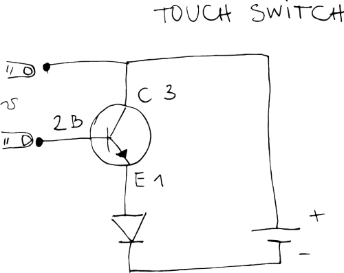
Do not forget to add a resistor to the led according to your battery
