Energy Harvesting Transformation Design
Renewables, harvesting, basics
Climate
Electricity is one of most efficient energy carriers and has become an important driver for modern human lifestyle. Electricity can be used directly with very high efficiency[2]. According to International Energy Agency (IEA), modern economies depend on reliable and affordable delivery of electricity . Access to modern energy such as electricity is an important aspect of human development; there is a positive correlation between electricity consumption per capita (in kWh) and human development index (HDI) and also gross domestic product(GDP) from 120 countries. Electricity can be generated both from fossil fuels (coal, oil, and gas) and renewable energy sources . Renewable energy includes all energy sources that are continually replenished by nature and derived directly from the sun (e.g. thermal, photo-chemical, and photo-electric), indirectly from the sun (e.g. wind, hydropower, and photosynthetic energy stored in biomass), or from other natural phenomena (e.g. geothermal nuclear heat from earth core and tidal energy (moon)). Current world electricity generation is still dominated by fossil fuel sources (~70% of total generation). These conventional energy sources (based on oil, coal, and natural gas) have successfully driven modern economic progress. However, the excessive fossil fuel consumption causes negative impact on the environment, increased health risk and global climate change. A life cycle assessment on emissions has shown that CO2 emission per generated power (kWh) is higher in the conventional systems of electricity generation (i.e. 975.3 g-CO2/kWh for coal, 742.1 g-CO2/kWh for Oil, and 607.6 g-CO2/kWh for gas) compared to the one of renewable systems (i.e. 9.7-123.7 g-CO2/kWh for Wind, 53.4-250 for solar PV, 35-178 g-CO2/kWh for biomass, 13.6-202 for solar thermal, and 3.7-237 gCO2/kWh for hydro). Therefore, it is important to shift from conventional energy sources to lowcarbon renewable electricity sources .
The world electrification is not equally distributed. While people in developed countries are enjoying electricity for their modern life style, hundreds of millions of people in rural areas in developing countries do not have access to electricity. According to International Energy Agency, an estimated 1.1 billion people (14% of the global population) do not have access to electricity. About 84% of those without electricity access live in rural areas and more than 95% of those living without electricity are in developing countries in sub-Saharan Africa and Asia.
text fragments from 'Plant Microbial Fuel Cell in Paddy Field: a power source for rural area' by Emilius Sudirjo
Access
Fossil fuels are exhausted in only a fraction of the time needed to create them and can therefore not be considered renewable. Wind power, solar power and hydropower are usually regarded as renewable because they make use of energy sources that are renewed and therefore won’t be depleted.
It should be critically reviewed whether the overall energy balance of renewable energy technology is positive. If more energy has to be put in the technology to construct it than is generated with it, energy balance is negative and the technology cannot be considered renewable. We use the concept of payback time (PBT) to assess the renewability of the P-MFC. When energy input needed for construction of the technology can be paid back by electricity generation of the same technology within the lifetime of the materials, the technology can be considered renewable. It has long been under debate whether energy input for solar panels and wind power was actually renewable due to their long PBT. Nowadays, lifetime of both wind and solar power generally exceeds energy PBT and thus these technologies can be considered renewable.
Alternative electricity generation technologies are sometimes debated for their environmental performance, even though they are renewable. Solar panels contain scarce metals and windturbines need the rare earth metal neodymium for construction. Especially mining of these metals causes a lot of environmental pollution, thus the environmental performance of wind and solar power can be debated. Hydropower is generally considered environmental friendly based on the materials used, but debate is ongoing about the loss of natural areas due to submergence upstream of the dam.
a great podcast called "How to save a planet"
People, artists and designers
energy parasites parasite shelters Roosegarde
Microbial
The world's simplest circuit (small hands on project)
SIX OSCILLATORS ON A TWENTY-CENT CHIP,
GUARANTEED TO WORK
And what about no batteries?! Solar?
Breadboarding skills
OK, wait...the BREADBOARD
We will build our circuit on a “solderless prototyping board,” commonly referred to
as a breadboard. On it you can assemble and rearrange circuit designs quickly, without
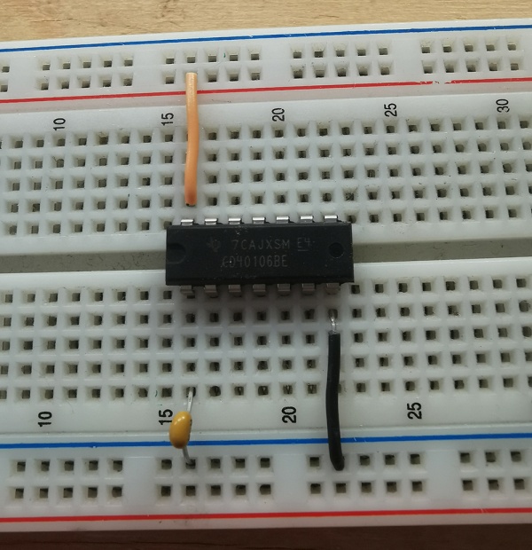
damaging components. It consists of a plastic block with lots of little holes, beneath which
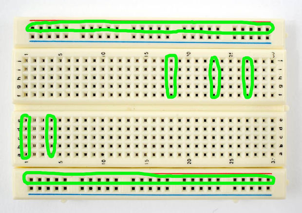
are strips of wire arranged in a matrix. Th ese strips, called “buses,” run
in one or two long horizontal strips along the top and bottom edges of the block, and in
numerous shorter vertical strips that extend above and below a central groove.
Th ere are some variation on the designs show here: some breadboards are longer, have
only one horizontal bus and the top and bottom, instead of two, or consist of multiple
modules on a metal plate, but they all depend on the same underlying bus and matrix
system.
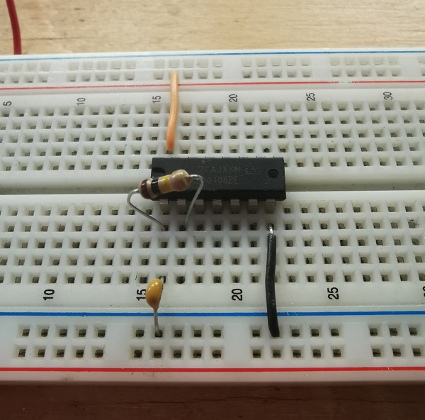
Th e holes are the right diameter for the leads of most electronic components (resistors,
capacitors, integrated circuits, etc.) and hookup wire. Circuits are built up by inserting
components into the holes on the board and connecting them by linking rows and columns
of the matrix with short strips of wire.
OK, first, what's with the name....bread board? Bread, like in food?
Well yes, kind of.
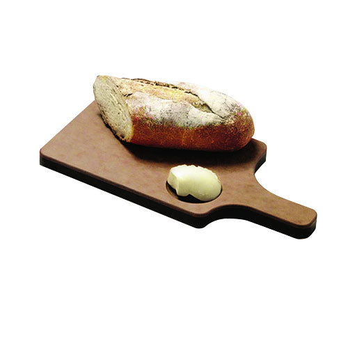
This terminology goes way back in the days.
Generally, you would mount electronic components to a piece of wood (the actual "breadboard"), and do all the wiring with point-point wire and the components just hanging between the various devices.
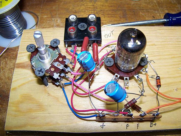
The story goes that an engineer had an idea for a vacuum tube device late one night. Looking around the house, the only base for his prototype that he found was indeed his wife's breadboard, from the breadbox.
A video by the Make magazine people
how to use the breadboard in short
Ok, but why do we need to breadboard?
Well, they are useful for making temporary circuits and prototyping, and they require absolutely no soldering.
Prototyping is the process of testing out an idea by creating a preliminary model from which other forms are developed or copied, and it is one of the most common uses for breadboards.
The best way to explain how a breadboard works is to take it apart and see what’s inside.
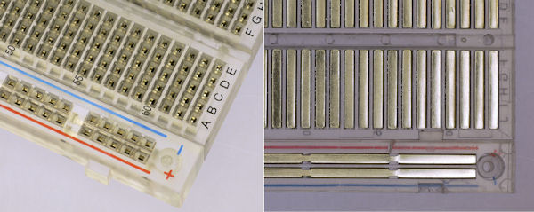
connections lines are connected like this
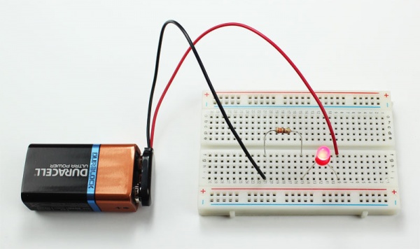
Just a LED
your first circuit
First beeps
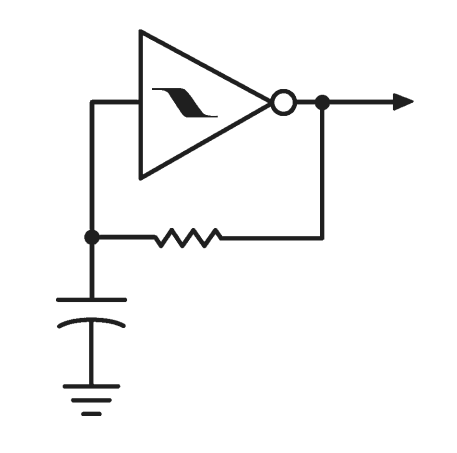
This is as good a time as any to start getting familiar with schematic representation, which conveys a circuit design independently of the physical arrangement of its components on a breadboard.
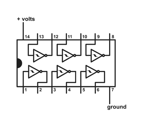
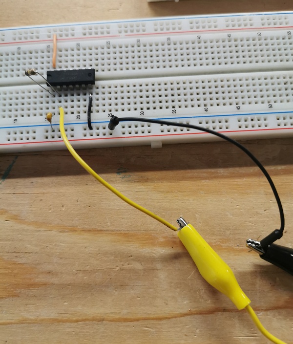
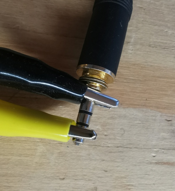
The big triangle represents one Inverter—any of the six in the IC package; the flat left side is the input, which could be pin 1, 3, 5, etc., while the pointed right side is the output (2, 4, 6, etc.) The zigzag line is the resistor, between input and output. The two vaguely parallel lines (one straight, one curved) symbolize the capacitor, connected between the Inverter’s input and the ground bus. Ground is represented by the weird runic arrangement of three lines. The signal output appears as a single line with an arrow head at the end. This is the signal that would go to the tip of a plug; the ground half of the connection is implied, rather than drawn in . Likewise the power connections to the chip ((+) to pin 14, ground (-) to pin 7) are implicit.
Variations
some thoughts on resistance
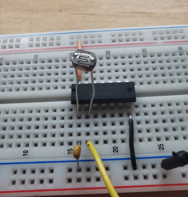
Using an LDR
using a thermistor?
Fingers?
Understanding the inverter
This circuit oscillates because of the principle of argumentation. Each Inverter stage, represented by the small triangle in the schematic, puts out the opposite of whatever signal appears at the input: if a binary “1,” represented by 9 volts, is applied to the input, then a “0” (0 volts) is sent to the output. That 0 flows through the resistor back to the input. When the 0 appears at the input the output goes to 1, which flows back to the input and the whole process begins again, causing the circuit to flip back and forth between two states, generating a square wave. The speed of the flip-flopping (the pitch we hear) depends on the values of the resistor and capacitor, the smaller the values the higher the pitch. It’s like the Monty Python argument sketch, or a dispute in a bar: I disagree with everything you say, so our output keeps flipping between yes and no according to how fast each of us can reply. Th e resistor and capacitor act like booze—the more you add the slower the argument goes, ergo the lower the pitch. Having brushed you off earlier, I will now confide that the Schmitt Trigger part of the Inverter prevents indecisiveness in the argument: the inverter snaps completely from one state to the other, from 0 to 1 and back, and never vacillates in between.
Polyphony
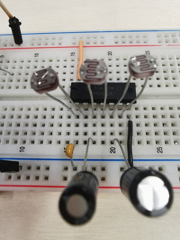
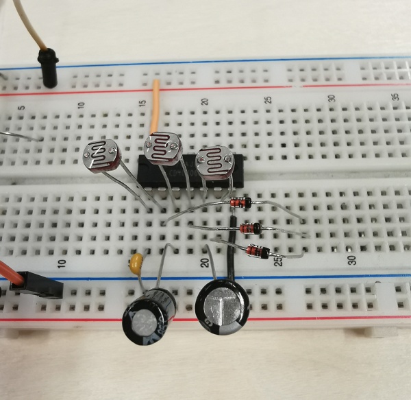
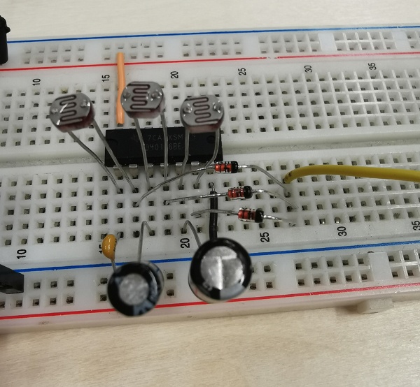
As you might be able to intuit from the schematic or any dormant knowledge of Greek, the Hex Inverter has six identical sections. You can make an additional oscillator with any of these sections, just duplicate the connections we made for our first oscillator with another set of components, attached to another set of pins: capacitor between any input and ground; resistor, pot, or photoresistor between that input and its appropriate output; connect the output via a jack to the amplifier.
