Second Steps
Summarising it
Microcontrolling it
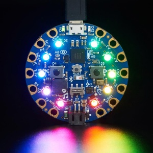
Adafruit Circuit Playground
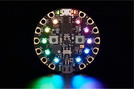
The Circuit Playground Express & Blue Fruit, produced by Adafruit, are microcontrollers, just like the Arduino Uno, but designed for wearable projects.
Thus, is a little different from the normal boards from the hardware side, since the pins go out to those big wide sewable pads, instead of normal pin headers (like on the Uno)
because Circuit Playground Express running on a faster processor compared to Arduino Uno. We can also use it for audio-based projects.
Set Up Arduino IDE
The Arduino Integrated Development Environment (IDE) is a cross-platform application (for Windows, macOS, Linux) that is written in functions from C and C++.[3] It is used to write and upload programs to Arduino compatible boards, but also, with the help of third-party cores, other vendor development boards including circuit playground express.
Download and install Arduino IDE:
https://www.arduino.cc/en/software
And follow the step here:
https://learn.adafruit.com/adafruit-circuit-playground-express/set-up-arduino-ide
we need 3 steps to set up Arduino IDE for circuit playground express.
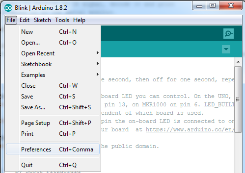
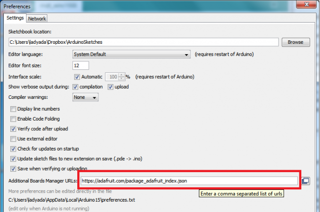
1. First activate the Adafruit URL
go to File --> preferences
copy the link below to Additional Boards Manager URLs:
https://adafruit.github.io/arduino-board-index/package_adafruit_index.json
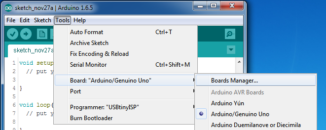
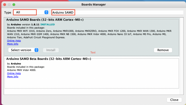
2. Then install the Adafruit SAMD package
open the Boards Manager by navigating to the Tools->Board menu.
You can type Arduino SAMD in the top search bar, then when you see the entry, click Install
3. install Circuit Playground Library.
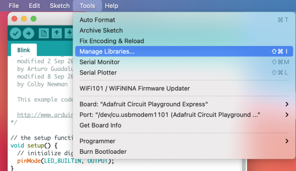
Go to Tools --> Manage Libraries.
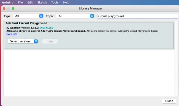
Type Circuit Playground in the top search bar then install circuit playground Library.
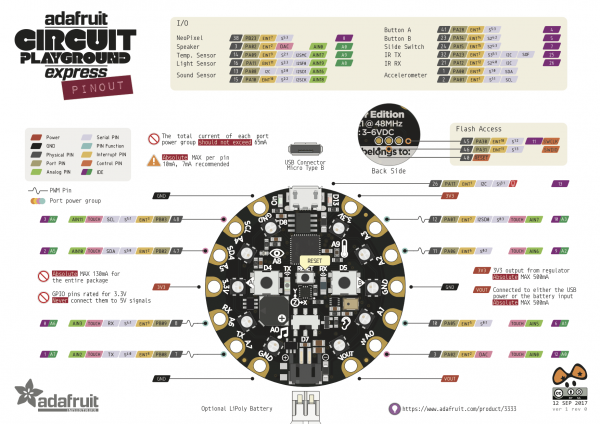
CPX onboard sensors & Pinouts
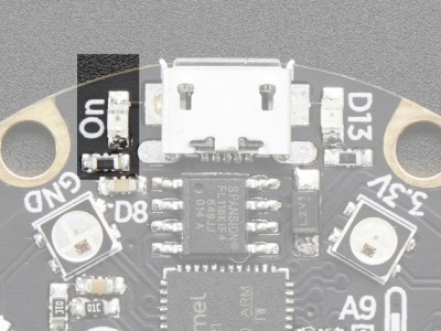
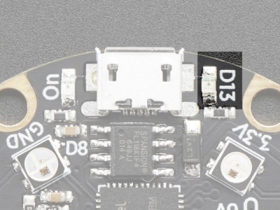
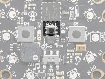
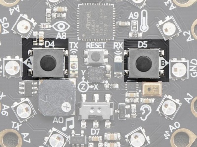
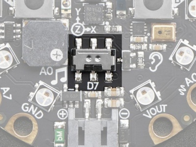
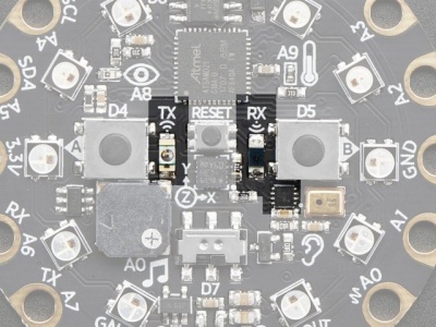
1. Green LED lets you know that the CPX is powered on.------ 2. Red LED on Digital pin#13
3. This small button is for Resetting the board. ------------------ 4. Button A and B on Digital pin #4 and #5
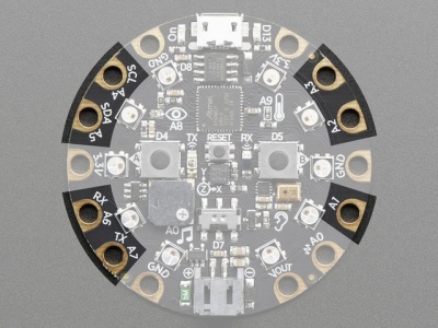
5. slide switch on Digital pin #7 - - - - - - - - - - - - - - - - - - - - - - 6. 7 Capacitive Touch pads from A1-A7
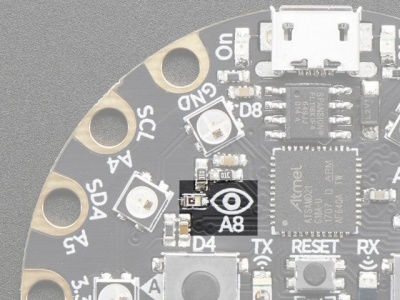
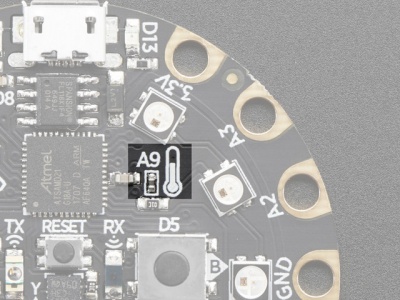
7. Light Sensor on pin A8 - - - - - - - - - - - - - - - - - - - - - - - - - - - 8. Temperature Sensor on A9
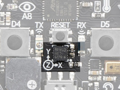
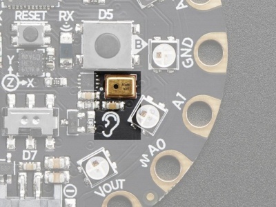
9. motion sensor (LIS3DH xyz) - - - - - - - - - - - - - - - - - - - - - - - - - 10. Microphone Audio Sensor
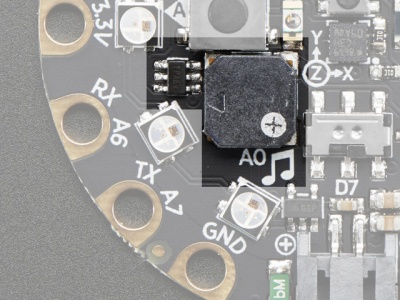
11. speaker and audio output pin on A0
12. Infrared Receive/Transmit
Pinouts:
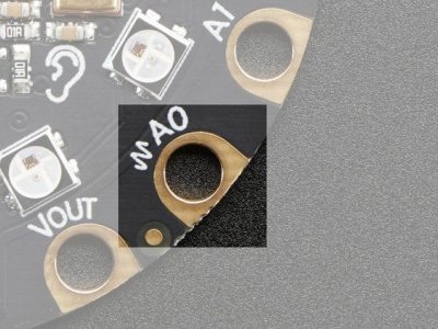
A0 / D12 - true analog output so it's great for playing audio clips.
A1 / D6 - digital I/O, or analog Input, PWM output,capacitive touch sensor
A2 / D9 - digital I/O, or analog Input, PWM output,capacitive touch sensor
A3 / D10 - digital I/O, or analog Input.PWM output,capacitive touch sensor
A4 / D3 - digital I/O, or analog Input, capacitive touch sensor
A5 / D2 - digital I/O, or analog Input, capacitive touch sensor
A6 / D0 - digital I/O, or analog Input, PWM output,capacitive touch sensor
A7 / D1 - digital I/O, or analog Input, PWM output,capacitive touch sensor
Examples
Compile Upload and Blink
let's Open Arduino IDE and open the Blink example.
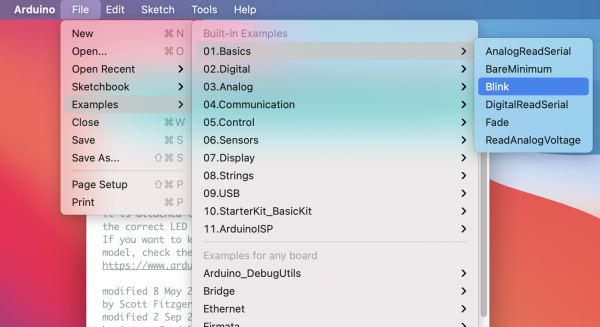
GO TO File--> Examples -->01.Basics --> Blink this will open example Blink.
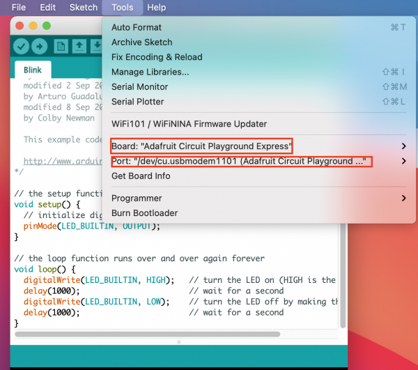
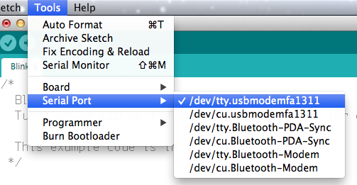
Select Board and Port :
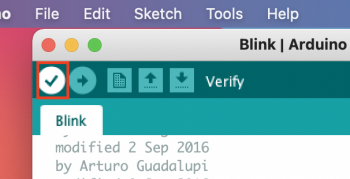
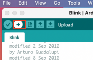
Verify and upload the code
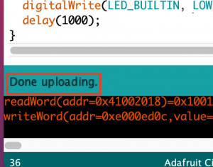
when it finished uploading you can see a message "Done uploading "at the bottom left corner:
This example turns an onboard LED on for one second, then off for one second, repeatedly. normally onboard led is on Pin 13.
in this case, is the Red LED on CPX.
NeoPixels
 1#include <Adafruit_CircuitPlayground.h>
 2
 3void setup() {
 4  CircuitPlayground.begin();
 5}
 6
 7void loop() {
 8// RGB
 9  CircuitPlayground.setPixelColor(0, 255,   0,   0);
10//Hexadecimal color code
11
12  CircuitPlayground.setPixelColor(3, 0xFF0000);
13  delay(1000);
14  CircuitPlayground.clearPixels();
15  delay(500);
16}
light up Neopixels one after another with a for loop:
"for"statement:
https://www.arduino.cc/reference/en/language/structure/control-structure/for/
 1//light up Neopixels one after another
 2#include <Adafruit_CircuitPlayground.h>
 3
 4void setup() {
 5  CircuitPlayground.begin();
 6}
 7
 8void loop() {
 9
10
11for (int i=0;i<10;i++){
12
13    CircuitPlayground.setPixelColor(i, 200,   100,   0);
14    delay(100);
15
16 }
17
18}
smiley face
 1#include <Adafruit_CircuitPlayground.h>
 2void setup() {
 3  CircuitPlayground.begin();
 4}
 5
 6void loop() {
 7
 8
 9for (int i=0;i<10;i++){
10    if (i!=0 && i!=2 && i!=4){
11    CircuitPlayground.setPixelColor(i, 255,   0,   0);
12    delay(100);
13     }
14      }
15
16delay(500);
17
18for (int i=10;i>0;i--){
19    if (i!=0 && i!=2 && i!=4){
20    CircuitPlayground.setPixelColor(i, 0,   0,   0);
21    delay(100);
22
23     }
24      }
25delay(500);
26}
"if"statement:
https://www.arduino.cc/reference/en/language/structure/control-structure/if/
"if…else":
https://www.arduino.cc/reference/en/language/structure/control-structure/else/
Buttons-DigitalRead
 1#include <Adafruit_CircuitPlayground.h>
 2
 3int leftButton;
 4int rightButton;
 5
 6void setup() {
 7  Serial.begin(9600);
 8  CircuitPlayground.begin();
 9}
10
11void loop() {
12  leftButton = CircuitPlayground.leftButton();
13  rightButton = CircuitPlayground.rightButton();
14
15   Serial.print("Left Button: ");
16   Serial.print(leftButton);
17   Serial.print("   Right Button: ");
18   Serial.print(rightButton);
19   Serial.println();
20   delay(30);
21}
 1#include <Adafruit_CircuitPlayground.h>
 2
 3int leftButton;
 4int rightButton;
 5
 6void setup() {
 7  Serial.begin(9600);
 8  CircuitPlayground.begin();
 9}
10
11void loop() {
12  leftButton = CircuitPlayground.leftButton();
13  rightButton = CircuitPlayground.rightButton();
14  if (leftButton==1) {
15    for (int i=0;i<10;i++){
16      if(i!=0 && i!=2 && i!=4){
17        CircuitPlayground.setPixelColor(i, 200,   100,   0);
18        delay(100);}
19     }
20   }
21
22  if (rightButton==1) {
23    CircuitPlayground.clearPixels();
24   }
25   Serial.print("Left Button: ");
26   Serial.print(leftButton);
27   Serial.print("   Right Button: ");
28   Serial.print(rightButton);
29   Serial.println();
30   delay(30);
31}
AnalogRead (Light Sensor and soft Pressure/Bend Sensor)
 1#include <Adafruit_CircuitPlayground.h>
 2
 3int value;
 4
 5void setup() {
 6  Serial.begin(9600);
 7  CircuitPlayground.begin();
 8}
 9
10void loop() {
11  value = CircuitPlayground.lightSensor();
12
13  Serial.print("Light Sensor: ");
14  Serial.println(value);
15
16  delay(1000);
17}
 1#include <Adafruit_CircuitPlayground.h>
 2
 3int value;
 4int toneValue;
 5void setup() {
 6  Serial.begin(9600);
 7  CircuitPlayground.begin();
 8}
 9
10void loop() {
11  value = CircuitPlayground.lightSensor();
12
13  Serial.print("Light Sensor: ");
14  Serial.println(value);
15  toneValue=value+150;
16  delay(10);
17  tone(A0, toneValue, 10);
18}
Modified to work with our sensor
 1#include <Adafruit_CircuitPlayground.h>
 2
 3int value;
 4int toneValue;
 5void setup() {
 6  Serial.begin(9600);
 7  CircuitPlayground.begin();
 8}
 9
10void loop() {
11  value = analogRead(A1);
12
13  Serial.print("Pressure Sensor: ");
14  Serial.println(value);
15  toneValue=value-150;
16  delay(10);
17  tone(A0, toneValue, 10);
18}
analog and digital
Capacitive touch sensor
 1#include <Adafruit_CircuitPlayground.h>
 2void setup() {
 3
 4  Serial.begin(9600);
 5  CircuitPlayground.begin();
 6}
 7
 8void loop() {
 9   //https://learn.adafruit.com/adafruit-circuit-playground-express/pinouts
10  // A0=D12, A1=D6, A2=D9, A3=D10, A4=D3, A5=D2, A6=D0,A7=D1
11  Serial.print(" A1: "); Serial.print(CircuitPlayground.readCap(6));
12  Serial.print(" A2: "); Serial.print(CircuitPlayground.readCap(9));
13  Serial.print(" A3: "); Serial.print(CircuitPlayground.readCap(10));
14  Serial.print(" A4: "); Serial.print(CircuitPlayground.readCap(3));
15  Serial.print(" A5: "); Serial.print(CircuitPlayground.readCap(2));
16  Serial.print(" A6: "); Serial.print(CircuitPlayground.readCap(0));
17  Serial.print(" A7: "); Serial.println(CircuitPlayground.readCap(1));
18
19  delay(50);
20
21}
 1#include <Adafruit_CircuitPlayground.h>
 2void setup() {
 3
 4  Serial.begin(9600);
 5  CircuitPlayground.begin();
 6}
 7
 8void loop() {
 9  //https://learn.adafruit.com/adafruit-circuit-playground-express/pinouts
10  // A0=D12, A1=D6, A2=D9, A3=D10, A4=D3, A5=D2, A6=D0,A7=D1
11   Serial.println("0 ");
12 if (CircuitPlayground.readCap(6)>400){
13     CircuitPlayground.setPixelColor(0, 255,   0,   0);
14     CircuitPlayground.playTone(523, 300);
15     }
16
17 if (CircuitPlayground.readCap(9)>400){
18      CircuitPlayground.setPixelColor(1, 180,   60,   0);
19       CircuitPlayground.playTone(587, 300);
20      }
21 if (CircuitPlayground.readCap(10)>400){
22      CircuitPlayground.setPixelColor(2, 100,   200,   0);
23       CircuitPlayground.playTone(659, 300);
24      }
25 if (CircuitPlayground.readCap(3)>400){
26      CircuitPlayground.setPixelColor(3, 50,   250,   50);
27       CircuitPlayground.playTone(698, 300);
28      }
29  if (CircuitPlayground.readCap(2)>400){
30      CircuitPlayground.setPixelColor(4, 0,   200,   100);
31       CircuitPlayground.playTone(784, 300);
32      }
33   if (CircuitPlayground.readCap(0)>400){
34      CircuitPlayground.setPixelColor(5, 0,   150,   150);
35       CircuitPlayground.playTone(880, 300);
36      }
37    if (CircuitPlayground.readCap(1)>400){
38      CircuitPlayground.setPixelColor(6, 255,   50,   200);
39       CircuitPlayground.playTone(988, 300);
40      }
41    delay(50);
42    CircuitPlayground.clearPixels();
43}
Sound sensor
 1#include <Adafruit_CircuitPlayground.h>
 2
 3float value;
 4
 5void setup() {
 6  Serial.begin(9600);
 7  CircuitPlayground.begin();
 8}
 9
10void loop() {
11  // Take 10 milliseconds of sound data to calculate
12  value = CircuitPlayground.mic.soundPressureLevel(10);
13
14  Serial.print("Sound Sensor SPL: ");
15  Serial.println(value);
16
17  delay(90);
18}
 1#include <Adafruit_CircuitPlayground.h>
 2
 3float value;
 4
 5void setup() {
 6  Serial.begin(9600);
 7  CircuitPlayground.begin();
 8}
 9
10void loop() {
11  // Take 10 milliseconds of sound data to calculate
12  value = CircuitPlayground.mic.soundPressureLevel(10);
13
14  Serial.print("Sound Sensor SPL: ");
15  Serial.println(value);
16  delay(50);
17
18 if(value>80){
19  for (int i=0;i<10;i++){
20    if (i!=0 && i!=2 && i!=4){
21    CircuitPlayground.setPixelColor(i, 155,   0,   150);
22    delay(100);
23    if( i==9){
24       delay(1000);
25      CircuitPlayground.clearPixels();
26      }
27    }
28  }
29
30 }
31}
Most Common Data Types:
int, float, string
integer: numbers that can be written without a fractional component such as 1 4 5 -8 -10
float: numbers with a decimal point such as 1.5 55.67
string: message inside double quotes ("Abc") "Button Value".
you can convert data types by using int(); float(); Sting();
and map() can help us to Re-maps a number from one range to another.
map(value, fromLow, fromHigh, toLow, toHigh)
https://www.arduino.cc/reference/en/language/functions/math/map/
Motion Sensor
accelerometer
 1#include <Adafruit_CircuitPlayground.h>
 2
 3float X, Y, Z;
 4
 5void setup() {
 6  Serial.begin(9600);
 7  CircuitPlayground.begin();
 8}
 9
10void loop() {
11  X = CircuitPlayground.motionX();
12  Y = CircuitPlayground.motionY();
13  Z = CircuitPlayground.motionZ();
14
15  Serial.print("X: ");
16  Serial.print(X);
17  Serial.print("  Y: ");
18  Serial.print(Y);
19  Serial.print("  Z: ");
20  Serial.println(Z);
21
22  delay(1000);
23}
 1#include <Adafruit_CircuitPlayground.h>
 2
 3float X, Y, Z;
 4int zVal;
 5
 6void setup() {
 7  Serial.begin(9600);
 8  CircuitPlayground.begin();
 9}
10
11void loop() {
12  X = CircuitPlayground.motionX();
13  Y = CircuitPlayground.motionY();
14  Z = CircuitPlayground.motionZ();
15  Serial.print("X: ");
16  Serial.print(X);
17  Serial.print("  Y: ");
18  Serial.print(Y);
19  Serial.print("  Z: ");
20  Serial.println(Z);
21  Serial.println(zVal);
22  zVal=map(Z,-20,20,100,800);
23
24 // tone(A0, zVal, 10);
25  delay(10);
26  if(X>5){
27    for (int i=0;i<5;i++){
28       CircuitPlayground.setPixelColor(i, 200,   100,   0);
29       delay(10);}
30   }else{CircuitPlayground.clearPixels();}
31
32  if(X<-5){
33    for (int i=5;i<10;i++){
34       CircuitPlayground.setPixelColor(i, 200,   100,   0);
35        delay(10);}
36   }else{CircuitPlayground.clearPixels();}
37   if(Z<1){
38    for (int i=0;i<10;i++){
39       CircuitPlayground.setPixelColor(i, 50,   100,   100);
40        delay(10);}
41   }else{CircuitPlayground.clearPixels();}
42}
CircuitPython & MU Editor
Python is the fastest-growing programming language. And CircuitPython is based on Python language but designed to run on microcontroller boards.
CircuitPython is designed with education in mind.
It's easy to start learning how to program and you get immediate feedback from the board.
Before we start we all have to do this to set up:
1. Install or update CircuitPython!
https://learn.adafruit.com/adafruit-circuit-playground-express/circuitpython-quickstart
*1. Click the link below and download the latest UF2 file:
https://circuitpython.org/board/circuitplayground_express/
*2. Plug your Circuit Playground Express into your computer via a (data)USB cable.
*3. Double-click the small Reset button in the middle of the CPX(short for circuit playground express).
 you will see all of the LEDs turn green. If they turn all red, check the USB cable, try another USB port, etc.
 (If double-clicking doesn't do it, try a single-click!)
*4. You will see a new disk drive appear called CPLAYBOOT
  Drag the adafruit-circuitpython-etc...uf2 file onto it.
*5. The CPLAYBOOT drive will disappear and a new disk drive will appear called CIRCUITPY
That's it! You're done :)
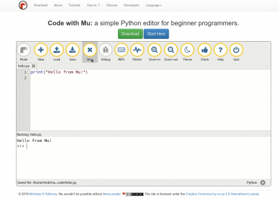
2. Installing Mu Editor
Download Mu from(if you are using computers from school, the Mu Editor is already installed)
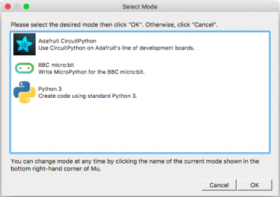
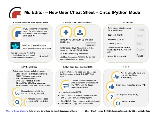
The first time you start Mu, you will be prompted to select your 'mode' -
you can always change your mind later. For now please select CircuitPython!
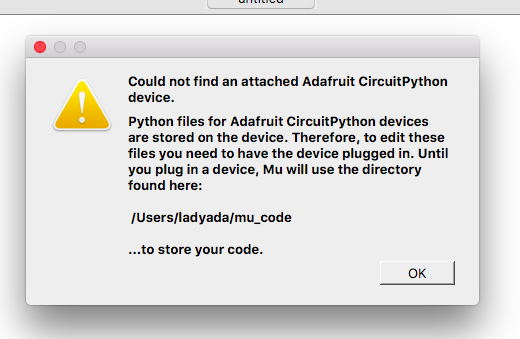
Mu attempts to auto-detect your board, so please plug in your CircuitPython device and make sure it shows up as a CIRCUITPY drive before starting Mu
3. Hello, World!
In the code area, where it says, # Write your code here :-), write the following code:
print( 8 )
Then click the Save button to save the code and run it on the CircuitPlayground.
You should see this message appear in the Serial Dialogue Panel:
code.py output: 8
Change the message to something else. If you want to print characters instead of numbers, you must use quotation marks.
print( "hello" )
Let's program the device to print two things, with a time delay in between the two print statements:
import time
print( "hello" )
time.sleep( 0.5 )
print( "World" )
Now let's make a loop, so the message will be running forever:
import time

while True:

 print( "hello" )
 time.sleep( 0.5 )
 print( "World" )
Indentation and commenting options
Python programs are Space holder Character Sensitive.
To indent the three lines, I selected them all and then pressed the Tab key.
To unindent, select some lines and press Shift-Tab. For commenting: select lines and press command(control)-k
4. Interacting to the Serial Console
The REPL
The other feature of the serial connection is the Read-Evaluate-Print-Loop, or REPL.
The REPL allows you to enter individual lines of code and have them run immediately.
It's really handy if you're running into trouble with a particular program and can't figure out why.
It's interactive so it's great for testing new ideas.
To use the REPL, you first need to be connected to the serial console.
Once that connection has been established, you'll want to press Ctrl + C.
If there is code running, it will stop and you'll see Press any key to enter the REPL. Use CTRL-D to reload.
Follow those instructions, and press any key on your keyboard.
https://learn.adafruit.com/adafruit-circuit-playground-express/the-repl
5. Simple digital and analog inputs and output
1. Digital:
https://learn.adafruit.com/circuitpython-essentials/circuitpython-digital-in-out
2. Digital in and out With external electronic components:
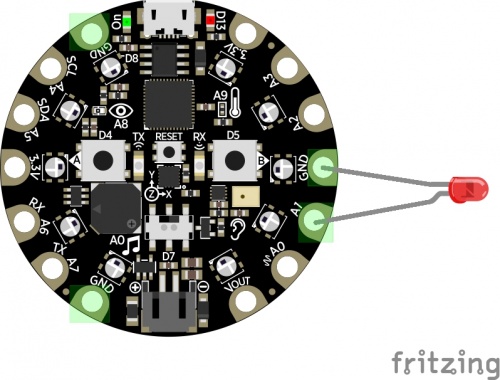
After we followed the example, now let's try to connect an external Led.
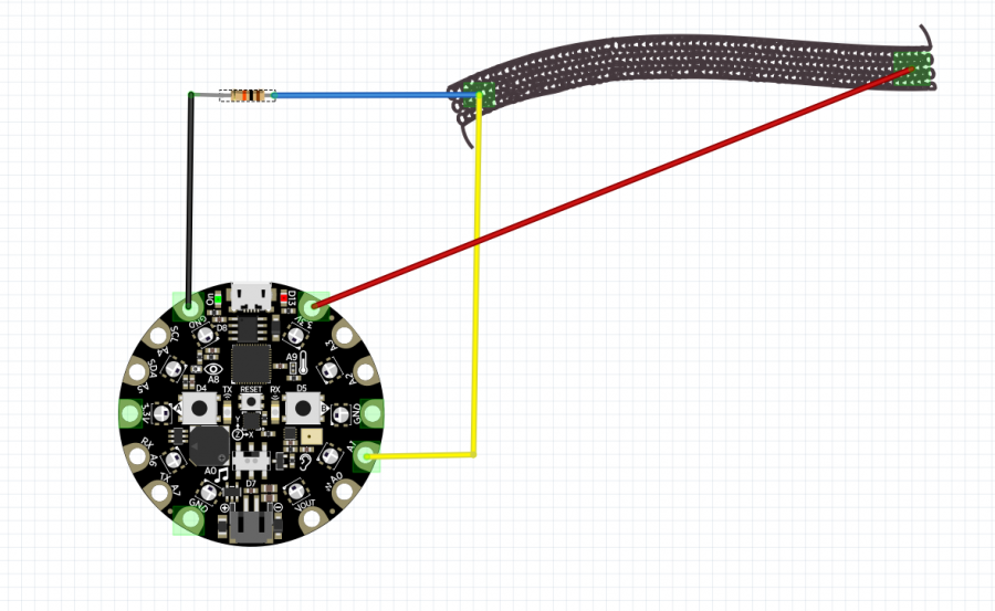
let's connect the led to A1(D6). There is a list of pinout from Adafruit's website:
https://learn.adafruit.com/adafruit-circuit-playground-express/pinouts
3. Analog input:
https://learn.adafruit.com/circuitpython-essentials/circuitpython-analog-in
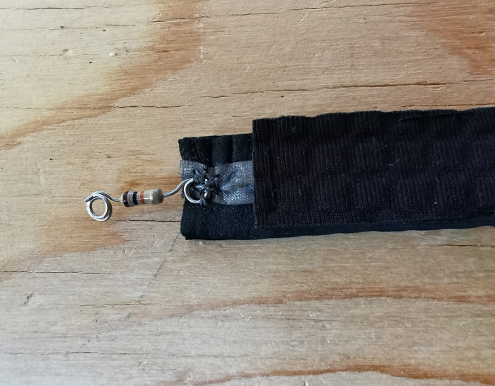
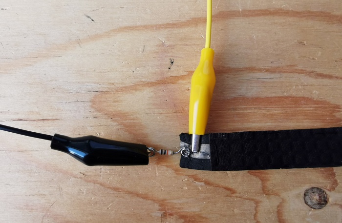
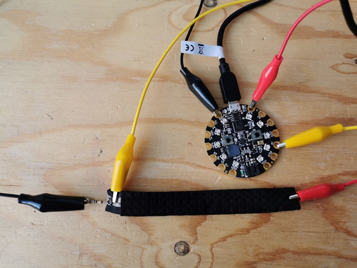
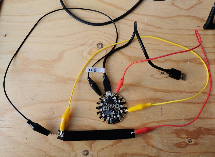
4. Analog input and output with external electronic components:
 """CircuitPython Essentials Analog In example"""
 import time
 import board
 from analogio import AnalogIn

 analog_in = AnalogIn(board.A1)

 while True:
    print(analog_in.value)
    time.sleep(0.1)
import time
import board
import analogio

from adafruit_circuitplayground import cp

analogin = analogio.AnalogIn(board.A2)

def getVoltage(pin):
    return (pin.value * 3.3) / 300

while True:
    sensor = getVoltage(analogin)
    cp.play_tone(sensor,0.05)
    print("analog voltage:", sensor)
    time.sleep(0.01)
6. CircuitPython Made Easy
Libraries:
Libraries are codes other people have written for you. The libraries we will be using are included as part of the CircuitPython code, but you still must import them into your program. Other libraries, for many uses, must be downloaded and placed in a folder named lib on the CIRCUITPY drive.
CircuitPython Libraries already included in CPX, But if you are using CPB, (CPX = Circuit Playground Express, CPB = Circuit Playground Bluefruit)
you need to install CircuitPython Libraries by download the file and put them in the folder named lib on the CIRCUITPY drive.
we will use circuit playground libraries, a simple way to include the Circuit Playground functionality in our code.
more reference and examples:
https://learn.adafruit.com/circuitpython-made-easy-on-circuit-playground-express
Examples with CPX On-Board sensors:
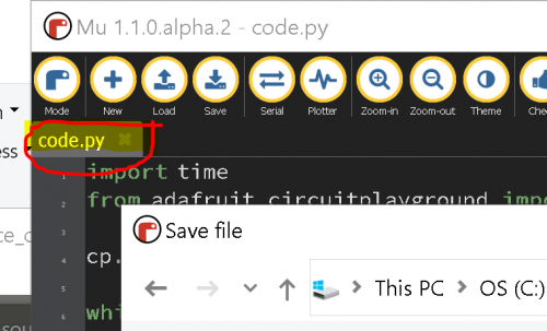
SAVE AS:
if you want to save the code.py file in different names as well as in different locations:
double click on the file name in Mu editor.
1. Red LED:
https://learn.adafruit.com/circuitpython-made-easy-on-circuit-playground-express/red-led
2. Slide Switch:
https://learn.adafruit.com/circuitpython-made-easy-on-circuit-playground-express/slide-switch
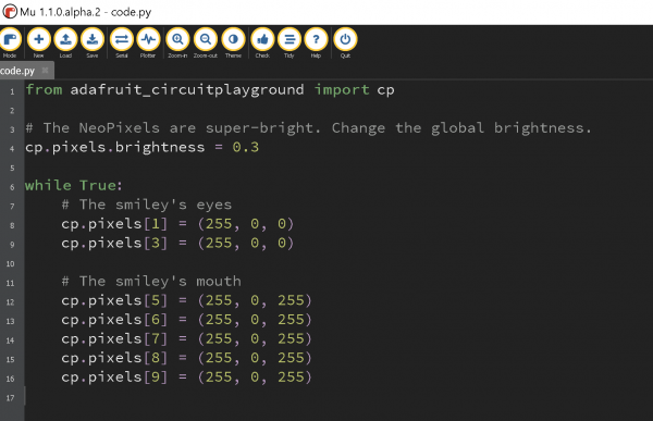
3. Smiley face
4. light sensor:
https://learn.adafruit.com/circuitpython-made-easy-on-circuit-playground-express/light
5. play tone:
https://learn.adafruit.com/circuitpython-made-easy-on-circuit-playground-express/play-tone
Exercise:
combine the code from examples "Play tone" and "light sensor". and use light sensor input to generate tones.
Conditionals:
Evaluate a condition and react. If True, do this. If False, do this other thing.

"while" creates a repeated action. while this condition is true, continue to do this thing over and over.

 when the condition is false, go on to the rest of the program.

"if" creates a single action. if this condition is true, do this thing. if false, don't do it.

"else" creates a single action, when the if the condition is false.

There is a CircuitPython reference PDF:

File:CircuitPython Reference Sheet.pdf

please read it after this lesson.
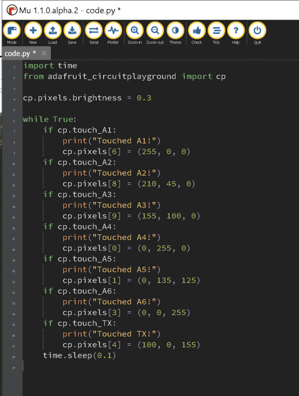
6. Capacitive Touch & NeoPixels:
7. Accelerometer: Tap
https://learn.adafruit.com/circuitpython-made-easy-on-circuit-playground-express/tap
8. Play audio file
https://learn.adafruit.com/circuitpython-made-easy-on-circuit-playground-express/play-file
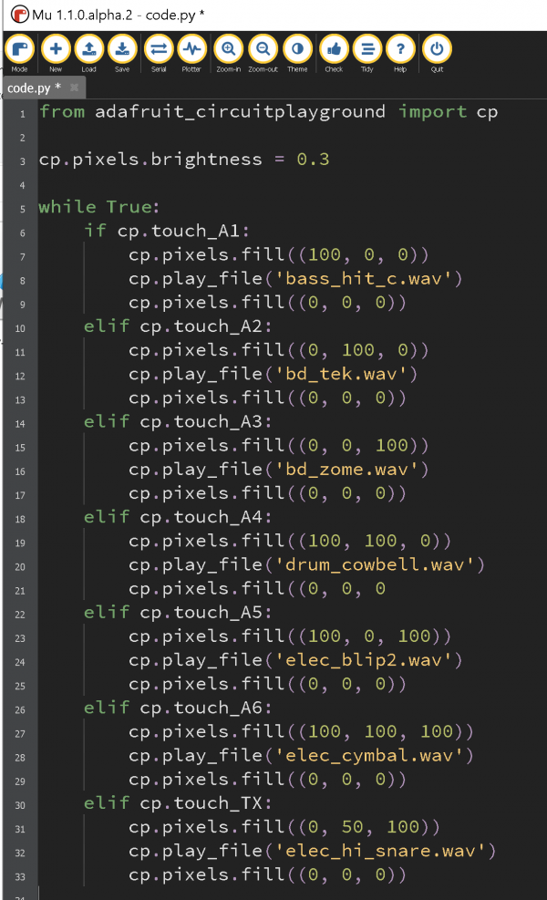
9. Drum machine
download the drum sample file here:
https://learn.adafruit.com/adafruit-circuit-playground-express/playground-drum-machine
since we are using the build-in Library, instead of using the code from the link, our code should look like this:
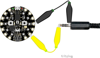
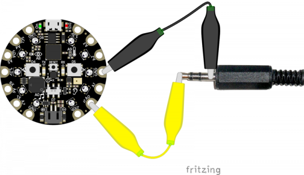
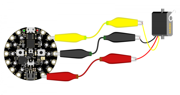
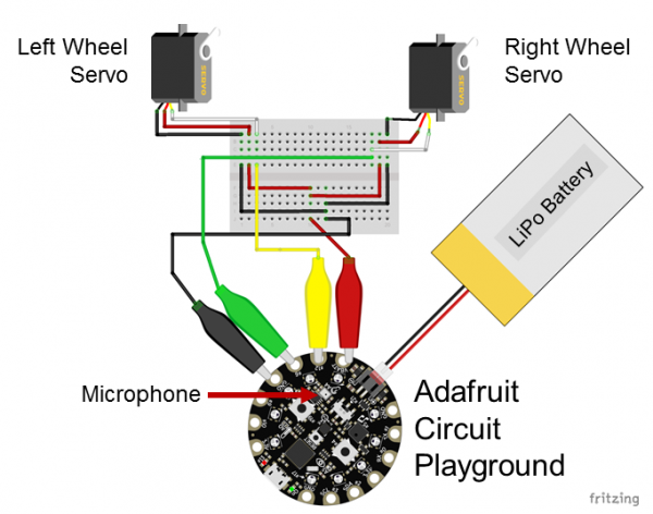
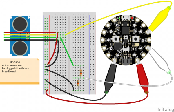
7. CPX external inputs and outputs Wiring
Connect to external speakers:
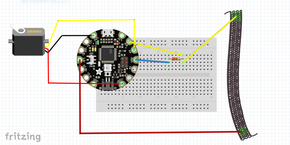
Connect to servo motors:
single motor:
multiple motors:
you can find the library and code for the servo motors here:
https://learn.adafruit.com/adafruit-circuit-playground-express/circuitpython-servo
ultra-sonic sensor:
https://learn.adafruit.com/jack-o-theremin/circuit-python-code
Arduino Uno
Overview
Hello everyone hello hello hello,
now what is an Arduino ...well...find a detailed introduction here [[1]]
Computer and processor are generic terms for the anything that can run a program, basically.
Controller or microcontroller usually refers to a simple processor that does only one task, like listening to sensors. In explaining microcontrollers, we’ll distinguish them from computers, which contain more powerful processors that can run an operating system.
Arduino is an open source physical computing platform based on a simple input/output (I/O) board and a development environment that implements the Processing language. Arduino can be used to develop standalone interactive objects
or can be connected to software on your computer.
The Arduino contains a microcontroller.
Most electronic devices today have a microcontroller at their core. Microcontrollers are optimized for control of general input and output.
What Is Physical Computing?
Physical Computing uses electronics to prototype new materials for ( in our case ) designers and artists.
Arduino is composed of two major parts: the Arduino board, which is the piece of hardware you work on when you build your objects; and the Arduino IDE, the piece of software you run on your computer. You use the IDE to create
a sketch (a little computer program) that you upload to the Arduino board. The sketch tells the board what to do.
In the meantime, HERE you can find ANYTHING about Arduino, including download the software
NOW,
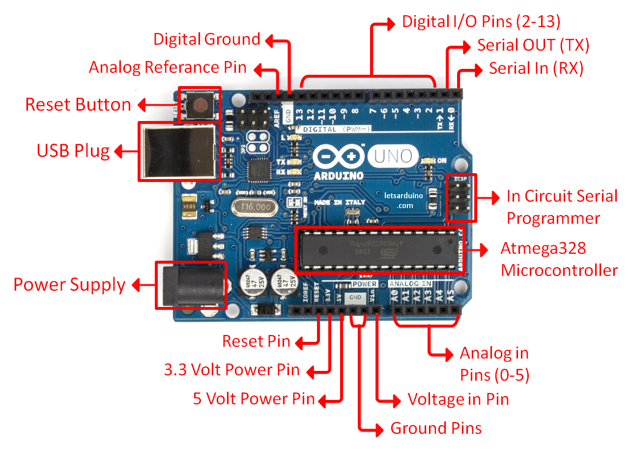
The pins on your Arduino are the places where you connect wires to construct a circuit (probably in conjunction with a breadboard and some wire. They usually have black plastic ‘headers’ that allow you to just plug a wire right into the board. The Arduino has several different kinds of pins, each of which is labeled on the board and used for different functions.
First things first, Blink it
we start by figuring put if our Arduino is all good or it is somehow damaged ...it is a basic test to check and run a simple script at the same time.
Go to File ---> Examples ---> Basics --->Blink
so we have something like this
/*
  Blink
  Turns on an LED on for one second, then off for one second, repeatedly.

  Most Arduinos have an on-board LED you can control. On the Uno and
  Leonardo, it is attached to digital pin 13. If you're unsure what
  pin the on-board LED is connected to on your Arduino model, check
  the documentation at http://www.arduino.cc

  This example code is in the public domain.

  modified 8 May 2014
  by Scott Fitzgerald
 */


// the setup function runs once when you press reset or power the board
void setup() {
  // initialize digital pin 13 as an output.
  pinMode(13, OUTPUT);
}

// the loop function runs over and over again forever
void loop() {
  digitalWrite(13, HIGH);   // turn the LED on (HIGH is the voltage level)
  delay(1000);              // wait for a second
  digitalWrite(13, LOW);    // turn the LED off by making the voltage LOW
  delay(1000);              // wait for a second
}
GOOOD! lets dissect this
- commenting / one line and multiple lines
- setup
- loop
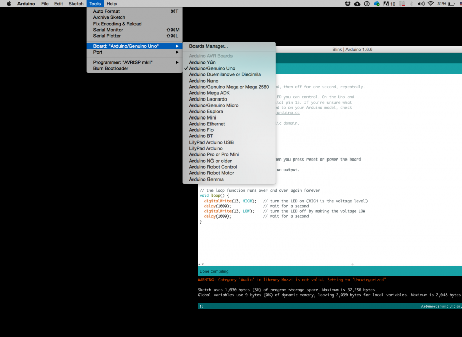
Choose board
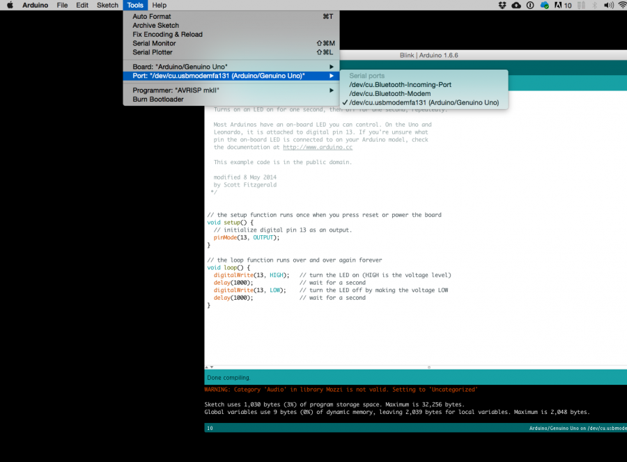
Choose port
Lets compile this
--- Press/ Click upper most left button, looks like a Tick. Observe the messages appearing in the bottom of the Arduino software window ( there must be a sentence Done Compiling
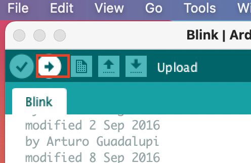
Lets upload this
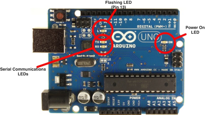
And we should have a Blinking aka Flashing on board LED
Get some data (use a pot/knob)
Sensors
Digital Sensors
Digital sensors are the sensors that gives 2 state (on/off, 5V/0V). You will connect them to digital Pins and set it as INPUT.
Digital data consists exclusively of 0s and 1s .
For example, consider a push button switch. This is one of the simplest forms of sensors. It has two discrete values. It is on, or it is off. Other 'discrete' sensors might provide you with a binary value.
Another example of a digital sensor is an accelerometer, which sends a series of data points (speed, direction, and so on) to the Arduino. Usually digital sensors need a chip in the sensor to interpret the physical data.
Analog Sensors
Analog sensors on the other hand, gives range. You connect this types of Analog sensors to Analog Input pins which is measuring the incoming voltage between 0V-5V*. Arduino converts this incoming voltage into the number between 0-1023.
Analog data is transmitted as a continuous signal, almost like a wave. In other words, an analog sensor doesn’t send a burst of 1s and 0s like digital sensors do; instead, the sensor modulates a continuous signal to transmit data.
Microcontrollers are capable of detecting binary signals: is the button pressed or not? These are digital signals. When a microcontroller is powered from five volts, it understands zero volts (0V) as a binary 0 and a five volts (5V) as a binary 1. The world however is not so simple and likes to use shades of gray. What if the signal is 2.72V? Is that a zero or a one? We often need to measure signals that vary; these are called analog signals. A 5V analog sensor may output 0.01V or 4.99V or anything inbetween. Luckily, nearly all microcontrollers have a device built into them that allows us to convert these voltages into values that we can use in a program to make a decision.
An Analog to Digital Converter (ADC) is a very useful feature that converts an analog voltage on a pin to a digital number. By converting from the analog world to the digital world, we can begin to use electronics to interface to the analog world around us.
Not every pin on a microcontroller has the ability to do analog to digital conversions. On the Arduino board, these pins have an ‘A’ in front of their label (A0 through A5) to indicate these pins can read analog voltages.
ADCs can vary greatly between microcontroller. The ADC on the Arduino is a 10-bit ADC meaning it has the ability to detect 1,024 (210) discrete analog levels. Some microcontrollers have 8-bit ADCs (28 = 256 discrete levels) and some have 16-bit ADCs (216 = 65,536 discrete levels).
OK, wait...the BREADBOARD
OK, first, what's with the name....bread board? Bread, like in food?
Well yes, kind of.
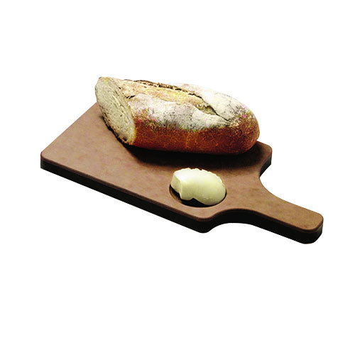
This terminology goes way back in the days.
Generally, you would mount electronic components to a piece of wood (the actual "breadboard"), and do all the wiring with point-point wire and the components just hanging between the various devices.
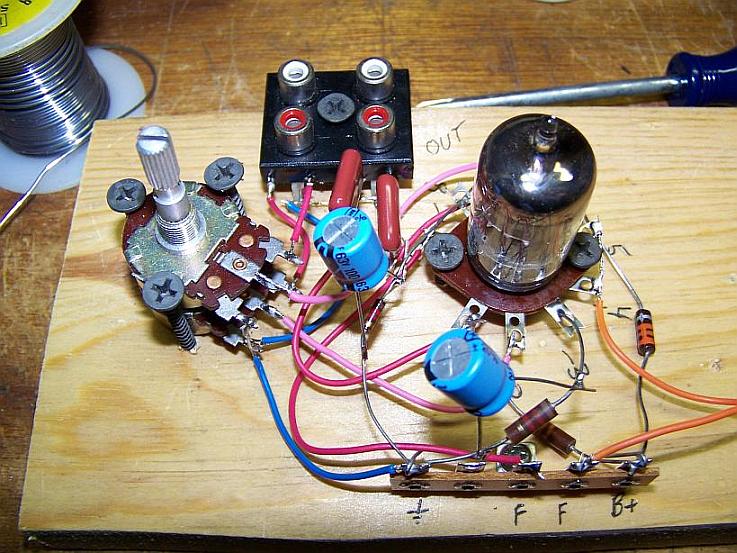
The story goes that an engineer had an idea for a vacuum tube device late one night. Looking around the house, the only base for his prototype that he found was indeed his wife's breadboard, from the breadbox.
A video by the Make magazine people
Ok, but why do we need to breadboard?
Well, they are useful for making temporary circuits and prototyping, and they require absolutely no soldering.
Prototyping is the process of testing out an idea by creating a preliminary model from which other forms are developed or copied, and it is one of the most common uses for breadboards.
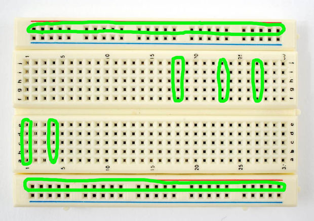
The best way to explain how a breadboard works is to take it apart and see what’s inside.
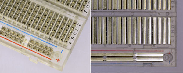
connections lines are connected like this
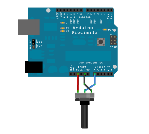
The knob
/*
  AnalogReadSerial

  Reads an analog input on pin 0, prints the result to the Serial Monitor.
  Graphical representation is available using Serial Plotter (Tools > Serial Plotter menu).
  Attach the center pin of a potentiometer to pin A0, and the outside pins to +5V and ground.

  This example code is in the public domain.

  http://www.arduino.cc/en/Tutorial/AnalogReadSerial
*/

// the setup routine runs once when you press reset:
void setup() {
  // initialize serial communication at 9600 bits per second:
  Serial.begin(9600);
}

// the loop routine runs over and over again forever:
void loop() {
  // read the input on analog pin 0:
  int sensorValue = analogRead(A0);
  // print out the value you read:
  Serial.println(sensorValue);
  delay(1);        // delay in between reads for stability
}
Adafruit Flora
How's that different?
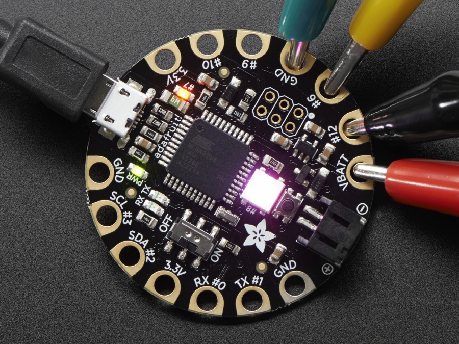
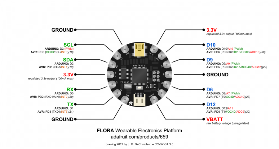
The Flora, produced by adafruit, is a microcontroller, just like the Arduino Uno, but designed for wearable projects. Thus, is a little different from the normal boards from the hardware side, since the pins go out to those big wide sewable pads, instead of normal pin headers (like on the Uno)
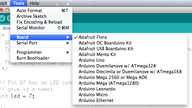
Before we start we all have to do this click click
Overview
Blink that one now
// Pin D7 has an LED connected on FLORA.
// give it a name:
int led = 7;

// the setup routine runs once when you press reset:
void setup() {
  // initialize the digital pin as an output.
  pinMode(led, OUTPUT);
}

// the loop routine runs over and over again forever:
void loop() {
  digitalWrite(led, HIGH);   // turn the LED on (HIGH is the voltage level)
  delay(1000);               // wait for a second
  digitalWrite(led, LOW);    // turn the LED off by making the voltage LOW
  delay(1000);               // wait for a second
}
Get some data
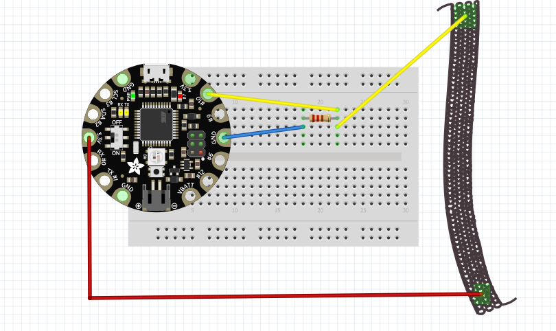
So lets see what we can get fro our sensor and the Flora
We will wire things up like that:
// any function will see this variable
const int sensor= A10;

// the setup routine runs once when you press reset:
void setup() {
  pinMode(sensor, INPUT);
  // initialize serial communication at 9600 bits per second:
  Serial.begin(9600);
}

// the loop routine runs over and over again forever:
void loop() {
  // read the input on analog pin 0:
  int sensorValue = analogRead(sensor);
  Serial.println(sensorValue);
}
Work with the data
Our motor will like values from 0 to 180 But we receive other values, so how about using the Map function
const int sensor= A10;
int mappedVal=0;


// the setup routine runs once when you press reset:
void setup() {
  pinMode(sensor, INPUT);
  // initialize serial communication at 9600 bits per second:
  Serial.begin(9600);
}

// the loop routine runs over and over again forever:
void loop() {
  // read the input on analog pin 0:
  int sensorValue = analogRead(sensor);
  mappedVal = map(sensorValue, 9, 44, 0, 180);
  Serial.println(mappedVal);
}
Still, not happy enough. We want to make sure that before we add our motor, the values do not exceed og go below the range 0-180 So let's Constrain
const int sensor= A10;
int mappedVal=0;
int constrainedVal = 0;


// the setup routine runs once when you press reset:
void setup() {
  pinMode(sensor, INPUT);
  // initialize serial communication at 9600 bits per second:
  Serial.begin(9600);
}

// the loop routine runs over and over again forever:
void loop() {
  // read the input on analog pin 0:
  int sensorValue = analogRead(sensor);
  mappedVal = map(sensorValue, 9, 44, 0, 180);
  constrainedVal = constrain(mappedVal, 10, 150);
  Serial.println(constrainedVal);
}
And finally, lets add the motor
const int sensor= A10;
const int motor = 9;
int motorval = 0;
int constrainedVal = 0;


// the setup routine runs once when you press reset:
void setup() {
  pinMode(sensor, INPUT);
  pinMode(motor, OUTPUT);
  // initialize serial communication at 9600 bits per second:
  Serial.begin(9600);
}

// the loop routine runs over and over again forever:
void loop() {
  // read the input on analog pin 0:
  int sensorValue = analogRead(sensor);
  motorval = map(sensorValue, 9, 44, 0, 180);
  constrainedVal = constrain(motorval, 10, 150);
  analogWrite( motor, constrainedVal);
  delay(1);        // delay in between reads for stability
  // print out the value you read:
  Serial.println(constrainedVal);
}
again and more links about textiles and digitals
https://xxxclairewilliamsxxx.wordpress.com/
https://www.kobakant.at/DIY/
http://etextile-summercamp.org/
http://v2.nl/search?SearchableText=textile
https://www.dezeen.com/2015/06/03/google-smartphone-interfaces-conductive-threads-clothes-textiles-project-jacquard/
http://xslabs.net/karma-chameleon/site/prototypes.php
