Difference between revisions of "Using a relay for motor control"
| (10 intermediate revisions by the same user not shown) | |||
| Line 1: | Line 1: | ||
| − | ===Using a relay for motor control== | + | ===Using a relay for motor control=== |
Relays are versatile electronic switches that can power on and off many devices. Here we will discuss a simple circuit to turn on and off your DC motor. In this example, we will use a Arduino UNO, but any microcontroller that outputs 5V on its digital pins will work. What you will need is the following: | Relays are versatile electronic switches that can power on and off many devices. Here we will discuss a simple circuit to turn on and off your DC motor. In this example, we will use a Arduino UNO, but any microcontroller that outputs 5V on its digital pins will work. What you will need is the following: | ||
| + | 1 x Computer | ||
| + | 1 x USB A to USB B cable | ||
1 x Arduino UNO (or other microcontroller) | 1 x Arduino UNO (or other microcontroller) | ||
1 x 5V relay board | 1 x 5V relay board | ||
1 x A dc motor | 1 x A dc motor | ||
| − | 3 x jumper cables | + | 3 x jumper cables M-F |
<b>Wiring your motor with a relay</b> | <b>Wiring your motor with a relay</b> | ||
| − | |||
| − | |||
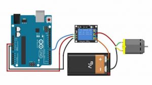
Wiring your relay can be done like this: | Wiring your relay can be done like this: | ||
| Line 26: | Line 26: | ||
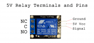
[[File:Relayterminalsandpint.png|300px]] | [[File:Relayterminalsandpint.png|300px]] | ||
| − | Now let's connect the motor to the relay. First connect the ground (-) of the power supply directly to the motor. The connect your | + | Now let's connect the motor to the relay. First connect the ground (-) of the power supply directly to the motor. Then connect the VCC (+) of your power supply to the middle terminal of the relay marked (COM). Lastly connect the other wire of the motor to the right terminal marked NO. |
| + | |||
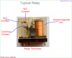
| + | A relay works as follows: When not receiving any power COM(common) is connected to NC (normally closed). When the signal pin received 5V, the relay switches and connects COM to NO, disconnecting COM and NC. Here is a picture of the inside: | ||
| + | |||
| + | [[File:Typical-electrical-relay-1930909437.png|300px]] | ||
| + | |||
| + | You have a choice: | ||
| + | |||
| + | If you want the power to be cut off normally, but only turn on when you give it power, you connect COM and NO. | ||
| + | |||
| + | If you want your motor to be powered normally, but only be cut of when you give the relay power, connect COM and NC. | ||
| + | |||
| + | <b> Programming your Arduino to control the relay </b> | ||
| + | |||
| + | To program your Arduino, you will need a program called Arduino IDE. This can be downloaded here: | ||
| + | |||
| + | https://www.arduino.cc/en/software | ||
| + | |||
| + | One's Arduino IDE is installed, start it and connect the Arduino with your computer using a USB B cable. Check if Arduino UNO pops up. If not, go to Tool > Port and check if you can find your device. Select it and go to Tool > Boards > Arduino AVR Boards and Select Arduino UNO. | ||
| + | |||
| + | Now we can start writing a sketch for the Arduino. I will post a basic sketch for your relay circuit: | ||
| + | |||
| + | <syntaxhighlight lang=c style="border:3px dashed pink"> | ||
| + | |||
| + | // Basic Relay Control Sketch | ||
| + | // This sketch demonstrates how to control a relay using an Arduino | ||
| + | // The relay will be turned on for 5 seconds, then off for 5 seconds in a loop | ||
| + | |||
| + | // Define the pin connected to the relay module | ||
| + | int relayPin = 2; // You can change this to any other digital pin | ||
| + | |||
| + | void setup() { | ||
| + | // Initialize the relay pin as an output | ||
| + | pinMode(relayPin, OUTPUT); | ||
| + | |||
| + | // Initially turn the relay off | ||
| + | digitalWrite(relayPin, LOW); | ||
| + | } | ||
| + | |||
| + | void loop() { | ||
| + | // Turn the relay on | ||
| + | digitalWrite(relayPin, HIGH); // HIGH turns the relay on | ||
| + | delay(5000); // Wait for 5 seconds (5000 milliseconds) | ||
| + | |||
| + | // Turn the relay off | ||
| + | digitalWrite(relayPin, LOW); // LOW turns the relay off | ||
| + | delay(5000); // Wait for 5 seconds (5000 milliseconds) | ||
| + | } | ||
| + | |||
| + | </syntaxhighlight> | ||
| + | Upload this sketch to your Arduino Uno using the right arrow button on the top left. See what happens. How can you tweak it to behave like you would like it to? | ||
| + | |||
| + | ===Multiple Relays=== | ||
| + | |||
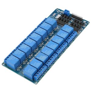
| + | The digital Pins of the Arduino UNO can control up to 13 relays. A bigger relay board allows you to make a sketch can controls multiple devices/motors whatever at once. | ||
| + | |||
| + | [[File:bigrelayboard.jpg|300px]] | ||
| + | |||
| + | ===Change direction with two relays=== | ||
| + | Using two relays, you can also reverse the polarity of your DC motor, effectively changing the direction of the rotation of the motor shaft. | ||
| + | |||
| + | <b>Wiring</b> | ||
| + | |||
| + | [[File:Schermafbeelding 2024-07-18 om 13.37.18.png|400px]] | ||
| + | |||
| + | - Connect the motor to the COM terminals of both relays. | ||
| + | - Connect the GND (-) to the NO terminals of both relays. | ||
| + | - Connect the VCC (+) to the NC terminals of both relays. | ||
| + | |||
| + | - Connect the relay pins to the 5V and GND of the Arduino. | ||
| + | - Connect the pins called IN1, IN2 or SIG to digital pin D2 and D3. | ||
| + | |||
| + | <b>Programming</b> | ||
| + | |||
| + | To program your Arduino to switch direction, we'll follow and example code made by Robojax. You can change the pins to the other digital pins on the Arduino, but note that pin 0 and 1 are used for serial communication. Picking between the pins 2 till 13 is a safer option. | ||
| + | |||
| + | |||
| + | <syntaxhighlight lang=c style="border:3px dashed pink"> | ||
| + | |||
| + | |||
| + | |||
| + | /* | ||
| + | * Arduino code change the direction of rotation | ||
| + | * of a DC motor with 2 relays. | ||
| + | * | ||
| + | * This is basic code. I have advanced code which can be used in both | ||
| + | * for Low-level trigger and High-lever trigger relay with clean code | ||
| + | * | ||
| + | * Written by Ahmad Shamshiri for Robojax.com on | ||
| + | * Sunday August 18, 2019 | ||
| + | * at 20:22 in Ajax, Ontario, Canada | ||
| + | * Watch video instruction for this code: https://youtu.be/JMBgGO07YLM | ||
| + | * | ||
| + | * | ||
| + | * | ||
| + | Get this code and other Arduino codes from Robojax.com | ||
| + | Learn Arduino step by step in structured course with all material, wiring diagram and library | ||
| + | all in once place. Purchase My course on Udemy.com http://robojax.com/L/?id=62 | ||
| + | |||
| + | If you found this tutorial helpful, please support me so I can continue creating | ||
| + | content like this. You can support me on Patreon http://robojax.com/L/?id=63 | ||
| + | |||
| + | or make donation using PayPal http://robojax.com/L/?id=64 | ||
| + | * | ||
| + | * This code is "AS IS" without warranty or liability. Free to be used as long as you keep this note intact.* | ||
| + | * This code has been download from Robojax.com | ||
| + | This program is free software: you can redistribute it and/or modify | ||
| + | it under the terms of the GNU General Public License as published by | ||
| + | the Free Software Foundation, either version 3 of the License, or | ||
| + | (at your option) any later version. | ||
| + | |||
| + | This program is distributed in the hope that it will be useful, | ||
| + | but WITHOUT ANY WARRANTY; without even the implied warranty of | ||
| + | MERCHANTABILITY or FITNESS FOR A PARTICULAR PURPOSE. See the | ||
| + | GNU General Public License for more details. | ||
| + | |||
| + | You should have received a copy of the GNU General Public License | ||
| + | along with this program. If not, see <https://www.gnu.org/licenses/>. | ||
| + | */ | ||
| + | |||
| + | |||
| + | int relay1 = 2; | ||
| + | int relay2 = 3; | ||
| + | |||
| + | |||
| + | void setup() { | ||
| + | |||
| + | pinMode(relay1, OUTPUT);// set pin as output for relay 1 | ||
| + | pinMode(relay2, OUTPUT);// set pin as output for relay 2 | ||
| + | |||
| + | |||
| + | // keep the motor off by keeping both HIGH | ||
| + | digitalWrite(relay1, HIGH); | ||
| + | digitalWrite(relay2, HIGH); | ||
| + | |||
| + | |||
| + | |||
| + | Serial.begin(9600);// initialize serial monitor with 9600 baud | ||
| + | Serial.println("Robojax Motor Direction of Rotation"); | ||
| + | Serial.println("Using 2 Relays"); | ||
| + | delay(2000); | ||
| + | } | ||
| + | |||
| + | void loop() { | ||
| + | |||
| + | // Rotate in CCW direction | ||
| + | digitalWrite(relay1, LOW);// turn relay 1 ON | ||
| + | digitalWrite(relay2, HIGH);// turn relay 2 OFF | ||
| + | Serial.println("Rotating in CCW"); | ||
| + | delay(3000);// wait for 3 seconds | ||
| + | |||
| + | // stop the motor | ||
| + | digitalWrite(relay1, HIGH);// turn relay 1 OFF | ||
| + | digitalWrite(relay2, HIGH);// turn relay 2 OFF | ||
| + | Serial.println("Stopped"); | ||
| + | delay(2000);// stop for 2 seconds | ||
| + | |||
| + | // Rotate in CW direction | ||
| + | digitalWrite(relay1, HIGH);// turn relay 1 OFF | ||
| + | digitalWrite(relay2, LOW);// turn relay 2 ON | ||
| + | Serial.println("Rotating in CW"); | ||
| + | delay(3000);// wait for 3 seconds | ||
| + | |||
| + | // stop the motor | ||
| + | digitalWrite(relay1, HIGH);// turn relay 1 OFF | ||
| + | digitalWrite(relay2, HIGH);// turn relay 2 OFF | ||
| + | Serial.println("Stopped"); | ||
| + | delay(2000);// stop for 2 seconds | ||
| + | |||
| + | Serial.println("==============="); | ||
| + | |||
| + | |||
| + | }// loop end | ||
| + | |||
| + | </syntaxhighlight> | ||
| + | |||
| + | Copy and paste this code into your Arduino IDE sketch and upload it. | ||
| + | |||
| + | |||
| + | |||
| + | For more information, watch this video by Robojax: | ||
| + | |||
| + | https://www.youtube.com/watch?v=JMBgGO07YLM&t=124s | ||
| + | |||
| + | |||
| + | ===Sensors=== | ||
| + | |||
| + | If you want your work to be interactive, you can connect the behavior of your relays to sensors. For more information about sensors, go to: | ||
| + | |||
| + | [[Sensors: Introduction and Types]] | ||
Latest revision as of 13:49, 18 July 2024
Using a relay for motor control
Relays are versatile electronic switches that can power on and off many devices. Here we will discuss a simple circuit to turn on and off your DC motor. In this example, we will use a Arduino UNO, but any microcontroller that outputs 5V on its digital pins will work. What you will need is the following:
1 x Computer 1 x USB A to USB B cable 1 x Arduino UNO (or other microcontroller) 1 x 5V relay board 1 x A dc motor 3 x jumper cables M-F
Wiring your motor with a relay
Wiring your relay can be done like this:
There are three pins on the board that allow you to connect the relay board to your Arduino. These should be connected as follows:
Arduino -> Relay Board
5V -> VCC GND -> GND D2 -> SIG/IN
Now let's connect the motor to the relay. First connect the ground (-) of the power supply directly to the motor. Then connect the VCC (+) of your power supply to the middle terminal of the relay marked (COM). Lastly connect the other wire of the motor to the right terminal marked NO.
A relay works as follows: When not receiving any power COM(common) is connected to NC (normally closed). When the signal pin received 5V, the relay switches and connects COM to NO, disconnecting COM and NC. Here is a picture of the inside:
You have a choice:
If you want the power to be cut off normally, but only turn on when you give it power, you connect COM and NO.
If you want your motor to be powered normally, but only be cut of when you give the relay power, connect COM and NC.
Programming your Arduino to control the relay
To program your Arduino, you will need a program called Arduino IDE. This can be downloaded here:
https://www.arduino.cc/en/software
One's Arduino IDE is installed, start it and connect the Arduino with your computer using a USB B cable. Check if Arduino UNO pops up. If not, go to Tool > Port and check if you can find your device. Select it and go to Tool > Boards > Arduino AVR Boards and Select Arduino UNO.
Now we can start writing a sketch for the Arduino. I will post a basic sketch for your relay circuit:
// Basic Relay Control Sketch
// This sketch demonstrates how to control a relay using an Arduino
// The relay will be turned on for 5 seconds, then off for 5 seconds in a loop

// Define the pin connected to the relay module
int relayPin = 2; // You can change this to any other digital pin

void setup() {
  // Initialize the relay pin as an output
  pinMode(relayPin, OUTPUT);

  // Initially turn the relay off
  digitalWrite(relayPin, LOW);
}

void loop() {
  // Turn the relay on
  digitalWrite(relayPin, HIGH); // HIGH turns the relay on
  delay(5000); // Wait for 5 seconds (5000 milliseconds)

  // Turn the relay off
  digitalWrite(relayPin, LOW); // LOW turns the relay off
  delay(5000); // Wait for 5 seconds (5000 milliseconds)
}
Upload this sketch to your Arduino Uno using the right arrow button on the top left. See what happens. How can you tweak it to behave like you would like it to?
Multiple Relays
The digital Pins of the Arduino UNO can control up to 13 relays. A bigger relay board allows you to make a sketch can controls multiple devices/motors whatever at once.
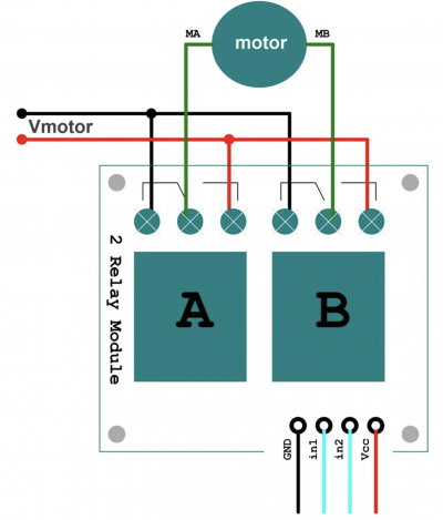
Change direction with two relays
Using two relays, you can also reverse the polarity of your DC motor, effectively changing the direction of the rotation of the motor shaft.
Wiring
- Connect the motor to the COM terminals of both relays. - Connect the GND (-) to the NO terminals of both relays. - Connect the VCC (+) to the NC terminals of both relays.
- Connect the relay pins to the 5V and GND of the Arduino. - Connect the pins called IN1, IN2 or SIG to digital pin D2 and D3.
Programming
To program your Arduino to switch direction, we'll follow and example code made by Robojax. You can change the pins to the other digital pins on the Arduino, but note that pin 0 and 1 are used for serial communication. Picking between the pins 2 till 13 is a safer option.
/*
 * Arduino code change the direction of rotation
 * of a DC motor with 2 relays.
 *
 * This is basic code. I have advanced code which can be used in both
 * for Low-level trigger and High-lever trigger relay with clean code
 *
 * Written by Ahmad Shamshiri for Robojax.com on
 * Sunday August 18, 2019
 * at 20:22 in Ajax, Ontario, Canada
 * Watch video instruction for this code: https://youtu.be/JMBgGO07YLM
 *
 *
 *
 Get this code and other Arduino codes from Robojax.com
Learn Arduino step by step in structured course with all material, wiring diagram and library
all in once place. Purchase My course on Udemy.com http://robojax.com/L/?id=62

If you found this tutorial helpful, please support me so I can continue creating
content like this. You can support me on Patreon http://robojax.com/L/?id=63

or make donation using PayPal http://robojax.com/L/?id=64
*
 * This code is "AS IS" without warranty or liability. Free to be used as long as you keep this note intact.*
 * This code has been download from Robojax.com
    This program is free software: you can redistribute it and/or modify
    it under the terms of the GNU General Public License as published by
    the Free Software Foundation, either version 3 of the License, or
    (at your option) any later version.

    This program is distributed in the hope that it will be useful,
    but WITHOUT ANY WARRANTY; without even the implied warranty of
    MERCHANTABILITY or FITNESS FOR A PARTICULAR PURPOSE.  See the
    GNU General Public License for more details.

    You should have received a copy of the GNU General Public License
    along with this program.  If not, see <https://www.gnu.org/licenses/>.
 */


int relay1 = 2;
int relay2 = 3;


void setup() {

    pinMode(relay1, OUTPUT);// set pin as output for relay 1
    pinMode(relay2, OUTPUT);// set pin as output for relay 2


    // keep the motor off by keeping both HIGH
    digitalWrite(relay1, HIGH);
    digitalWrite(relay2, HIGH);


  Serial.begin(9600);// initialize serial monitor with 9600 baud
  Serial.println("Robojax Motor Direction of Rotation");
  Serial.println("Using 2 Relays");
  delay(2000);
}

void loop() {

 // Rotate in CCW direction
  digitalWrite(relay1, LOW);// turn relay 1 ON
  digitalWrite(relay2, HIGH);// turn relay 2 OFF
  Serial.println("Rotating in CCW");
  delay(3000);// wait for 3 seconds

 // stop the motor
  digitalWrite(relay1, HIGH);// turn relay 1 OFF
  digitalWrite(relay2, HIGH);// turn relay 2 OFF
  Serial.println("Stopped");
  delay(2000);// stop for 2 seconds

 // Rotate in CW direction
  digitalWrite(relay1, HIGH);// turn relay 1 OFF
  digitalWrite(relay2, LOW);// turn relay 2 ON
  Serial.println("Rotating in CW");
  delay(3000);// wait for 3 seconds

 // stop the motor
  digitalWrite(relay1, HIGH);// turn relay 1 OFF
  digitalWrite(relay2, HIGH);// turn relay 2 OFF
  Serial.println("Stopped");
  delay(2000);// stop for 2 seconds

 Serial.println("===============");


}// loop end
Copy and paste this code into your Arduino IDE sketch and upload it.
For more information, watch this video by Robojax:
https://www.youtube.com/watch?v=JMBgGO07YLM&t=124s
Sensors
If you want your work to be interactive, you can connect the behavior of your relays to sensors. For more information about sensors, go to:
