Using a relay for motor control
Using a relay for motor control
Relays are versatile electronic switches that can power on and off many devices. Here we will discuss a simple circuit to turn on and off your DC motor. In this example, we will use a Arduino UNO, but any microcontroller that outputs 5V on its digital pins will work. What you will need is the following:
1 x Computer 1 x USB A to USB B cable 1 x Arduino UNO (or other microcontroller) 1 x 5V relay board 1 x A dc motor 3 x jumper cables M-F
Wiring your motor with a relay
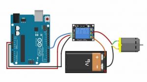
Wiring your relay can be done like this:
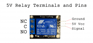
There are three pins on the board that allow you to connect the relay board to your Arduino. These should be connected as follows:
Arduino -> Relay Board
5V -> VCC GND -> GND D2 -> SIG/IN
Now let's connect the motor to the relay. First connect the ground (-) of the power supply directly to the motor. Then connect the VCC (+) of your power supply to the middle terminal of the relay marked (COM). Lastly connect the other wire of the motor to the right terminal marked NO.
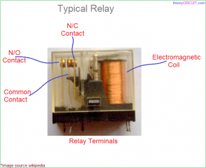
A relay works as follows: When not receiving any power COM(common) is connected to NC (normally closed). When the signal pin received 5V, the relay switches and connects COM to NO, disconnecting COM and NC. Here is a picture of the inside:
You have a choice:
If you want the power to be cut off normally, but only turn on when you give it power, you connect COM and NO.
If you want your motor to be powered normally, but only be cut of when you give the relay power, connect COM and NC.
Programming your Arduino to control the relay
To program your Arduino, you will need a program called Arduino IDE. This can be downloaded here:
https://www.arduino.cc/en/software
One's Arduino IDE is installed, start it and connect the Arduino with your computer using a USB B cable. Check if Arduino UNO pops up. If not, go to Tool > Port and check if you can find your device. Select it and go to Tool > Boards > Arduino AVR Boards and Select Arduino UNO.
Now we can start writing a sketch for the Arduino. I will post a basic sketch for your relay circuit:
// Basic Relay Control Sketch
// This sketch demonstrates how to control a relay using an Arduino
// The relay will be turned on for 5 seconds, then off for 5 seconds in a loop

// Define the pin connected to the relay module
int relayPin = 2; // You can change this to any other digital pin

void setup() {
  // Initialize the relay pin as an output
  pinMode(relayPin, OUTPUT);

  // Initially turn the relay off
  digitalWrite(relayPin, LOW);
}

void loop() {
  // Turn the relay on
  digitalWrite(relayPin, HIGH); // HIGH turns the relay on
  delay(5000); // Wait for 5 seconds (5000 milliseconds)

  // Turn the relay off
  digitalWrite(relayPin, LOW); // LOW turns the relay off
  delay(5000); // Wait for 5 seconds (5000 milliseconds)
}
Upload this sketch to your Arduino Uno using the right arrow button on the top left. See what happens. How can you tweak it to behave like you would like it to?
Multiple Relays
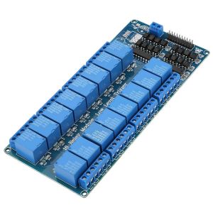
The digital Pins of the Arduino UNO can control up to 13 relays. A bigger relay board allows you to make a sketch can controls multiple devices/motors whatever at once.
Using two relays, you can also reverse the polarity of your DC motor. For more information on this, go to Reverse motor polarity with two relays.
Sensors
If you want your work to be interactive, you can connect the behavior of your relays to sensors. For more information about sensors, go to:


