Difference between revisions of "Week 3"
| (3 intermediate revisions by 2 users not shown) | |||
| Line 34: | Line 34: | ||
<br> | <br> | ||
[[File:Pressure.png]] | [[File:Pressure.png]] | ||
| + | ===Pull down/up=== | ||
| + | <br> | ||
| + | Pull-down or pull-up resistors are used in electronic logic circuits to ensure that inputs to the arduino settle at expected logic levels. ''Just because you have nothing at all connected to an input pin doesn't mean it is a logical zero.'' | ||
| + | <br> | ||
| + | A pull-down resistor weakly "pulls" the voltage of the wire it is connected to towards ground when the other components on the line are inactive. When the switch on the line is open, it acts like it is disconnected. Since the other components act as though they are disconnected, the circuit acts as though it is disconnected, and the pull-down resistor brings the wire down to the low logic level. When another component on the line goes active, it will override the low logic level set by the pull-down resistor. The pull-down resistor assures that the wire is at a defined logic level even if no active devices are connected to it. | ||
| + | <br> | ||
| + | [[File:Pulldown Resistor.png]] | ||
| + | <br><br> | ||
| + | |||
| + | A pull-up resistor works in the same way but is connected to the voltage source. It holds the logic signal high when no other active device is connected. | ||
| + | <br> | ||
| + | [[File:Pullup Resistor.png]] | ||
| + | <br><br> | ||
| + | |||
| + | The value of a pull down or pull up resistor will vary depending upon your specific devices involved. | ||
| + | <br> | ||
| + | |||
====Read the Sensor==== | ====Read the Sensor==== | ||
| Line 89: | Line 106: | ||
} | } | ||
</syntaxhighlight> | </syntaxhighlight> | ||
| + | <br> | ||
| + | ====Add a threshold value==== | ||
| − | == | + | <syntaxhighlight lang=c style="border:3px dashed blue"> |
| − | + | ||
| − | + | const int led = 3; | |
| − | + | const int sensor= A0; | |
| − | + | const int threshold = 10; | |
| − | + | ||
| − | + | int fadeval = 0; | |
| − | |||
| − | + | // the setup routine runs once when you press reset: | |
| − | + | void setup() { | |
| − | + | // initialize serial communication at 9600 bits per second: | |
| − | + | Serial.begin(9600); | |
| + | // initialize led pin as an output: | ||
| + | pinMode(led, OUTPUT); | ||
| + | |||
| + | } | ||
| − | + | // the loop routine runs over and over again forever: | |
| − | < | + | void loop() { |
| + | int sensorValue = analogRead(sensor); | ||
| + | //Serial.println (sensorValue); | ||
| + | fadeval = map(sensorValue, 0, 1023, 0, 255); | ||
| + | if (fadeval > threshold) { | ||
| + | analogWrite( led, fadeval); | ||
| + | }else{ | ||
| + | analogWrite (led, LOW); | ||
| + | } | ||
| + | delay(1); // delay in between reads for stability | ||
| + | Serial.println (sensorValue); | ||
| + | } | ||
| + | </syntaxhighlight> | ||
| + | [[Category:2017]] | ||
Latest revision as of 12:58, 20 January 2023
Making pressure and bend sensors
One of the most powerful tools you can plug into your Arduino is a sensor, a small electronic device that enables the microcontroller to take readings from its surroundings, reacting in accordance to its program.
Digital and analog are two methods of transmitting information. The Arduino world uses both methods.
The Arduino reserves some pins for digital input and output, and others for analog. A servo’s data wire plugs into a digital pin, whereas an analog light sensor sends its data reading to an analog pin.
Which pins are which? You can easily tell just by looking at the Arduino.
Digital Sensors
Digital sensors are the sensors that gives 2 state (on/off, 5V/0V). You will connect them to digital Pins and set it as INPUT.
Digital data consists exclusively of 0s and 1s .
For example, consider a push button switch. This is one of the simplest forms of sensors. It has two discrete values. It is on, or it is off. Other 'discrete' sensors might provide you with a binary value.
Another example of a digital sensor is an accelerometer, which sends a series of data points (speed, direction, and so on) to the Arduino. Usually digital sensors need a chip in the sensor to interpret the physical data.
Analog Sensors
Analog sensors on the other hand, gives range. You connect this types of Analog sensors to Analog Input pins which is measuring the incoming voltage between 0V-5V*. Arduino converts this incoming voltage into the number between 0-1023.
Analog data is transmitted as a continuous signal, almost like a wave. In other words, an analog sensor doesn’t send a burst of 1s and 0s like digital sensors do; instead, the sensor modulates a continuous signal to transmit data.
Pressure sensor / Force Sensitive Resistor
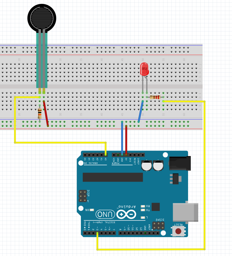
The resistance of an FSR varies as the force on the sensor increases or decreases. When no pressure is being applied to the FSR, its resistance will be larger than 1MΩ. The harder you press on the sensor’s head, the lower the resistance between the two terminals drops.

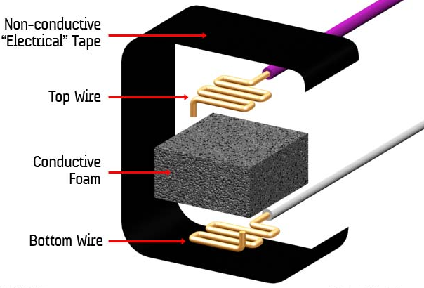
Basically, the conductive foam in which many ICs are shipped is, well, conductive. It has a high resistance, but that resistance decreases when the foam is compressed — in other words, a sort of primitive variable resistor. I used this property to create a basic pressure sensor. We will place a small square of foam between two conductive materials. The object must be secured ( held in place) by tape, or other means.
It’s definitely not a precision instrument, however. But, hey it is a self-made sensor and it works!

Pull down/up
Pull-down or pull-up resistors are used in electronic logic circuits to ensure that inputs to the arduino settle at expected logic levels. Just because you have nothing at all connected to an input pin doesn't mean it is a logical zero.
A pull-down resistor weakly "pulls" the voltage of the wire it is connected to towards ground when the other components on the line are inactive. When the switch on the line is open, it acts like it is disconnected. Since the other components act as though they are disconnected, the circuit acts as though it is disconnected, and the pull-down resistor brings the wire down to the low logic level. When another component on the line goes active, it will override the low logic level set by the pull-down resistor. The pull-down resistor assures that the wire is at a defined logic level even if no active devices are connected to it.

A pull-up resistor works in the same way but is connected to the voltage source. It holds the logic signal high when no other active device is connected.

The value of a pull down or pull up resistor will vary depending upon your specific devices involved.
Read the Sensor
const int sensor= A0;


// the setup routine runs once when you press reset:
void setup() {
  // initialize serial communication at 9600 bits per second:
  Serial.begin(9600);


}

// the loop routine runs over and over again forever:
void loop() {
  int sensorValue = analogRead(sensor);
  Serial.println (sensorValue);
  delay(1);        // delay in between reads for stability

}
Map the values so we can control an led
const int led = 3;
const int sensor= A0;

int fadeval = 0;

// the setup routine runs once when you press reset:
void setup() {
  // initialize serial communication at 9600 bits per second:
  Serial.begin(9600);
 // initialize led pin as an output:
  pinMode(led, OUTPUT);

}

// the loop routine runs over and over again forever:
void loop() {
  int sensorValue = analogRead(sensor);
 fadeval = map(sensorValue, 0, 1023, 0, 255);
 analogWrite( led, fadeval);
 delay(1);        // delay in between reads for stability
 //Serial.println (sensorValue);
}
Add a threshold value
const int led = 3;
const int sensor= A0;
const int threshold = 10;

int fadeval = 0;

// the setup routine runs once when you press reset:
void setup() {
  // initialize serial communication at 9600 bits per second:
  Serial.begin(9600);
 // initialize led pin as an output:
  pinMode(led, OUTPUT);

}

// the loop routine runs over and over again forever:
void loop() {
  int sensorValue = analogRead(sensor);
  //Serial.println (sensorValue);
  fadeval = map(sensorValue, 0, 1023, 0, 255);
  if (fadeval > threshold) {
  analogWrite( led, fadeval);
  }else{
  analogWrite (led, LOW);
  }
  delay(1);        // delay in between reads for stability
  Serial.println (sensorValue);
}