Difference between revisions of "Visualizing sound in TouchDesigner"
| (2 intermediate revisions by the same user not shown) | |||
| Line 1: | Line 1: | ||
| − | You can follow this tutorial to generate a dynamic sound wave in TouchDesigner starting from a sound file. | + | |
| + | You can follow this tutorial to generate a dynamic sound wave in TouchDesigner starting from a sound file.<br> | ||
| + | Here an [https://interactionstation.wdka.hro.nl/mediawiki/images/d/d1/Smallest.mp4 example]. | ||
=Importing your sound file into TouchDesigner= | =Importing your sound file into TouchDesigner= | ||
Latest revision as of 09:24, 21 March 2024
You can follow this tutorial to generate a dynamic sound wave in TouchDesigner starting from a sound file.
Here an example.
Importing your sound file into TouchDesigner
- Open TouchDesigner
- Remove the example network and get a blank view
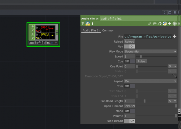
- Add your sound file: you can do this by directly dragging it inside the software view. It will automatically create a Audio File In named as the original file. Alternatively, you can add a Audio File In CHOP by double clicking on the pane view. You can then select your file from the operator menu.
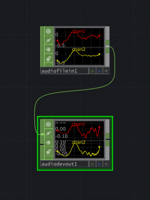
- Add an Audio Device out and link it to your sound file. In this way you will be able to hear it. A file on its own will not automatically play without it.
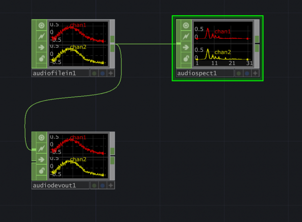
- You might have noticed how the program is already giving you a visualisation of the audio file. Add a Audio Spectrum CHOP to display the frequency spectrum of the audio file.
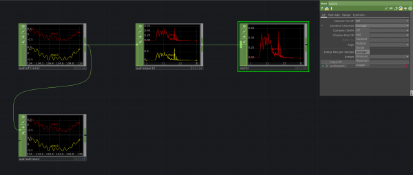
- By default you will see the audio spectrum as a stereo view, visualising the two channels. You can turn this into one by adding a Math CHOP.
In the menu you should set:
Combine Channels : Average
This option will merge the two channels into one.
Turning the CHOP view into an image
At this point you are seeing the audio spectrum of your file as a single graph. This image though is only the visualisation of a CHOP operator and not an image. CHOPS only understand channels of numerical data. We now need to turn this into an image - in this case a TOP.
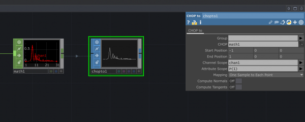
- From the exit point of your last Math block right click to see which operator can be link to it. We will select a CHOP to SOP. SOPs are are operators that can generate, import, modify and combine 3D geometries. We are using this to be able to translate the axis diagram into an image.
In the menu you should set:
Channel scope : chan1
(the channel name of your Math CHOP)
Attribute scope: P(1)
(This option will only select the Point Position on the Y Axis, the one we need to visualise)
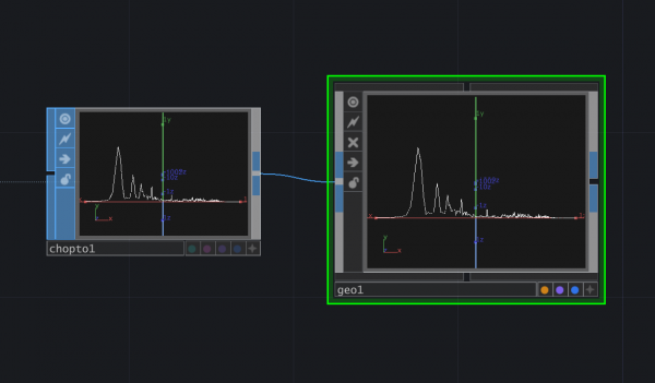
- Connect the CHOP to SOP to a Geometry COMP. Do it by right clicking on the exit point of the last operator.
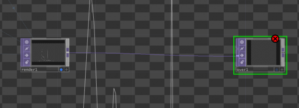
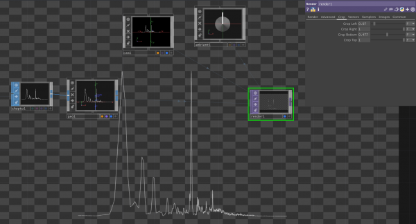
- Double click on the pane and add a Render TOP. You use this to render all 3D scenes. By default it will link to your geometry. At this point the graph is not visible. To make it visible we need to add a Camera and an Ambient Light COMP. They will both connect to the Render automatically. Now you should be able to see your sound wave image at the center of the Render TOP.
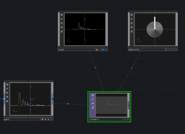
We can now do things like aligning the image to the bottom by using the Crop settings on the Render menu.
Add a Feedback Loop
At this point we managed to have our moving image out of the sound track. We are going to add a Feedback effect to it.
- Add an Over TOP. The Over TOP is used to combine two inputs, adding the Input1 over the Input2. We are going to drag the render into the 2nd input of the Over TOP.
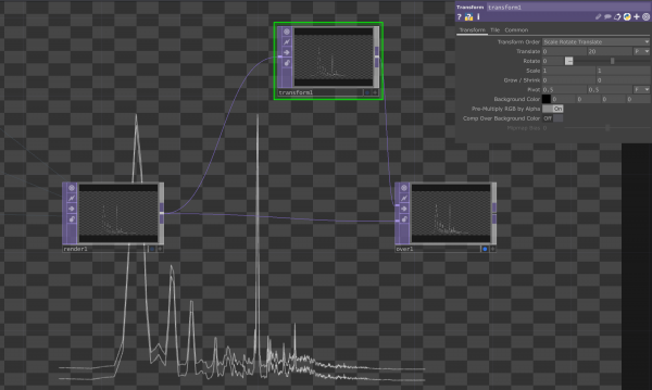
- Add a Transform TOP. Use the Render as an input and the over as an output. In the Transform menu change the Translate values to move the graph slightly up from its original spot. You can also change the unit from Fraction to Pixels.
You will now notice that another graph has been added on the Over operator.
- Add a Feedback TOP in between the Render and the Transform TOPs. You can do this by right clicking on the joint and select Insert Operator.
In the Feedback TOP menu place the Over operator under the Target TOP parameter. You can write here the name of the operator.
You should now see how the Feedback operator is creating a loop that keeps adding layer at the distance determined in the Transform. You can of course have this loop with any other TOP.
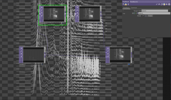 You can now style your sound wave in the way you like using other TOPs.
Add a button to re-start the Loop
At this point your image will keep adding layers on the top of each other. But what if we want to clear out our image?
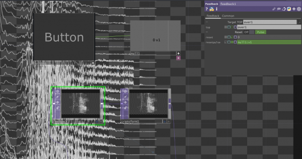
In the Feedback menu you can find an option to Reset. By clicking on the Pulse button you can restart the loop.
You can also trigger the Pulse from another parameter, like a Timer CHOP (to restart after a certain amount of time) or by pressing a certain key with a Keyboard In CHOP. We are going to use the Button COMP.
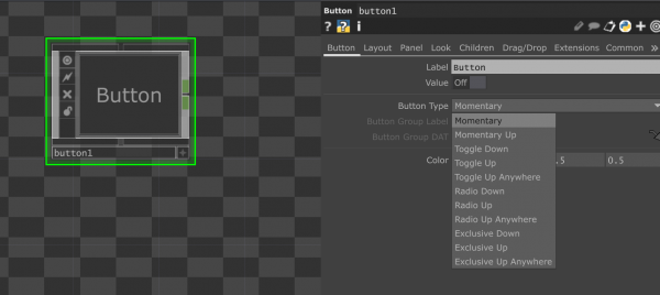
- Add a Button COMP. In the menu select Button Type: Momentary. This way the button state is changing only when pressed. Make the button active by clicking on the * symbol at the bottom right corner of the operator. Now you should be able to trigger it by pressing it.
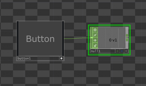
- Add a Null CHOP and connect it to the button. You will see the value change when pressing the button.
- Make the Null CHOP active and "drag" it into the Reset Pulse option in the Feedback operator menu. Once the Null is active you will see it turning green when hovering it. Click on it and drag it in the Feedback parameter where you wish to export the value. An arrow symbol will appear when hovering the cell you wich to export your CHOP in.
Now you can restart the loop by pressing the button.
