Difference between revisions of "TouchDesigner & Arduino"
| (3 intermediate revisions by the same user not shown) | |||
| Line 2: | Line 2: | ||
You can use Arduino to send (sensor) data to TouchDesigner and vice versa. | You can use Arduino to send (sensor) data to TouchDesigner and vice versa. | ||
| − | For example, you might want to measure the light condition of a room and use this data to trigger something in TouchDesigner. Or you might want to be able to have | + | For example, you might want to measure the light condition of a room and use this data to trigger something in TouchDesigner. Or you might want to be able to have lights react to a sound, or a motor spin in sync with a projection.<br> |
| + | |||
| + | Some applications:<br> | ||
| + | * https://www.behance.net/gallery/132238433/Interactive-Graphics-Arduino-TouchDesigner?locale=en_US | ||
| + | * https://www.lumus-instruments.com/project-detail/6138a1c91b37f52157057818 | ||
| + | * https://www.collectifscale.com/ | ||
| + | * https://ars.electronica.art/starts-prize/en/cmd/ | ||
| + | |||
To do so there are typically to methods that can be used: | To do so there are typically to methods that can be used: | ||
| − | |||
*Serial Communication | *Serial Communication | ||
With this method you are making Arduino & TD talk to each other by using Serial, a communication protocol that is able to send info essentially through a wire (the usb wire that connect the board to the computer running TD). TD has a '''Serial DAT''' operator that is able to receive this data. <br> | With this method you are making Arduino & TD talk to each other by using Serial, a communication protocol that is able to send info essentially through a wire (the usb wire that connect the board to the computer running TD). TD has a '''Serial DAT''' operator that is able to receive this data. <br> | ||
This method is preferred when your Arduino needs to use library or specific code to gather data from the sensors you are using. | This method is preferred when your Arduino needs to use library or specific code to gather data from the sensors you are using. | ||
| − | + | *Firmata | |
| + | Build-in option in TD Palette that enables communication directly to the Arduino Pins. Easy to use on the Arduino side as there is no need to code there. Smooth and easy to use but not an option if working with libraries or custom code. | ||
= Using Serial Communication= | = Using Serial Communication= | ||
| Line 216: | Line 223: | ||
:Here is the full code: <br> | :Here is the full code: <br> | ||
<syntaxhighlight lang="c"> | <syntaxhighlight lang="c"> | ||
| − | |||
//LDR PIN and VARIABLE | //LDR PIN and VARIABLE | ||
int sensorPin = A0; // select the input pin for LDR | int sensorPin = A0; // select the input pin for LDR | ||
| Line 225: | Line 231: | ||
const int sensorEchoPin = 3; // Connect to the echo pin of HC-SR04 | const int sensorEchoPin = 3; // Connect to the echo pin of HC-SR04 | ||
const int glitchThreshold = 2000; // Threshold for excluding glitchy readings | const int glitchThreshold = 2000; // Threshold for excluding glitchy readings | ||
| + | int distance; | ||
| + | |||
| + | // Variables | ||
int readings[WINDOW_SIZE]; // Array to store recent sensor readings | int readings[WINDOW_SIZE]; // Array to store recent sensor readings | ||
int index = 0; // Index for circular buffer | int index = 0; // Index for circular buffer | ||
long sum = 0; // Sum of recent readings | long sum = 0; // Sum of recent readings | ||
| − | // | + | //LEDs |
| − | |||
#define led_kick 6 | #define led_kick 6 | ||
#define led_snare 7 | #define led_snare 7 | ||
#define led_rythm 8 | #define led_rythm 8 | ||
| + | |||
| + | |||
void setup() { | void setup() { | ||
| Line 243: | Line 253: | ||
pinMode(sensorEchoPin, INPUT); | pinMode(sensorEchoPin, INPUT); | ||
| − | + | //leds | |
pinMode(led_kick, OUTPUT); | pinMode(led_kick, OUTPUT); | ||
pinMode(led_snare, OUTPUT); | pinMode(led_snare, OUTPUT); | ||
| Line 252: | Line 262: | ||
//getting and printing sensor data from LDR | //getting and printing sensor data from LDR | ||
sensorValue = analogRead(sensorPin); // read the value from the sensor | sensorValue = analogRead(sensorPin); // read the value from the sensor | ||
| − | + | ||
| − | |||
//getting sensor data from ultrasonic sensor | //getting sensor data from ultrasonic sensor | ||
| Line 283: | Line 292: | ||
// Convert movingAverage to an integer | // Convert movingAverage to an integer | ||
| − | + | distance = static_cast<int>(movingAverage); | |
| − | |||
| − | |||
| − | |||
} | } | ||
| − | + | //print the light sensor value | |
| − | + | Serial.print(sensorValue); | |
| − | + | Serial.print(" "); | |
| − | + | // Print the distance | |
| − | + | Serial.println(distance); | |
| + | |||
| + | if (Serial.available()>0){ | ||
| + | int incomingByte = Serial.read(); | ||
| + | |||
| + | if (incomingByte == 1){ | ||
| + | digitalWrite(led_kick, HIGH); | ||
| + | digitalWrite(led_snare, LOW); | ||
| + | digitalWrite(led_rythm, LOW); | ||
| + | } | ||
| + | else if (incomingByte == 2){ | ||
| + | digitalWrite(led_kick, LOW); | ||
| + | digitalWrite(led_snare, HIGH); | ||
| + | digitalWrite(led_rythm, LOW); | ||
| + | } | ||
| + | else if (incomingByte == 3){ | ||
| + | digitalWrite(led_kick, LOW); | ||
| + | digitalWrite(led_snare, LOW); | ||
| + | digitalWrite(led_rythm, HIGH); | ||
| + | } | ||
| + | } else { | ||
| + | digitalWrite(led_kick, LOW); | ||
| + | digitalWrite(led_snare, LOW); | ||
| + | digitalWrite(led_rythm, LOW); | ||
| + | } | ||
| + | |||
| − | |||
| − | |||
| − | |||
| − | |||
| − | |||
| − | |||
| − | |||
| − | |||
| − | |||
| − | |||
| − | |||
| − | |||
| − | |||
| − | |||
| − | |||
| − | |||
| − | |||
| − | |||
| − | |||
| − | |||
} | } | ||
| + | |||
</syntaxhighlight> | </syntaxhighlight> | ||
: Before uploading the code on the board set the Serial DAT on TD to '''Active: off'''. Activate it back when the code is uploaded. <br> | : Before uploading the code on the board set the Serial DAT on TD to '''Active: off'''. Activate it back when the code is uploaded. <br> | ||
Latest revision as of 12:04, 27 May 2024
You can use Arduino to send (sensor) data to TouchDesigner and vice versa.
For example, you might want to measure the light condition of a room and use this data to trigger something in TouchDesigner. Or you might want to be able to have lights react to a sound, or a motor spin in sync with a projection.
Some applications:
- https://www.behance.net/gallery/132238433/Interactive-Graphics-Arduino-TouchDesigner?locale=en_US
- https://www.lumus-instruments.com/project-detail/6138a1c91b37f52157057818
- https://www.collectifscale.com/
- https://ars.electronica.art/starts-prize/en/cmd/
To do so there are typically to methods that can be used:
- Serial Communication
With this method you are making Arduino & TD talk to each other by using Serial, a communication protocol that is able to send info essentially through a wire (the usb wire that connect the board to the computer running TD). TD has a Serial DAT operator that is able to receive this data.
This method is preferred when your Arduino needs to use library or specific code to gather data from the sensors you are using.
- Firmata
Build-in option in TD Palette that enables communication directly to the Arduino Pins. Easy to use on the Arduino side as there is no need to code there. Smooth and easy to use but not an option if working with libraries or custom code.
Using Serial Communication
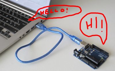
Serial communication is a method for transferring data between devices. It is able to send data sequentially over a wire. In this case the USB cable that connects your Arduino with the computer running TD.
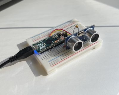
For this example we are getting sensor data from a LDR and a Ultrasonic sensor, sensing light values and distance.
Arduino to TouchDesigner
Arduino wiring and code
First we wire the sensors to Arduino and upload the code to the board. The following example uses a LDR (light sensor) and an Ultrasonic sensor (distance sensor).
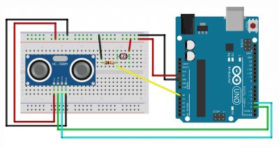
Follow the wiring diagram as in Pic 2:
LDR
- Connect one side to 5V;
- Connect the other side to GND through a 10kOhm Resistor. Connect this same side to the A0 pin on the Arduino board.
HCSR04 ULTRASONIC SENSOR
- Connect the sensor GND pin to GND;
- Connect the sensor VCC pin to 5V;
- Connect the Echo pin to Digital Pin 3 of the Arduino Board;
- Connect the Trigger pin to Digital Pin 2 of the Arduino Board;
Here is the code:
//LDR PIN and VARIABLE
int sensorPin = A0; // select the input pin for LDR
int sensorValue = 0; // variable to store the value coming from the sensor
//ULTRASONIC SENSOR PIN and VARIABLEs
const int WINDOW_SIZE = 10; // Adjust the window size as needed
const int sensorTriggerPin = 2; // Connect to the trigger pin of HC-SR04
const int sensorEchoPin = 3; // Connect to the echo pin of HC-SR04
const int glitchThreshold = 2000; // Threshold for excluding glitchy readings

int distance;

// Variables
int readings[WINDOW_SIZE]; // Array to store recent sensor readings
int index = 0; // Index for circular buffer
long sum = 0; // Sum of recent readings

void setup() {
  //start serial communication
  Serial.begin(9600); //sets serial port for communication

 //define ultrasonic sensor pin as in or out
    pinMode(sensorTriggerPin, OUTPUT);
    pinMode(sensorEchoPin, INPUT);
}

void loop() {
  //getting and printing sensor data from LDR
    sensorValue = analogRead(sensorPin); // read the value from the sensor


  //getting sensor data from ultrasonic sensor
    // Trigger the sensor
    digitalWrite(sensorTriggerPin, LOW);
    delayMicroseconds(2);
    digitalWrite(sensorTriggerPin, HIGH);
    delayMicroseconds(10);
    digitalWrite(sensorTriggerPin, LOW);

    // Read the echo pulse duration
    long duration = pulseIn(sensorEchoPin, HIGH);

    // Calculate distance in centimeters
    float distance_cm = duration * 0.034 / 2;

    // Exclude glitchy readings
    if (distance_cm < glitchThreshold) {
        // Add the new reading to the window
        sum -= readings[index]; // Subtract the oldest reading
        readings[index] = distance_cm; // Store the new reading
        sum += distance_cm; // Add the new reading

        // Increment the index (circular buffer)
        index = (index + 1) % WINDOW_SIZE;

        // Calculate the moving average
        float movingAverage = static_cast<float>(sum) / WINDOW_SIZE;

        // Convert movingAverage to an integer
        distance = static_cast<int>(movingAverage);

    }

        //print the light sensor value
        Serial.print(sensorValue);
        Serial.print(" ");
        // Print the distance
        Serial.println(distance);
        // add a delay - slow down data flow
        delay(10);
}
By opening the serial monitor you can check the data coming from the sensors. The LDR one is going to appear as a number going from 0 to 1023 while the ultrasonic sensor value is expressed in cm.
Once we checked that everything works smooth we are going to close the serial monitor window.
Getting the data in TouchDesigner
1. Open the Serial DAT
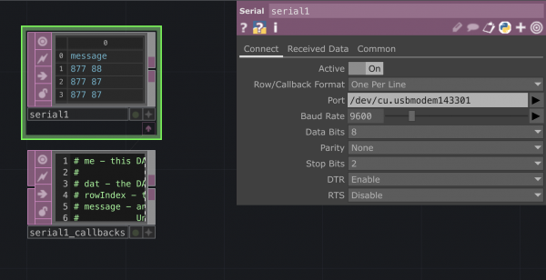
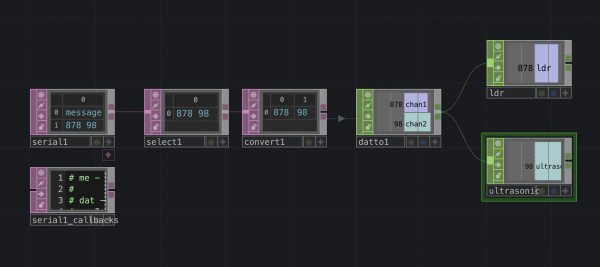
- In the panel you should set it on Active and select the callback format. Select the port where you have your Arduino connected. You should now see the numbers that you were previously seeing on the Arduino serial monitor appearing in the Serial DAT.
2. Select DAT
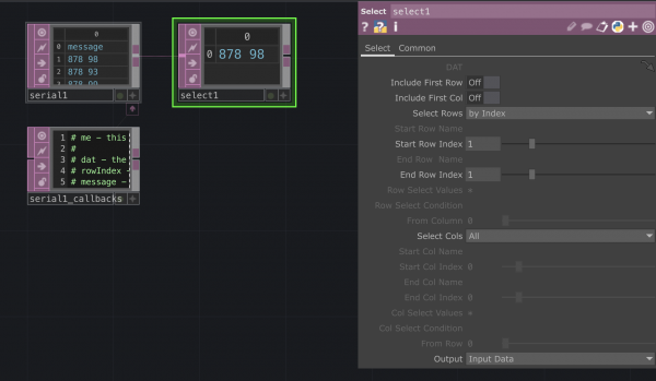
- When getting the data in we are seeing that the Serial DAT is printing a line saying "message". We are going to get rid of it with the Select DAT.
3. Convert DAT
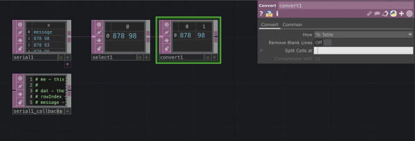
- We are now using a Convert DAT to be able to split our row into two columns so that we can eventually target each value separately. To do so we using the Split Cells option: instead of using the default \t we are going to do it at each space.
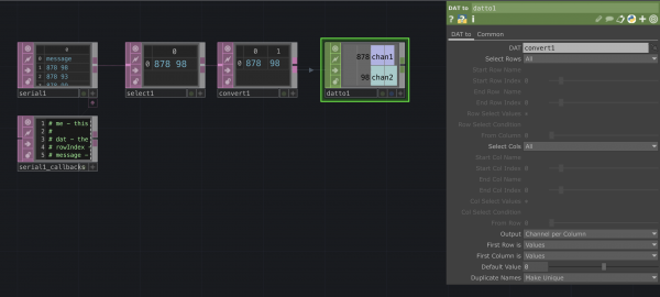
- We need now to convert our DAT into a CHOP. We can use the DAT to operator in the CHOPs menu. Inside the panel we have to set:
- Output: Channel per column
- Fist Row: Values
- First Column:Values
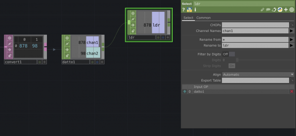
- Once you assigned each value to a channel to can use a Select CHOP to split them into two different operators. You can also rename the channel.
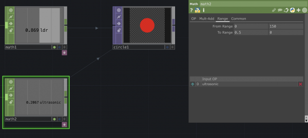
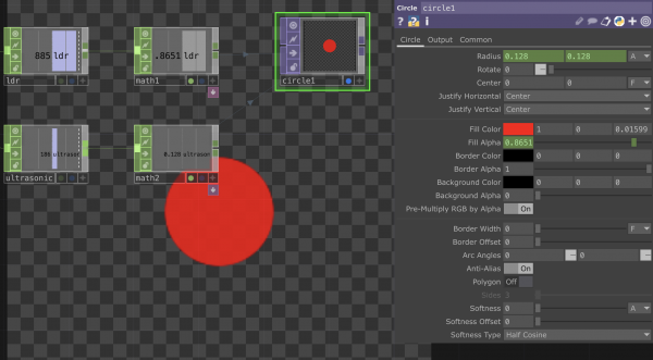
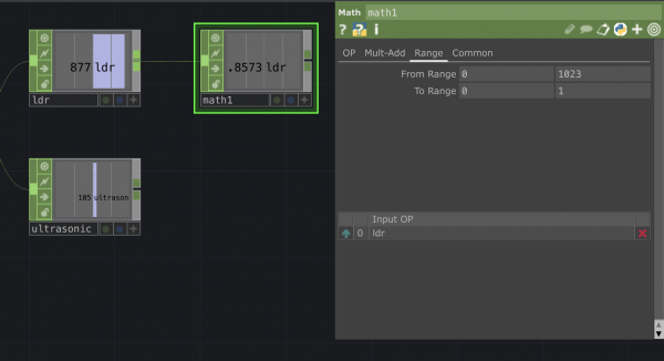
- Because we are receiving the sensor data in ranges that might not be suitable with what we want to trigger in TD we can use a Math CHOP to adjust the values to the desired range. In this case I want to remap the values coming from the sensor from 0-1023 to 0-1.
7.Use LDR data to trigger the alpha
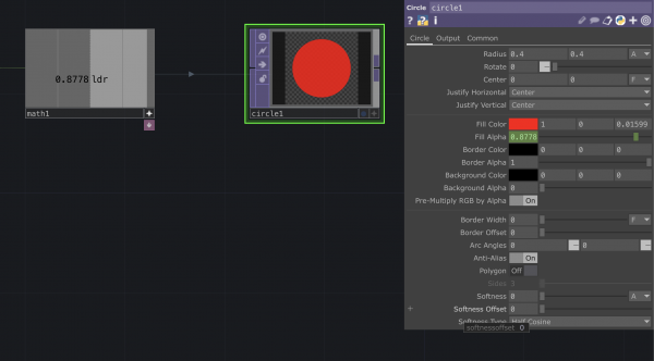
- You can now use the remapped value to trigger the op value that you want. In this case I am using the light sensor data to affect the alpha level of a Circle TOP.
8.Trigger the circle size with distance sensor data
- We can do something similar with the distance data. You can once again use the Math CHOP to remap the distance values to trigger the dimensions of the circle.
TouchDesigner to Arduino
We manage to send data from Arduino to TouchDesigner. We can now do it the other way around. In the same TD project we are going to add another functionality, where this time the data will flow from TD to Arduino. To do so we are going to make TD analyse a sound file and its parameters to have real time audio reactive LEDs in Arduino.
Connecting the LEDs
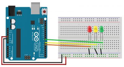
Add 3 LEDs to your breadboard set up - we will add this to the previous set up - don't remove the sensors.
Follow the wiring diagram as:
- Place the three LEDs on the breadboard
- Connect the short legs of the LEDs to Arduino's ground;
- Connect the long leg of the 1st LED to Digital Pin 6;
- Connect the long leg of the 2nd LED to Digital Pin 7;
- Connect the long leg of the 3rd LED to Digital Pin 8;
Audio analysis from TD to Arduino
1. Add an audio file
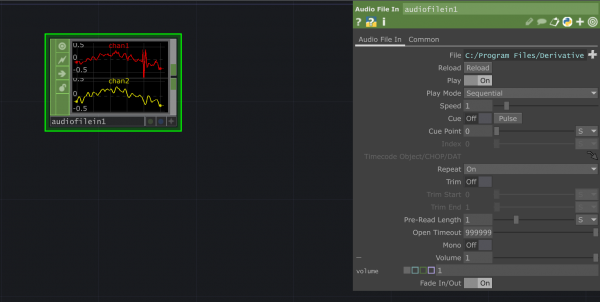
- In the CHOP list select the Audio File In. you can replace the file from the op menu. You can also use a Audio Device In alternatively. To be able to hear it you can connect it to the Audio Device Out CHOP.
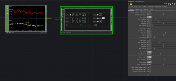
- We are now adding the Audio Analysis component. You can find this in the Palette menu (usually on the left side). Drag it into the pane and connect it to the audio file. In the menu you can see all the different controls. We are going to set the Kick, Snare and Rhythm to Active and define the threshold. When the correspondent value crosses the threshold it will pulse. We will use these pulses to trigger the LEDs.
- Connect a Select CHOP and pick the kick, snare and rhythm channels.
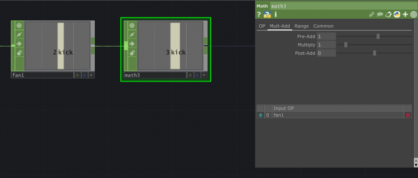
- We now have three different channels: we are using a Fan CHOP to bring it to one. Add a Fan CHOP and set the Operation to Fan In: this option is used to make into one channel a series of binary input like the ones we have. The result is a number that moves from 0 to 2 accordingly to the channel that is pulsing in that moment: 0 is the kick, 1 is the snare and 2 is the rhythm.
- We use a Math CHOP to add 1 to our number
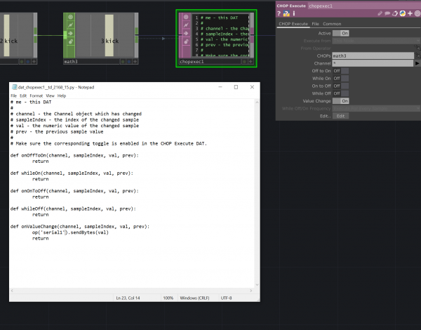
- We add a CHOP Execute DAT. In the menu we make sure we connect it to the corresponding CHOP.
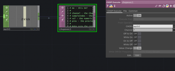
We then press Edit. At this point a window with some Python code will appear. We make sure we change it to:
# me - this DAT
#
# channel - the Channel object which has changed
# sampleIndex - the index of the changed sample
# val - the numeric value of the changed sample
# prev - the previous sample value
#
# Make sure the corresponding toggle is enabled in the CHOP Execute DAT.

def onOffToOn(channel, sampleIndex, val, prev):
	return

def whileOn(channel, sampleIndex, val, prev):
	return

def onOnToOff(channel, sampleIndex, val, prev):
	return

def whileOff(channel, sampleIndex, val, prev):
	return

def onValueChange(channel, sampleIndex, val, prev):
	op('serial1').sendBytes(val)
	return
We use this code to send our CHOP value to the Serial operator (in this case serial1) so that it can go to Arduino.
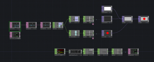
Here is a overview of the network we have been building:
Receiving the data in Arduino
1. Update the Arduino code
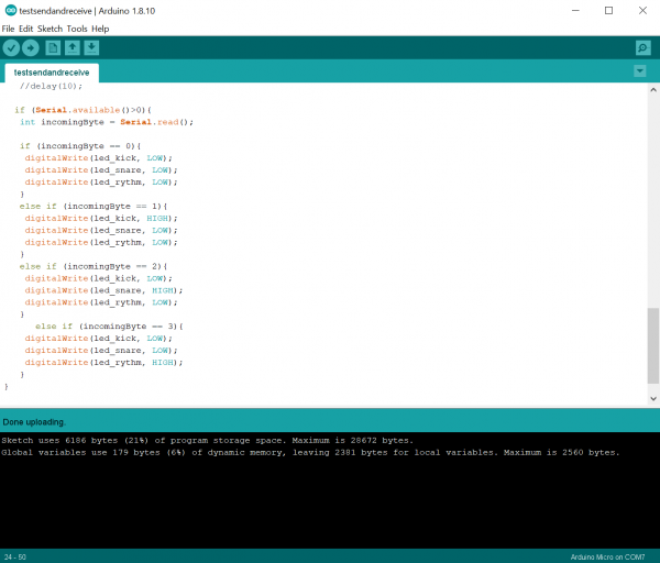
- We are going to add to our Arduino sketch some code to be able to receive the serial messages and trigger the LEDs.
- Here is the full code:
//LDR PIN and VARIABLE
int sensorPin = A0; // select the input pin for LDR
int sensorValue = 0; // variable to store the value coming from the sensor
//ULTRASONIC SENSOR PIN and VARIABLEs
const int WINDOW_SIZE = 10; // Adjust the window size as needed
const int sensorTriggerPin = 2; // Connect to the trigger pin of HC-SR04
const int sensorEchoPin = 3; // Connect to the echo pin of HC-SR04
const int glitchThreshold = 2000; // Threshold for excluding glitchy readings
int distance;

// Variables
int readings[WINDOW_SIZE]; // Array to store recent sensor readings
int index = 0; // Index for circular buffer
long sum = 0; // Sum of recent readings

//LEDs
#define led_kick 6
#define led_snare 7
#define led_rythm 8


void setup() {
  //start serial communication
  Serial.begin(9600); //sets serial port for communication

 //define ultrasonic sensor pin as in or out
    pinMode(sensorTriggerPin, OUTPUT);
    pinMode(sensorEchoPin, INPUT);

     //leds
    pinMode(led_kick, OUTPUT);
    pinMode(led_snare, OUTPUT);
    pinMode(led_rythm, OUTPUT);
}

void loop() {
  //getting and printing sensor data from LDR
    sensorValue = analogRead(sensorPin); // read the value from the sensor


  //getting sensor data from ultrasonic sensor
    // Trigger the sensor
    digitalWrite(sensorTriggerPin, LOW);
    delayMicroseconds(2);
    digitalWrite(sensorTriggerPin, HIGH);
    delayMicroseconds(10);
    digitalWrite(sensorTriggerPin, LOW);

    // Read the echo pulse duration
    long duration = pulseIn(sensorEchoPin, HIGH);

    // Calculate distance in centimeters
    float distance_cm = duration * 0.034 / 2;

    // Exclude glitchy readings
    if (distance_cm < glitchThreshold) {
        // Add the new reading to the window
        sum -= readings[index]; // Subtract the oldest reading
        readings[index] = distance_cm; // Store the new reading
        sum += distance_cm; // Add the new reading

        // Increment the index (circular buffer)
        index = (index + 1) % WINDOW_SIZE;

        // Calculate the moving average
        float movingAverage = static_cast<float>(sum) / WINDOW_SIZE;

        // Convert movingAverage to an integer
        distance = static_cast<int>(movingAverage);

    }

        //print the light sensor value
        Serial.print(sensorValue);
        Serial.print(" ");
        // Print the distance
        Serial.println(distance);

          if (Serial.available()>0){
              int incomingByte = Serial.read();

              if (incomingByte == 1){
                digitalWrite(led_kick, HIGH);
                digitalWrite(led_snare, LOW);
                digitalWrite(led_rythm, LOW);
              }
              else if (incomingByte == 2){
                digitalWrite(led_kick, LOW);
                digitalWrite(led_snare, HIGH);
                digitalWrite(led_rythm, LOW);
              }
              else if (incomingByte == 3){
                digitalWrite(led_kick, LOW);
                digitalWrite(led_snare, LOW);
                digitalWrite(led_rythm, HIGH);
              }
              } else {
                digitalWrite(led_kick, LOW);
                digitalWrite(led_snare, LOW);
                digitalWrite(led_rythm, LOW);
              }


}
- Before uploading the code on the board set the Serial DAT on TD to Active: off. Activate it back when the code is uploaded.
You should know see the three different light blinking accordingly to the audio analysis values.
Using Firmata
Firmata is one of TouchDesigner's palettes. With Firmata you can directly control Digital and Analog ins and outs, PWM pins and even Servo motors. You can do so but uploading a standard Arduino sketch so there is no need for custom Arduino code. The downside of it is that there is not option to use libraries or custom Arduino code.
It is an ideal choice if you are using simple Outputs (like a switch connected to an Arduino digital pins) or with sensor reads that only use one (Analog) Pin (like LDRs, potentiometers ad more).
Arduino side
Connect Arduino and upload the Firmata sketch
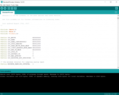
- Open Arduino and go to File>Examples>Firmata>Standard Firmata. Upload the sketch and check the Arduino port you are using.
TouchDesigner side
Firmata Palette
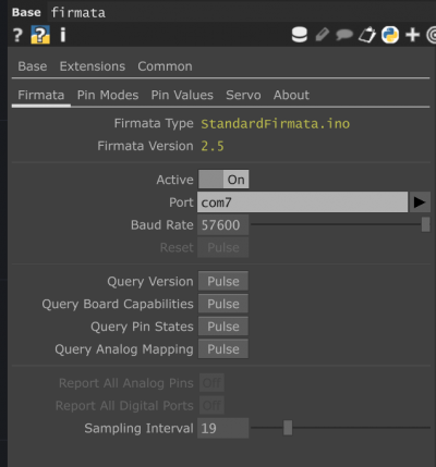
- Open a new TD file and drag into the Pane the Firmata palette (the palette menu is usually on the left side of your screen - you can find Firmata under Tools).
- In the menu select the Port and turn it to Active.
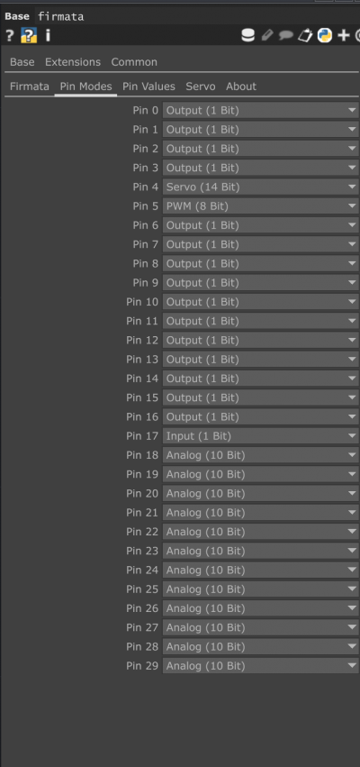
- Once it is active you can check the Pin Modes. You can find here all the options for your Pins. You can sent them as:
- Output
- Binary output: You can use for LEDs or in this example a Relay connected to a lamp
- PWM
- Pulse with modulation Pin: You can use to Fade Leds or for a Piezo
- Input
- Binary input: Receive signal from Pin
- Analog
- Analog Read: Gets reads from Analog Pins, you can use it to get simple sensor data
- Servo
- To use to control Servo motors
- Output
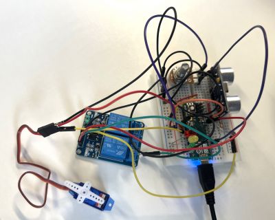
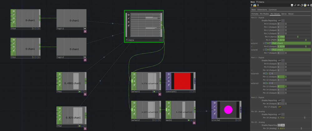
- You can select already the modes that you want, in my case I will have two Outputs to control two relays, a PWM to fade a LED, a Servo and two Analog to read an LDR and a potentiometer. Make sure you select the pin you have on the board. The Digital Pins follow the same number and the Analog chance accordingly to the board. In my case I am using an Arduino Micro and A0 and A1 are Pin 18 and 19 respectively.
- In the Firmata menu go now to Pin Values. Here you can set the values. They can be static or you can connect them to CHOPs. In this example I made a series of LFOs with different wave forms, binary pulses to control the relay, a gaussian and a ramp for the Servo and the fading LEDs. For in the inputs I am using a Select CHOP and a Math CHOP to re-adjust the values to be send to control TOPS.
