Difference between revisions of "Sensing and making with Arduino"
(Created page with "Sensing and Making with Arduino ==Building a interactive system== how is it made of - microcontroller and sensors physical computing ==What is Arduino== ===What can I do w...") |
|||
| (78 intermediate revisions by the same user not shown) | |||
| Line 1: | Line 1: | ||
| − | + | [[File:Sensingandmaking.png|500px|thumb]] | |
| + | ==Some examples to start== | ||
| + | Microcontrollers like Arduino are involved in lots of works. Here are some examples: | ||
| + | *[http://vtol.cc/filter/works/antenna Mom, I hit a man - vtol] | ||
| + | *[http://katihyyppa.com/as-light-goes-by/ As light goes by - Kati Hyyppa] | ||
| + | *[https://vimeo.com/236594080 Instant messanging - ECAL/Elise Migraine] | ||
| + | *[https://www.niklasroy.com/project/88/my-little-piece-of-privacy Niklas Roy A piece of privacy] | ||
| + | *[https://nathalie-gebert.com/symbiotic-transmitter.html Symbiotic Transmitter - Nathalie Gebert] | ||
| + | *[https://instrumentinventors.org/instructions3/ Matteo Marangoni & Dieter Vandoren - Komorebi] | ||
| + | *[https://v2.nl/works/lux-sonet-in-tenebris Lux Sonet In tenebris - Ennio Bertrand] | ||
| + | *[https://www.ronaldvandermeijs.nl/Time-capsule-of-life-2-0 Time capsule of life - Ronald van der Meijs] | ||
| + | *[https://interactionstation.wdka.hro.nl/wiki/Make_a_drawing_machine_and_a_Grabber_robot_with_Arduino Arduino Drawing Machine] | ||
==Building a interactive system== | ==Building a interactive system== | ||
| − | how is it | + | The projects we just saw deal with a discipline that we call <code>Physical Computing</code>. |
| − | + | ||
| + | <u>Physical computing involves interactive systems that can sense and respond to the world around them.</u> | ||
| + | In physical computing, we typically use a microcontroller that can sense the environment through sensors and use this data to trigger and control various applications such as motors, lights, sound, and so on. | ||
| + | |||
| + | [[File:Physical computing.png|500px|frameless]] | ||
| + | |||
| + | Let's see in detail how this works with a real example. Let's say we want to turn on a light when the room gets dark. | ||
| + | What we will need is a system that: | ||
| + | |||
| + | ↪Senses the light levels of the room and sends this information to a computer | ||
| + | |||
| + | ↪The computer can interpret this information. If the light is within a certain range that we consider darkness it will send a signal to an led to turn on | ||
| + | |||
| + | ↪LED will interpret this signal and light up | ||
| + | |||
| + | |||
| + | [[File:Artboard 1-100.jpg|1000px|frameless]] | ||
| + | |||
==What is Arduino== | ==What is Arduino== | ||
| − | ===What | + | [[About_Arduino|Arduino]] is a microcontroller, a type of device, like a small computer, designed to execute simple tasks. |
| − | + | Arduino is used by a wide for building digital devices and interactive objects that can sense and control the physical world. | |
| + | |||
| + | In essence Arduino is ''just another'' MicroController development board. The main purpose of such a MicroController development board is to make it easy for developers to evaluate the functions of, or create a quick prototype with, a certain type of MicroController. | ||
| + | MicroController come in al sorts of tastes and sizes hence there are many different flavours of MicroController development boards as well (ESP32, Teensy boards and so on). | ||
| + | |||
| + | ====What makes an Arduino?==== | ||
| + | Arduino is composed of two major parts: the Arduino board, which is the piece of hardware you work on when you build your objects; and the Arduino IDE, the piece of software you run on your computer. You use the IDE to create a sketch (a little computer program) that you upload to the Arduino board. The sketch tells the board what to do. | ||
| + | |||
| + | <br> | ||
| + | [[File:Uno_board.png|400px|The Arduino board]] | ||
| + | [[File:ide.png|400px|The Arduino IDE]] | ||
| + | <br> | ||
| + | |||
| + | ===Understanding the hardware=== | ||
| + | |||
| + | The Arduino board (and microcontrollers in general) are based on a simple input/output (I/O) logic. On the board you can see a series a '''pins''', which are the places where you connect your external components (like LEDS, sensors and so on) through wires.They usually have black plastic ‘headers’ that allow you to just plug a wire right into the board. <br> | ||
| + | |||
| + | The Arduino has different kinds of pins, each of which is labeled on the board and used for different functions. | ||
| + | '''Analog Input Pins''' ( we have six of them in the Uno): The area of pins under the ‘Analog In’ label (A0 through A5 on the UNO) are Analog In pins. These pins can read the signal from an analog sensor (like a temperature sensor) and convert it into a digital value that we can read. | ||
| − | == | + | '''Digital Input/Output Pins''' (seven on the Uno): Across from the analog pins are the digital pins (0 through 13 on the UNO). These pins can be used for both digital ''input'' (like telling if a button is pushed) and digital ''output'' (like powering an LED). |
| − | === | + | |
| + | [[File:Board_layout.PNG | 500 px]] | ||
| + | [[File:Arduino-uno.png| 500px]] | ||
| + | |||
| + | =First things first: Let's blink a LED!= | ||
| + | ===The LED=== | ||
| + | What is an LED?<br> | ||
| + | LED is short for light emitting diode, is a semiconductor device that emits light when an electric current is passed through it. Light is produced when the particles that carry the current (electrons and holes) combine together within the semiconductor material.<br> | ||
| + | LEDs come in different colors. Different semiconductor materials with different bandgaps (separation of the bands containing electrons and holes) produce different colors of light.<br> | ||
| + | [[File:Anodecathode.jpeg|600px]][[File:Battery_led.gif|200px]] | ||
| + | <br> | ||
| + | In an LED, energy flows in one direction, generating the luminous effect at the top, where the semiconductor is. | ||
| + | LEDs have two legs, corresponding to the positive and negative side, also known as Anode and Cathode. These can be distinguished because the positive leg, the Anode, is longer than the other one. If we connect these two poles to a battery, the LED will turn on. <br> | ||
| + | ===Connecting the LED to Arduino=== | ||
| + | Now we are going to connect Arduino to an LED. You will need: | ||
| + | <div style="font-family:monospace"> | ||
| + | * Arduino board | ||
| + | * a [[Breadboard|breadboard]] | ||
| + | * a 220 ohm [[BASIC_ELECTRONICS_-_Useful_and_fun_info#RESISTORS|resistor]] | ||
| + | * an LED | ||
| + | * jumper wires | ||
| + | </div> | ||
| + | [[File:Led.png|400px]] | ||
| + | <br> | ||
| + | Connect the Pins following the scheme: | ||
| + | |||
| + | *'''Anode(+)''' of the LED (the longer leg) to '''Digital pin 13'''; | ||
| + | *'''Cathode(-)''' of the LED (the shorter leg) to '''Ground(GND)'''; | ||
| + | |||
| + | You can connect this directly to the Ground Pin or you can connect it to any point the negative rail of the breadboard. This one that needs to be connected to the Ground pin. This last option is preferable in case you want to connect other LEDS or components that also need to be connected to the Ground pin. | ||
| + | </div> | ||
| + | |||
| + | ===Programming the LED=== | ||
| + | Now we are going to program the board to control the LED.To program your board you can use [https://www.arduino.cc/en/software Arduino's own software] that allows use to write code and upload it on the board.<br> | ||
| + | '''+ Open the Arduino software'''<br> | ||
| + | You can open the '''Arduino IDE''' software on the computer. This is already installed in WH.02.108 and most of the computers at the Interaction Station. If you want you can also use it on your laptop, you can install it thought | ||
| + | [https://www.arduino.cc/en/software this link]. <br> | ||
| + | It should look like this: <br> | ||
| + | [[File:Ide_first.png|600px]]<br> | ||
| + | '''+ Connect the board'''<br> | ||
| + | You can now connect the board to the computer: this will enable us to upload the sketch as well as to power the board. | ||
| + | If the software found your board your will see it on the bottom right corner. If not, it will show '''[not connected]'''. | ||
| + | To make select the board and the port you can go to '''Tools>Board''' and select your Arduino model, in our case is the Arduino Uno. To check if the right port is selected you can go to '''Tools>Port''' and select it. Often the software recognises it already and puts the board name between () after the port name. <br> | ||
| + | In the new version of Arduino you can see board and port directly on your sketch window.<br> | ||
| + | |||
| + | <br> | ||
| + | [[File:Ide_board.png|600px]]<br> | ||
| + | ====Turn on the LED==== | ||
| + | Open a new sketch | ||
| + | <syntaxhighlight lang="c"> | ||
| + | void setup() { | ||
| + | // put your setup code here, to run once: | ||
| + | pinMode(13, OUTPUT); | ||
| + | digitalWrite(13, HIGH); // turn LED on (output 5V) | ||
| + | } | ||
| + | |||
| + | void loop() { | ||
| + | // put your main code here, to run repeatedly: | ||
| + | |||
| + | } | ||
| + | </syntaxhighlight> | ||
| + | |||
| + | ====Blinking LED==== | ||
| + | <syntaxhighlight lang="c"> | ||
| + | void setup() { | ||
| + | // put your setup code here, to run once: | ||
| + | pinMode(13, OUTPUT); | ||
| + | } | ||
| + | |||
| + | void loop() { | ||
| + | // put your main code here, to run repeatedly: | ||
| + | digitalWrite(13, HIGH); | ||
| + | delay(500); | ||
| + | digitalWrite(13, LOW); | ||
| + | delay(500); | ||
| + | } | ||
| + | </syntaxhighlight> | ||
| + | <div style="font-family:monospace;"> | ||
| + | <span style="color:red;">'''!!!!Note:'''</span><br> | ||
| + | The [https://reference.arduino.cc/reference/en/language/functions/time/delay/ delay()] function pauses the program for an amount of time expressed in milliseconds. | ||
| + | For reference, 1000 milliseconds = 1 second. | ||
| + | </div> | ||
| + | |||
| + | ====Use a const==== | ||
| + | <syntaxhighlight lang="c"> | ||
| + | const int led = 13; | ||
| + | |||
| + | void setup() { | ||
| + | pinMode(led, OUTPUT); | ||
| + | } | ||
| + | |||
| + | void loop() { | ||
| + | digitalWrite(led, HIGH); // turn the LED on (HIGH is the voltage level) | ||
| + | delay(1000); // wait for a second | ||
| + | digitalWrite(led, LOW); // turn the LED off by making the voltage LOW | ||
| + | delay(1000); // wait for a second | ||
| + | } | ||
| + | </syntaxhighlight> | ||
=Project 1: Interactive light= | =Project 1: Interactive light= | ||
| − | + | We are gonna start with our first Interactive project. We will use a light sensor to measure the light level of the room and turn on our led when the room gets dark. | |
| − | + | ==Connect a light sensor== | |
| − | |||
| − | |||
| − | |||
| − | == | ||
===What is a light sensor=== | ===What is a light sensor=== | ||
| + | [[File:LDR.png|300px]]<br> | ||
| + | An LDR(=Light dependent resistor) is a sensor (or more properly a resistor) that is able to detect light levels. | ||
| + | =====How does it work?===== | ||
| + | Check this video: https://www.youtube.com/watch?v=u9Riurh4y9U <br> | ||
| + | Basically a LDR is a resistor whose resistance value is not fixed, instead its resistance decreases as the light intensity increases. This happens because the semi-conductive material os the resistor contains photosensitive cadmium sulphide. <br> | ||
| + | The LDR gives out an analog voltage when connected to VCC (5V), which varies in magnitude in direct proportion to the input light intensity on it. That is, the greater the intensity of light, the greater the corresponding voltage from the LDR will be. Since the LDR gives out an analog voltage, it is connected to the analog input pin on the Arduino. The Arduino, with its built-in ADC (analog-to-digital converter), then converts the analog voltage (from 0-5V) into a digital value in the range of (0-1023). | ||
====Wiring==== | ====Wiring==== | ||
| + | [[File:Led+ldr.png|400px|frameless]] | ||
| + | *Place the LDR on the breadboard | ||
| + | *Connect one leg of the LDR to 5v on Arduino | ||
| + | *Connect the other leg of the LDR to A0 on Arduino | ||
| + | *Connect the same leg to GND by putting a 10k Ohm resistor in between | ||
| + | |||
====Programming==== | ====Programming==== | ||
| + | =====Read the values from the light sensor===== | ||
| + | Open the Serial monitor: Go to <code>Tools>Serial Monitor</code> | ||
| + | |||
| + | You will see it appearing underneath your code in your sketch file. | ||
| + | <syntaxhighlight lang="c"> | ||
| + | const int led = 13; | ||
| + | const int ldr = A0; | ||
| + | |||
| + | void setup() { | ||
| + | pinMode(led, OUTPUT); | ||
| + | pinMode(ldr, INPUT); | ||
| + | Serial.begin(9600); | ||
| + | } | ||
| + | |||
| + | |||
| + | void loop() { | ||
| + | int ldrState = analogRead(ldr); | ||
| + | Serial.println(ldrState); | ||
| + | } | ||
| + | </syntaxhighlight> | ||
| + | You should see numbers appearing in your Serial Monitor: | ||
| + | |||
| + | [[File:Serialmonitor.png|500px|frameless]] | ||
| + | =====Make the light react to the ldr===== | ||
| + | <syntaxhighlight lang="c"> | ||
| + | const int led = 13; | ||
| + | const int ldr = A0; | ||
| + | |||
| + | void setup() { | ||
| + | pinMode(led, OUTPUT); | ||
| + | pinMode(ldr, INPUT); | ||
| + | Serial.begin(9600); | ||
| + | } | ||
| + | |||
| + | void loop() { | ||
| + | int ldrState = analogRead(ldr); | ||
| + | Serial.println(ldrState); | ||
| + | |||
| + | if (ldrState<500){ | ||
| + | digitalWrite(led,HIGH); | ||
| + | } | ||
| + | else{ | ||
| + | digitalWrite(led,LOW); | ||
| + | } | ||
| + | } | ||
| + | </syntaxhighlight> | ||
=Project 2: Distance detector= | =Project 2: Distance detector= | ||
| − | + | This time we are going to work with a motor and a distance sensor. We will make the motor wave a hand when someone gets close. | |
==Connect Arduino to Servo motor== | ==Connect Arduino to Servo motor== | ||
===Servo Motor=== | ===Servo Motor=== | ||
| + | [[File:Servo.jpg|500px|frameless]] | ||
| + | |||
| + | A Servo motor is a type of electrical motor that is used to give precise rotation directions. (Typically)It is able to move within an angle of 180.<br> | ||
| + | Here's a video that explain how it works: https://www.youtube.com/watch?v=tHOH-bYjR4k | ||
====Wiring==== | ====Wiring==== | ||
| + | [[File:Servooo.png|400px]] | ||
| + | |||
| + | Servo Brown wire ---> Arduino GND Pin | ||
| + | Servo Red wire ---> Arduino 5V Pin | ||
| + | Servo Orange wire ---> Arduino Digital Pin 6 | ||
| + | |||
====Programming==== | ====Programming==== | ||
| + | <syntaxhighlight lang="c"> | ||
| + | #include <Servo.h> | ||
| + | |||
| + | Servo myservo; // create Servo object to control a servo | ||
| + | |||
| + | void setup() { | ||
| + | myservo.attach(6); // attaches the servo on pin 9 to the Servo object | ||
| + | myservo.write (0); // tell servo to go to a angle 0 | ||
| + | } | ||
| + | |||
| + | void loop() { | ||
| + | |||
| + | myservo.write(90); // tell servo to go to a angle 90 | ||
| + | delay(500); | ||
| + | myservo.write (0); // tell servo to go to a angle 0 | ||
| + | delay(500); | ||
| + | |||
| + | } | ||
| + | </syntaxhighlight> | ||
| + | |||
| + | We have now a motion going to 0 to 90 degrees. We want to use this motion to simulate a hand waving. We can tape the motor to the desk to keep it steady and adjust the angles to make our waving happening. | ||
| + | |||
==Make it Interactive!: Connect a Ultrasonic sensor== | ==Make it Interactive!: Connect a Ultrasonic sensor== | ||
| + | Now that we have this motion we want to implement it with the distance sensor so that the hand will only wave if someone gets closer. | ||
| + | ==Connect the Ultrasonic Sensor== | ||
| + | ===Ultrasonic Sensor=== | ||
| + | [[File:Ultrasonic-sensor-how-it-works.gif]][[File:Ultrasonic1.gif]] | ||
| + | |||
| + | An ultrasonic sensor is an instrument that measures the distance to an object using ultrasonic sound waves. The sensor sends a wave that bounces back at it when it finds an obstacle on the way. It receives time data that can then be transformed into distance data. | ||
| + | These sensors are usually able to read distance up to 4 meters. | ||
| + | |||
====Wiring==== | ====Wiring==== | ||
| + | [[File:Servo+ultrasonic.png|400px]] | ||
| + | *Connect the 5V and GND of the Servo Motor to the + and - rails of the breadboard | ||
| + | *From the + and - rails connect to the 5V and GND Pin on the Arduino | ||
| + | *Place the Ultrasonic Sensor on the breadboard | ||
| + | *Connect VCC to the 5V rail of the breadboard | ||
| + | *Connect Trig to Pin 9 | ||
| + | *Connect Echo to Pin 10 | ||
| + | *Connect GND to the GND rail of the breadboard | ||
| + | |||
====Programming==== | ====Programming==== | ||
| + | =====Getting distance data===== | ||
| + | <syntaxhighlight lang="c"> | ||
| + | const int trigPin = 9; // Trigger pin of the HR-SR04 | ||
| + | const int echoPin = 10; // Echo pin of the HR-SR04 | ||
| + | |||
| + | long duration; | ||
| + | int distance; | ||
| + | |||
| + | void setup() { | ||
| + | pinMode(trigPin, OUTPUT); | ||
| + | pinMode(echoPin, INPUT); | ||
| + | Serial.begin(9600); | ||
| + | } | ||
| + | |||
| + | void loop() { | ||
| + | // Clear the trigPin | ||
| + | digitalWrite(trigPin, LOW); | ||
| + | delayMicroseconds(2); | ||
| + | // Sets the trigPin on HIGH state for 10 microseconds | ||
| + | digitalWrite(trigPin, HIGH); | ||
| + | delayMicroseconds(10); | ||
| + | digitalWrite(trigPin, LOW); | ||
| + | // Reads the echoPin, returns the sound wave travel time in microseconds | ||
| + | duration = pulseIn(echoPin, HIGH); | ||
| + | |||
| + | // Calculating the distance | ||
| + | distance = duration * 0.034 / 2; | ||
| + | |||
| + | //Prints the distance on the Serial Monitor | ||
| + | Serial.print("Distance: "); | ||
| + | Serial.println(distance); | ||
| + | } | ||
| + | </syntaxhighlight> | ||
| + | Check the readings of the distance on the Servo Motor. | ||
| + | |||
| + | =====Wave when someone gets closer===== | ||
| + | <syntaxhighlight lang="c"> | ||
| + | #include <Servo.h> | ||
| + | |||
| + | const int trigPin = 9; // Trigger pin of the HR-SR04 | ||
| + | const int echoPin = 10; // Echo pin of the HR-SR04 | ||
| + | const int servoPin = 6; // Servo motor pin | ||
| + | long duration; | ||
| + | int distance; | ||
| + | Servo myServo; | ||
| + | |||
| + | void setup() { | ||
| + | pinMode(trigPin, OUTPUT); | ||
| + | pinMode(echoPin, INPUT); | ||
| + | myServo.attach(servoPin); | ||
| + | myServo.write(70); | ||
| + | Serial.begin(9600); | ||
| + | } | ||
| + | |||
| + | void loop() { | ||
| + | // Clear the trigPin | ||
| + | digitalWrite(trigPin, LOW); | ||
| + | delayMicroseconds(2); | ||
| + | |||
| + | // Sets the trigPin on HIGH state for 10 microseconds | ||
| + | digitalWrite(trigPin, HIGH); | ||
| + | delayMicroseconds(10); | ||
| + | digitalWrite(trigPin, LOW); | ||
| + | |||
| + | // Reads the echoPin, returns the sound wave travel time in microseconds | ||
| + | duration = pulseIn(echoPin, HIGH); | ||
| + | |||
| + | // Calculating the distance | ||
| + | distance = duration * 0.034 / 2; | ||
| + | |||
| + | // Prints the distance on the Serial Monitor | ||
| + | //Serial.print("Distance: "); | ||
| + | //Serial.println(distance); | ||
| + | |||
| + | // If an object is closer than 20cm, activate the servo | ||
| + | if (distance < 20) { | ||
| + | //wave twice | ||
| + | for (int i=0;i<2;i++){ | ||
| + | myServo.write(70); | ||
| + | Serial.println("servo on 70"); | ||
| + | delay(300); | ||
| + | myServo.write(130); | ||
| + | Serial.println("servo on 130"); | ||
| + | delay(300); | ||
| + | } | ||
| + | |||
| + | //hand goes back down | ||
| + | myServo.write(70); | ||
| + | delay(800); | ||
| + | } | ||
| + | } | ||
| + | </syntaxhighlight> | ||
| + | |||
| + | [[Category:Station Skills]] | ||
Latest revision as of 12:13, 18 November 2024
Some examples to start
Microcontrollers like Arduino are involved in lots of works. Here are some examples:
- Mom, I hit a man - vtol
- As light goes by - Kati Hyyppa
- Instant messanging - ECAL/Elise Migraine
- Niklas Roy A piece of privacy
- Symbiotic Transmitter - Nathalie Gebert
- Matteo Marangoni & Dieter Vandoren - Komorebi
- Lux Sonet In tenebris - Ennio Bertrand
- Time capsule of life - Ronald van der Meijs
- Arduino Drawing Machine
Building a interactive system
The projects we just saw deal with a discipline that we call Physical Computing.
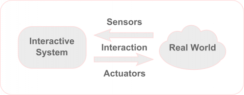
Physical computing involves interactive systems that can sense and respond to the world around them. In physical computing, we typically use a microcontroller that can sense the environment through sensors and use this data to trigger and control various applications such as motors, lights, sound, and so on.
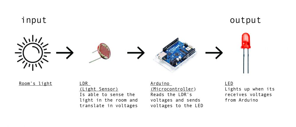
Let's see in detail how this works with a real example. Let's say we want to turn on a light when the room gets dark. What we will need is a system that:
↪Senses the light levels of the room and sends this information to a computer
↪The computer can interpret this information. If the light is within a certain range that we consider darkness it will send a signal to an led to turn on
↪LED will interpret this signal and light up
What is Arduino
Arduino is a microcontroller, a type of device, like a small computer, designed to execute simple tasks. Arduino is used by a wide for building digital devices and interactive objects that can sense and control the physical world.
In essence Arduino is just another MicroController development board. The main purpose of such a MicroController development board is to make it easy for developers to evaluate the functions of, or create a quick prototype with, a certain type of MicroController. MicroController come in al sorts of tastes and sizes hence there are many different flavours of MicroController development boards as well (ESP32, Teensy boards and so on).
What makes an Arduino?
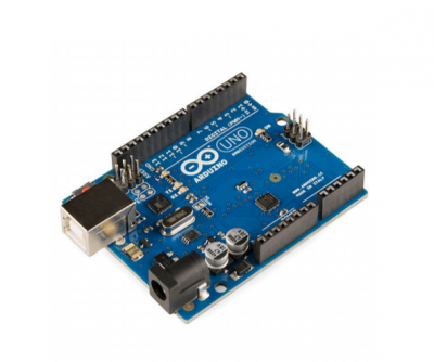
Arduino is composed of two major parts: the Arduino board, which is the piece of hardware you work on when you build your objects; and the Arduino IDE, the piece of software you run on your computer. You use the IDE to create a sketch (a little computer program) that you upload to the Arduino board. The sketch tells the board what to do.
Understanding the hardware
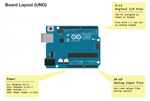
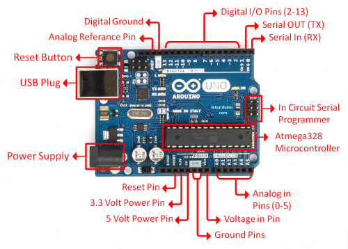
The Arduino board (and microcontrollers in general) are based on a simple input/output (I/O) logic. On the board you can see a series a pins, which are the places where you connect your external components (like LEDS, sensors and so on) through wires.They usually have black plastic ‘headers’ that allow you to just plug a wire right into the board.
The Arduino has different kinds of pins, each of which is labeled on the board and used for different functions.
Analog Input Pins ( we have six of them in the Uno): The area of pins under the ‘Analog In’ label (A0 through A5 on the UNO) are Analog In pins. These pins can read the signal from an analog sensor (like a temperature sensor) and convert it into a digital value that we can read.
Digital Input/Output Pins (seven on the Uno): Across from the analog pins are the digital pins (0 through 13 on the UNO). These pins can be used for both digital input (like telling if a button is pushed) and digital output (like powering an LED).
First things first: Let's blink a LED!
The LED
What is an LED?
LED is short for light emitting diode, is a semiconductor device that emits light when an electric current is passed through it. Light is produced when the particles that carry the current (electrons and holes) combine together within the semiconductor material.
LEDs come in different colors. Different semiconductor materials with different bandgaps (separation of the bands containing electrons and holes) produce different colors of light.
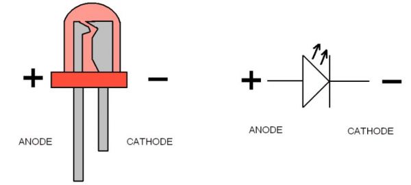
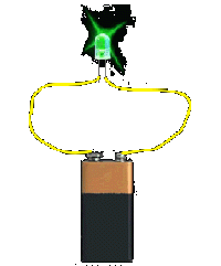
In an LED, energy flows in one direction, generating the luminous effect at the top, where the semiconductor is.
LEDs have two legs, corresponding to the positive and negative side, also known as Anode and Cathode. These can be distinguished because the positive leg, the Anode, is longer than the other one. If we connect these two poles to a battery, the LED will turn on.
Connecting the LED to Arduino
Now we are going to connect Arduino to an LED. You will need:
- Arduino board
- a breadboard
- a 220 ohm resistor
- an LED
- jumper wires
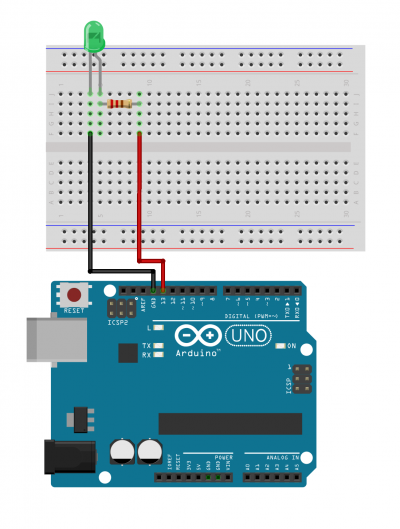
Connect the Pins following the scheme:
*Anode(+) of the LED (the longer leg) to Digital pin 13;
*Cathode(-) of the LED (the shorter leg) to Ground(GND);
You can connect this directly to the Ground Pin or you can connect it to any point the negative rail of the breadboard. This one that needs to be connected to the Ground pin. This last option is preferable in case you want to connect other LEDS or components that also need to be connected to the Ground pin.
Programming the LED
Now we are going to program the board to control the LED.To program your board you can use Arduino's own software that allows use to write code and upload it on the board.
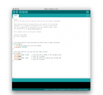
+ Open the Arduino software
You can open the Arduino IDE software on the computer. This is already installed in WH.02.108 and most of the computers at the Interaction Station. If you want you can also use it on your laptop, you can install it thought
this link.
It should look like this:
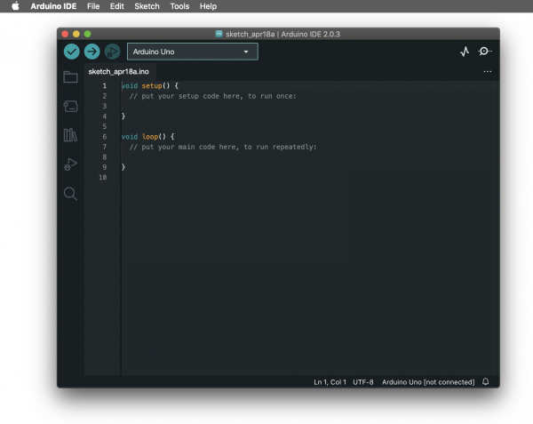
+ Connect the board
You can now connect the board to the computer: this will enable us to upload the sketch as well as to power the board.
If the software found your board your will see it on the bottom right corner. If not, it will show [not connected].
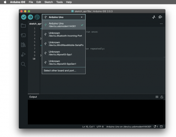
To make select the board and the port you can go to Tools>Board and select your Arduino model, in our case is the Arduino Uno. To check if the right port is selected you can go to Tools>Port and select it. Often the software recognises it already and puts the board name between () after the port name.
In the new version of Arduino you can see board and port directly on your sketch window.
Turn on the LED
Open a new sketch
void setup() {
  // put your setup code here, to run once:
  pinMode(13, OUTPUT);
  digitalWrite(13, HIGH); // turn LED on (output 5V)
}

void loop() {
  // put your main code here, to run repeatedly:

}
Blinking LED
void setup() {
  // put your setup code here, to run once:
  pinMode(13, OUTPUT);
}

void loop() {
  // put your main code here, to run repeatedly:
    digitalWrite(13, HIGH);
    delay(500);
    digitalWrite(13, LOW);
    delay(500);
}
!!!!Note:
The delay() function pauses the program for an amount of time expressed in milliseconds.
For reference, 1000 milliseconds = 1 second.
Use a const
const int led = 13;

void setup() {
  pinMode(led, OUTPUT);
}

void loop() {
  digitalWrite(led, HIGH);  // turn the LED on (HIGH is the voltage level)
  delay(1000);                      // wait for a second
  digitalWrite(led, LOW);   // turn the LED off by making the voltage LOW
  delay(1000);                      // wait for a second
}
Project 1: Interactive light
We are gonna start with our first Interactive project. We will use a light sensor to measure the light level of the room and turn on our led when the room gets dark.
Connect a light sensor
What is a light sensor
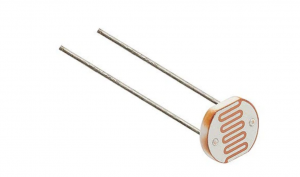
An LDR(=Light dependent resistor) is a sensor (or more properly a resistor) that is able to detect light levels.
How does it work?
Check this video: https://www.youtube.com/watch?v=u9Riurh4y9U
Basically a LDR is a resistor whose resistance value is not fixed, instead its resistance decreases as the light intensity increases. This happens because the semi-conductive material os the resistor contains photosensitive cadmium sulphide.
The LDR gives out an analog voltage when connected to VCC (5V), which varies in magnitude in direct proportion to the input light intensity on it. That is, the greater the intensity of light, the greater the corresponding voltage from the LDR will be. Since the LDR gives out an analog voltage, it is connected to the analog input pin on the Arduino. The Arduino, with its built-in ADC (analog-to-digital converter), then converts the analog voltage (from 0-5V) into a digital value in the range of (0-1023).
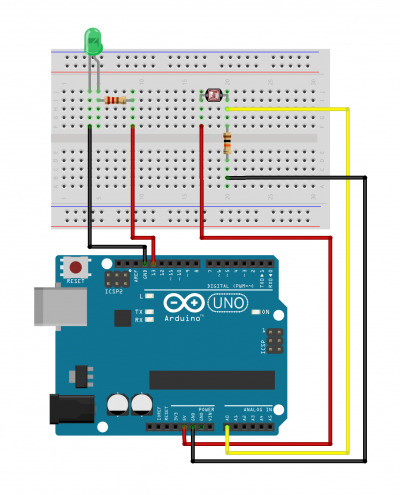
Wiring
*Place the LDR on the breadboard
*Connect one leg of the LDR to 5v on Arduino
*Connect the other leg of the LDR to A0 on Arduino
*Connect the same leg to GND by putting a 10k Ohm resistor in between
Programming
Read the values from the light sensor
Open the Serial monitor: Go to Tools>Serial Monitor
You will see it appearing underneath your code in your sketch file.
const int led = 13;
const int ldr = A0;

void setup() {
  pinMode(led, OUTPUT);
  pinMode(ldr, INPUT);
  Serial.begin(9600);
}


void loop() {
  int ldrState = analogRead(ldr);
  Serial.println(ldrState);
}
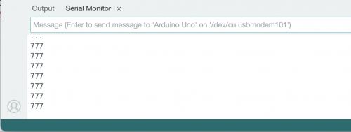
You should see numbers appearing in your Serial Monitor:
Make the light react to the ldr
const int led = 13;
const int ldr = A0;

void setup() {
  pinMode(led, OUTPUT);
  pinMode(ldr, INPUT);
  Serial.begin(9600);
}

void loop() {
  int ldrState = analogRead(ldr);
  Serial.println(ldrState);

  if (ldrState<500){
    digitalWrite(led,HIGH);
  }
  else{
    digitalWrite(led,LOW);
  }
}
Project 2: Distance detector
This time we are going to work with a motor and a distance sensor. We will make the motor wave a hand when someone gets close.
Connect Arduino to Servo motor
Servo Motor
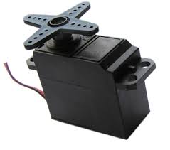
A Servo motor is a type of electrical motor that is used to give precise rotation directions. (Typically)It is able to move within an angle of 180.
Here's a video that explain how it works: https://www.youtube.com/watch?v=tHOH-bYjR4k
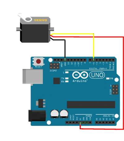
Wiring
Servo Brown wire ---> Arduino GND Pin
Servo Red wire ---> Arduino 5V Pin
Servo Orange wire ---> Arduino Digital Pin 6
Programming
#include <Servo.h>

Servo myservo;  // create Servo object to control a servo

void setup() {
  myservo.attach(6);  // attaches the servo on pin 9 to the Servo object
  myservo.write (0);  // tell servo to go to a angle 0
}

void loop() {

    myservo.write(90);   // tell servo to go to a angle 90
    delay(500);
    myservo.write (0);  // tell servo to go to a angle 0
    delay(500);

}
We have now a motion going to 0 to 90 degrees. We want to use this motion to simulate a hand waving. We can tape the motor to the desk to keep it steady and adjust the angles to make our waving happening.
Make it Interactive!: Connect a Ultrasonic sensor
Now that we have this motion we want to implement it with the distance sensor so that the hand will only wave if someone gets closer.
Connect the Ultrasonic Sensor
Ultrasonic Sensor
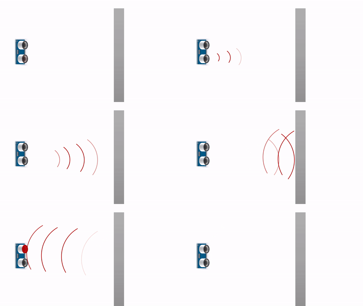
An ultrasonic sensor is an instrument that measures the distance to an object using ultrasonic sound waves. The sensor sends a wave that bounces back at it when it finds an obstacle on the way. It receives time data that can then be transformed into distance data. These sensors are usually able to read distance up to 4 meters.
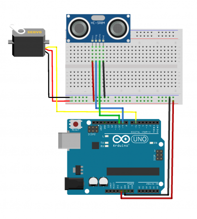
Wiring
*Connect the 5V and GND of the Servo Motor to the + and - rails of the breadboard
*From the + and - rails connect to the 5V and GND Pin on the Arduino
*Place the Ultrasonic Sensor on the breadboard
*Connect VCC to the 5V rail of the breadboard
*Connect Trig to Pin 9
*Connect Echo to Pin 10
*Connect GND to the GND rail of the breadboard
Programming
Getting distance data
const int trigPin = 9;    // Trigger pin of the HR-SR04
const int echoPin = 10;   // Echo pin of the HR-SR04

long duration;
int distance;

void setup() {
  pinMode(trigPin, OUTPUT);
  pinMode(echoPin, INPUT);
  Serial.begin(9600);
}

void loop() {
  // Clear the trigPin
  digitalWrite(trigPin, LOW);
  delayMicroseconds(2);
  // Sets the trigPin on HIGH state for 10 microseconds
  digitalWrite(trigPin, HIGH);
  delayMicroseconds(10);
  digitalWrite(trigPin, LOW);
  // Reads the echoPin, returns the sound wave travel time in microseconds
  duration = pulseIn(echoPin, HIGH);

  // Calculating the distance
  distance = duration * 0.034 / 2;

  //Prints the distance on the Serial Monitor
  Serial.print("Distance: ");
  Serial.println(distance);
}
Check the readings of the distance on the Servo Motor.
Wave when someone gets closer
#include <Servo.h>

const int trigPin = 9;    // Trigger pin of the HR-SR04
const int echoPin = 10;   // Echo pin of the HR-SR04
const int servoPin = 6;   // Servo motor pin
long duration;
int distance;
Servo myServo;

void setup() {
  pinMode(trigPin, OUTPUT);
  pinMode(echoPin, INPUT);
  myServo.attach(servoPin);
  myServo.write(70);
  Serial.begin(9600);
}

void loop() {
  // Clear the trigPin
  digitalWrite(trigPin, LOW);
  delayMicroseconds(2);

  // Sets the trigPin on HIGH state for 10 microseconds
  digitalWrite(trigPin, HIGH);
  delayMicroseconds(10);
  digitalWrite(trigPin, LOW);

  // Reads the echoPin, returns the sound wave travel time in microseconds
  duration = pulseIn(echoPin, HIGH);

  // Calculating the distance
  distance = duration * 0.034 / 2;

  // Prints the distance on the Serial Monitor
  //Serial.print("Distance: ");
  //Serial.println(distance);

  // If an object is closer than 20cm, activate the servo
  if (distance < 20) {
    //wave twice
    for (int i=0;i<2;i++){
      myServo.write(70);
      Serial.println("servo on 70");
      delay(300);
      myServo.write(130);
      Serial.println("servo on 130");
      delay(300);
    }

    //hand goes back down
    myServo.write(70);
    delay(800);
  }
}
