Difference between revisions of "Design-batteryholder"
| Line 37: | Line 37: | ||
If you start the simulation, it works! | If you start the simulation, it works! | ||
If you click on the LED in the second image, without the switch, you can get a comment, that there is something "wrong". | If you click on the LED in the second image, without the switch, you can get a comment, that there is something "wrong". | ||
| + | |||
| + | Now I would like to know if that is also true in "reality". So I have to make my circuit and measure. | ||
| + | (wait a moment, because "reality" costs time!) | ||
| + | |||
| + | ..... | ||
Revision as of 10:04, 9 April 2020
Zooming in on the components of the first example http://interactionstation.wdka.hro.nl/wiki/Mona-lisa
The battery holder.
First the boring part, how it works.....
The battery is for providing energy to your circuit.
Your circuit "works", so it consumes energy.
The battery....it seems so simple, you buy a battery. But there are so many batteries, which battery to buy?
let's keep this simpel: for a circuit with LED's , the most simple circuits you need a "coin-cell" battery of 3V.
The LED asks for a voltage that is near this value. There are different LED's, every color has it's own Voltage value.
Now you could and should ask: What is Voltage?
And this is a question which is not so easy to answer! Voltage is quite a complex notion and it takes time to explain, and even then......for instance:
https://www.youtube.com/watch?v=zYS9kdS56l8
https://www.youtube.com/watch?v=zqGvUbvVQXg
https://www.youtube.com/watch?v=F_vLWkkOETI
So let's do this in the practical way: we need a battery plus holder for a LED, we take the coin cell battery and holder and it "works" because it has nearly the right values.
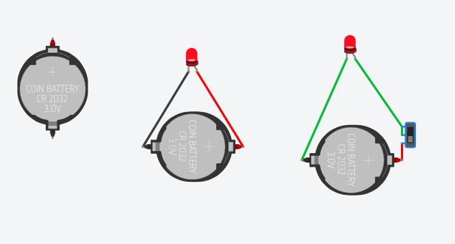
We can "get" this battery holder in Tinkercad:
 circuits form Tinkercad circuits form Tinkercad
|
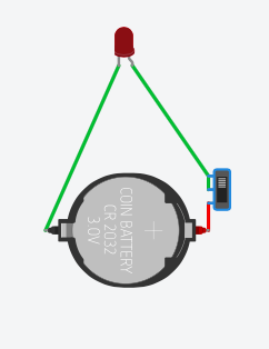
 the circuit with the switch can be switched off and on the circuit with the switch can be switched off and on
|
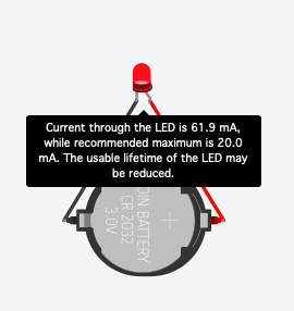
 Tinkercad tells you the LED gets too much current. Tinkercad tells you the LED gets too much current.
|
If you start the simulation, it works! If you click on the LED in the second image, without the switch, you can get a comment, that there is something "wrong".
Now I would like to know if that is also true in "reality". So I have to make my circuit and measure. (wait a moment, because "reality" costs time!)
.....