Difference between revisions of "Basic electronic components and sensors"
(Created page with "== Basic Components == file:BasicComponents.jpg === Resistors === file:Resistors.jpg As the name implies, resistors add resistance to the circuit and reduce the fl...") |
|||
| Line 146: | Line 146: | ||
An integrated circuit is an entire specialized circuit that has been miniaturized and fit onto one small chip with each leg of the chip connecting to a point within the circuit. These miniaturized circuits typically consist of components such as transistors, resistors, and diodes. | An integrated circuit is an entire specialized circuit that has been miniaturized and fit onto one small chip with each leg of the chip connecting to a point within the circuit. These miniaturized circuits typically consist of components such as transistors, resistors, and diodes. | ||
[[Integrated Circuits]] | [[Integrated Circuits]] | ||
| + | |||
| + | =='''Sensing'''== | ||
| + | |||
| + | we often construct our reality using our sensory experience: | ||
| + | |||
| + | our visual and sound come from our eyes and ears, we can feel the moisture level on our skins, we can feel the gravity and orientation thanks for our inner ear structures. | ||
| + | |||
| + | and now imagine all the sensory input can be converted into digits and feed to a computer, and the computer device can decide what to do(output) with the input data. | ||
| + | let's look back to Shannon-Weaver model of communication. | ||
| + | |||
| + | |||
| + | there is so many already made sensor module for Arduino. Many sensors can detect signals or pick up data beyond human senses. For example ultrasonic sensors. | ||
| + | Imagine we can use these sensor technologies to expend our senses and "reality". | ||
| + | |||
| + | Back to the Sensors: | ||
| + | In General, there are two types of sensors: analog and digital. | ||
| + | |||
| + | The analog sensor can detect a range of data. (for example from 0-1020) | ||
| + | |||
| + | The digital sensor can detect either 0 or 1.(or HIGHT /LOW). | ||
| + | |||
| + | for better understanding: the analog sensor is like a dimmer and the digital sensor is like a normal switch. | ||
| + | |||
| + | Here is a list of sensors and examples: | ||
| + | |||
| + | [['''Comment sensors:''']] | ||
| + | Don't need additional libraries, normally included in Arduino's example tutorials.<br> | ||
| + | Potential meters: [https://www.arduino.cc/en/Tutorial/AnalogReadSerial AnalogReadSerial] | ||
| + | Botton or switch: [https://www.arduino.cc/en/Tutorial/Button Button] | ||
| + | Ultrasonic sensor: [https://www.arduino.cc/en/Tutorial/Ping Ping] | ||
| + | Mic or piezo: [https://www.arduino.cc/en/Tutorial/Knock knock] | ||
| + | [https://www.arduino.cc/en/Tutorial/toneMultiple toneMultiple] | ||
| + | |||
| + | Flex & force sensor: [https://www.arduino.cc/en/Tutorial/toneKeyboard toneKeyboard] | ||
| + | LDR (Light Dependent Resistor): | ||
| + | [https://www.arduino.cc/en/Tutorial/Calibration Calibration] | ||
| + | [https://www.arduino.cc/en/Tutorial/tonePitchFollower tonePitchFollower] | ||
| + | |||
| + | [[ '''Advanced sensors:''']] | ||
| + | Need to install additional libraries.<br> | ||
| + | Capacitive Sensor-Analog : [https://learn.adafruit.com/adafruit-cap1188-breakout/using-with-arduino adafruit-cap1188-breakout] | ||
| + | Or [https://www.bareconductive.com/shop/touch-board/ touch-board] | ||
| + | Pulse sensor(heart rate): [https://pulsesensor.com/pages/installing-our-playground-for-pulsesensor-arduino pulsesensor] | ||
| + | UV sensor: [https://learn.adafruit.com/adafruit-si1145-breakout-board-uv-ir-visible-sensor/overview uv-index-sensor] | ||
| + | Gyroscope/acceleration meter:[https://learn.adafruit.com/adafruit-lsm9ds1-accelerometer-plus-gyro-plus-magnetometer-9-dof-breakout/arduino-code Gyroscope/acceleration] | ||
Revision as of 15:53, 4 April 2021
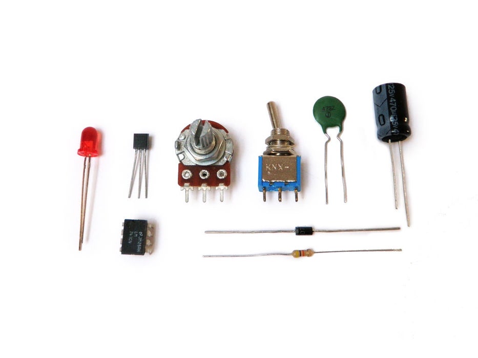
Basic Components
Resistors
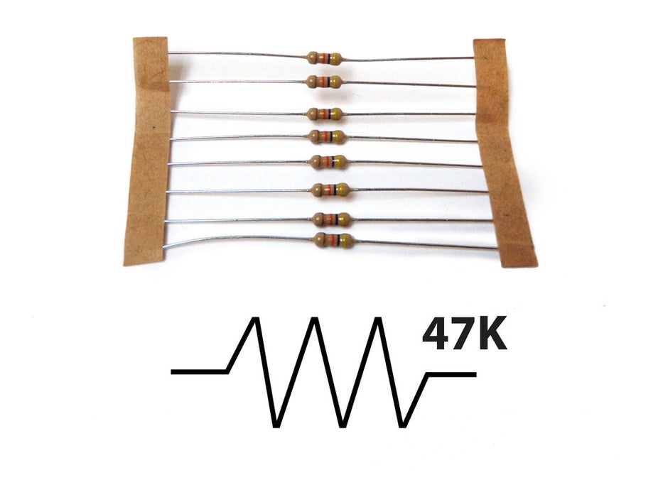
As the name implies, resistors add resistance to the circuit and reduce the flow of electrical current. It is represented in a circuit diagram as a pointy squiggle with a value next to it.
The different markings on the resistor represent different values of resistance. These values are measured in ohms.
Resistors also come with different wattage ratings. For most low-voltage DC circuits, 1/4 watt resistors should be suitable.
You read the values from left to right towards the (typically) gold band. The first two colors represent the resistor value, the third represents the multiplier, and the fourth (the gold band) represents the tolerance or precision of the component. You can tell the value of each color by looking at a resistor color value chart.
Or... to make your life easier, you could simply look up the values using a [graphical resistance calculator].
Anyhow... a resistor with the markings brown, black, orange, gold will translate as follows:
1 (brown) 0 (black) x 1,000 = 10,000 with a tolerance of +/- 5%
Any resistor of over 1000 ohms is typically shorted using the letter K. For instance, 1,000 would be 1K; 3,900, would translate to 3.9K; and 470,000 ohms would become 470K.
Values of ohms over a million are represented using the letter M. In this case, 1,000,000 ohms would become 1M.
Capacitors
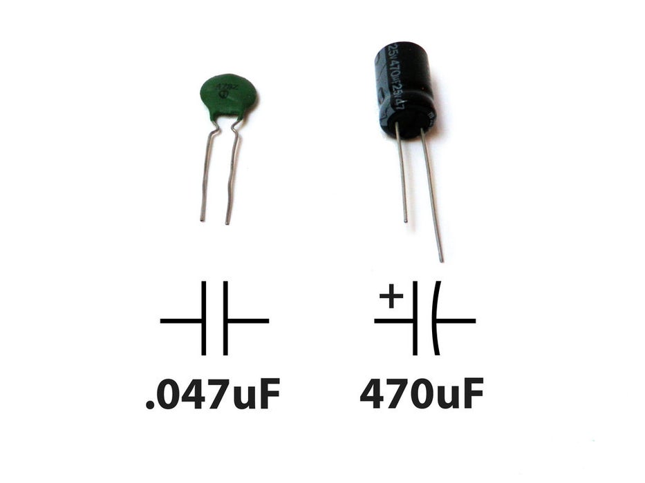
A capacitor is a component that stores electricity and then discharges it into the circuit when there is a drop in electricity. You can think of it as a water storage tank that releases water when there is a drought to ensure a steady stream.
for more info capacitors
Diodes
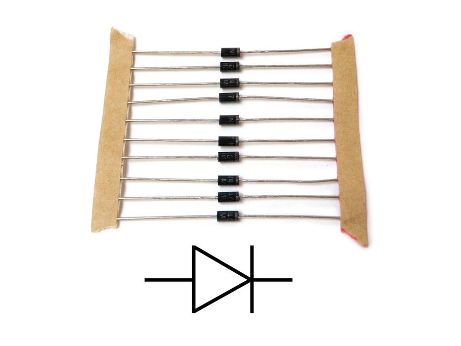
Diodes are components which are polarized. They only allow electrical current to pass through them in one direction. This is useful in that it can be placed in a circuit to prevent electricity from flowing in the wrong direction.
more info Diodes
Transistors
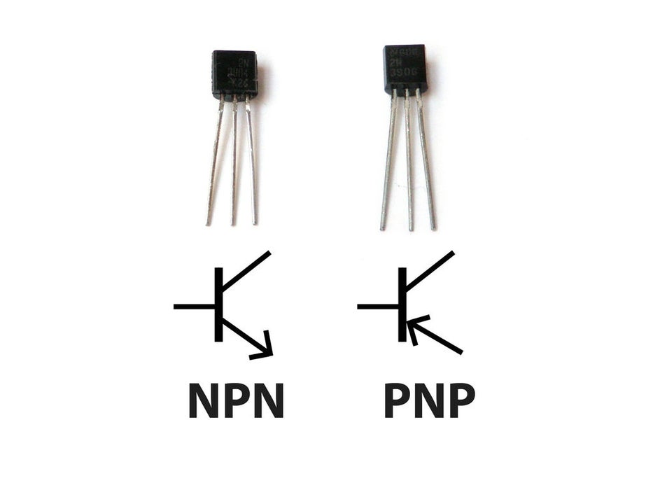
A transistor takes in a small electrical current at its base pin and amplifies it such that a much larger current can pass between its collector and emitter pins. The amount of current that passes between these two pins is proportional to the voltage being applied at the base pin.
more info Transistors
Potentiometers
Potentiometers are variable resistors. In plain English, they have some sort of knob or slider that you turn or push to change resistance in a circuit. If you have ever used a volume knob on a stereo or a sliding light dimmer, then you have used a potentiometer.
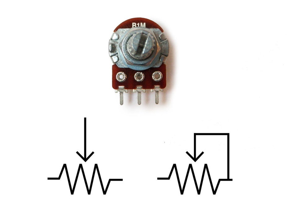
Potentiometers are measured in ohms like resistors, but rather than having color bands, they have their value rating written directly on them (i.e. "1M"). They are also marked with an "A" or a "B, " which indicated the type of response curve it has.
Potentiometers marked with a "B" have a linear response curve. This means that as you turn the knob, the resistance increases evenly (10, 20, 30, 40, 50, etc.). The potentiometers marked with an "A" have a logarithmic response curve. This means that as you turn the knob, the numbers increase logarithmically (1, 10, 100, 10,000 etc.)
Potentiometers have three legs as to create a voltage divider, which is basically two resistors in series. When two resistors are put in series, the point between them is a voltage that is a value somewhere between the source value and ground.
For instance, if you have two 10K resistors in series between power (5V) and ground (0V), the point where these two resistors meet will be half the power supply (2.5V) because both of the resistors have identical values. Assuming this middle point is actually the center pin of a potentiometer, as you turn the knob, the voltage on the middle pin will actually increase towards 5V or decrease toward 0V (depending which direction that you turn it). This is useful for adjusting the intensity of an electrical signal within a circuit (hence its use as a volume knob).
This is represented in a circuit as a resistor with an arrow pointing towards the middle of it.
If you only connect one of the outer pins and the center pin to the circuit, you are only changing the resistance within the circuit and not the voltage level on the middle pin. This too is a useful tool for circuit building because often you just want to change the resistance at a particular point and not create an adjustable voltage divider. This configuration is often represented in a circuit as a resistor with an arrow coming out of one side and looping back in to point towards the middle.
LEDs
LED stands for light emitting diode. It is basically a special type of diode that lights up when electricity passes through it. Like all diodes, the LED is polarized and electricity is only intended to pass through in one direction.
There are typically two indicators to let you know what direction electricity will pass through and LED. The first indicator that the LED will have a longer positive lead (anode) and a shorter ground lead (cathode). The other indicator is a flat notch on the side of the LED to indicate the positive (anode) lead. Keep in mind that not all LEDs have this indication notch (or that it is sometimes wrong).
Like all diodes, LEDs create a voltage drop in the circuit, but typically do not add much resistance. In order to prevent the circuit from shorting, you need to add a resistor in series. To figure out how large of a resistor you need for optimum intensity, you can use this online LED calculator to figure out how much resistance is needed for a single LED. It is often good practice to use a resistor that is slightly larger in the value than what is returned by [calculator].
Typically, the forward voltage of an LED is between 1.8 and 3.3 volts. It varies by the color of the LED. A red LED typically drops 1.8 volts. For most purposes, the exact value is not critical and you can use 2V for red, yellow and green, or 4V for blue and white LEDs.
The LED current must be less than the maximum permitted for your LED. For standard 5mm diameter LEDs the maximum current is usually 20mA, so 10mA or 15mA are suitable values for many circuits. The current must be in amps (A) for the calculation, to convert from mA to A divide the current in mA by 1000.
You may be tempted to wire LEDs in series, but keep in mind that each consecutive LED will result in a voltage drop until finally there is not enough power left to keep them lit. As such, it is ideal to light up multiple LEDs by wiring them in parallel. However, you need to make certain that all of the LEDs have the same power rating before you do this (different colors often are rated differently).
LEDs will show up in a schematic as a diode symbol with lightning bolts coming off of it, to indicate that it is a glowing diode.
Buttons and Switches
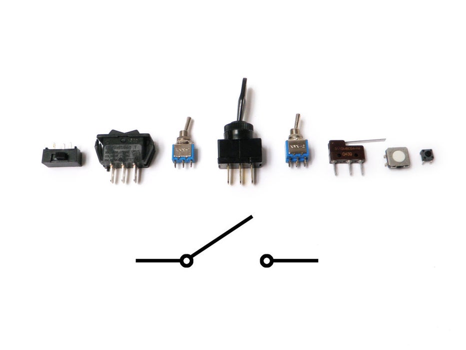
A switch is basically a mechanical device that creates a break in a circuit. When you activate the switch, it opens or closes the circuit. This is dependent on the type of switch it is.
Normally open (N.O.) switches close the circuit when activated.
Normally closed (N.C.) switches open the circuit when activated.
As switches get more complex they can both open one connection and close another when activated. This type of switch is a single-pole double-throw switch (SPDT).
If you were to combine two SPDT switches into one single switch, it would be called a double-pole double-throw switch (DPDT). This would break two separate circuits and open two other circuits, every time the switch was activated.
Batteries and Power Supply
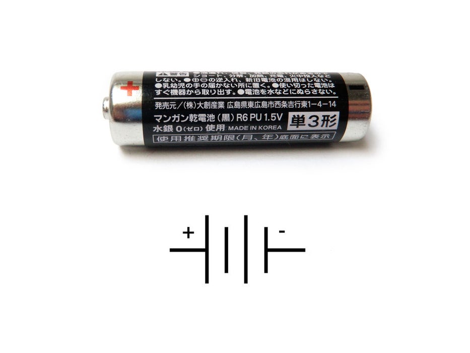
A battery is a container which converts chemical energy into electricity. To over-simplify the matter, you can say that it "stores power."
By placing batteries in series you are adding the voltage of each consecutive battery, but the current stays the same. For instance, a AA-battery is 1.5V. If you put 3 in series, it would add up to 4.5V. If you were to add a fourth in series, it would then become 6V.
By placing batteries in parallel the voltage remains the same, but the amount of current available doubles. This is done much less frequently than placing batteries in series, and is usually only necessary when the circuit requires more current than a single series of batteries can offer.
It is recommended that you get a range of AA battery holders. For instance, I would get an assortment that holds 1, 2, 3, 4, and 8 AA batteries.
Breadboards
OK, first, what's with the name....bread board? Bread, like in food?
Well yes, kind of.
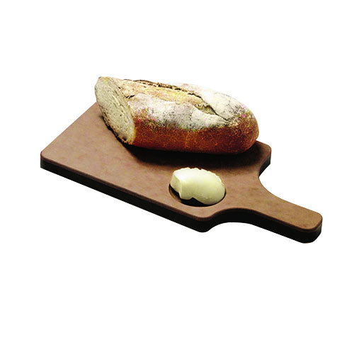
This terminology goes way back in the days.
Generally, you would mount electronic components to a piece of wood (the actual "breadboard"), and do all the wiring with point-point wire and the components just hanging between the various devices.
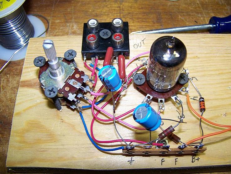
The story goes that an engineer had an idea for a vacuum tube device late one night. Looking around the house, the only base for his prototype that he found was indeed his wife's breadboard, from the breadbox.
A video by the Make magazine people
Ok, but why do we need to breadboard?
Well, they are useful for making temporary circuits and prototyping, and they require absolutely no soldering.
Prototyping is the process of testing out an idea by creating a preliminary model from which other forms are developed or copied,
and it is one of the most common uses for breadboards.
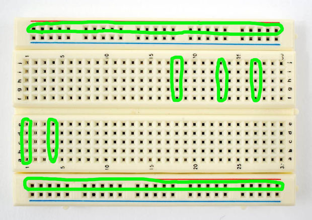
The best way to explain how a breadboard works is to take it apart and see what’s inside.
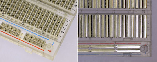
connections lines are connected like this
Integrated Circuits
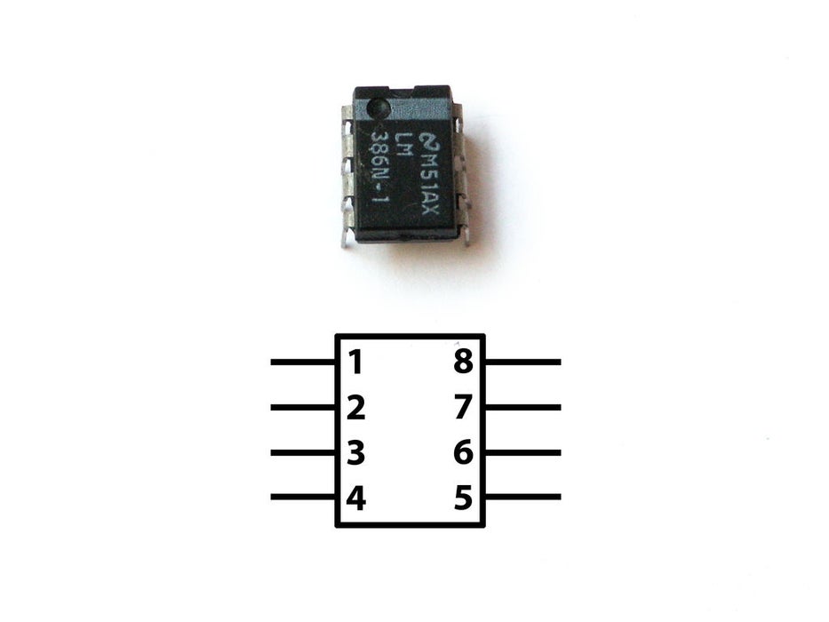
An integrated circuit is an entire specialized circuit that has been miniaturized and fit onto one small chip with each leg of the chip connecting to a point within the circuit. These miniaturized circuits typically consist of components such as transistors, resistors, and diodes. Integrated Circuits
Sensing
we often construct our reality using our sensory experience:
our visual and sound come from our eyes and ears, we can feel the moisture level on our skins, we can feel the gravity and orientation thanks for our inner ear structures.
and now imagine all the sensory input can be converted into digits and feed to a computer, and the computer device can decide what to do(output) with the input data. let's look back to Shannon-Weaver model of communication.
there is so many already made sensor module for Arduino. Many sensors can detect signals or pick up data beyond human senses. For example ultrasonic sensors.
Imagine we can use these sensor technologies to expend our senses and "reality".
Back to the Sensors: In General, there are two types of sensors: analog and digital.
The analog sensor can detect a range of data. (for example from 0-1020)
The digital sensor can detect either 0 or 1.(or HIGHT /LOW).
for better understanding: the analog sensor is like a dimmer and the digital sensor is like a normal switch.
Here is a list of sensors and examples:
'''Comment sensors:'''
 Don't need additional libraries, normally included in Arduino's example tutorials.

 Potential meters: AnalogReadSerial
 Botton or switch: Button
 Ultrasonic sensor: Ping
 Mic or piezo: knock
               toneMultiple
 Flex & force sensor: toneKeyboard
 LDR (Light Dependent Resistor):
 Calibration
 tonePitchFollower
 Need to install additional libraries.

 Capacitive Sensor-Analog : adafruit-cap1188-breakout
 Or touch-board
 Pulse sensor(heart rate): pulsesensor
 UV sensor:  uv-index-sensor
 Gyroscope/acceleration meter:Gyroscope/acceleration
