Difference between revisions of "How it's made"
| Line 60: | Line 60: | ||
===push-pull solenoid=== | ===push-pull solenoid=== | ||
===Servo motor=== | ===Servo motor=== | ||
| − | ===Stepper motor== | + | ===Stepper motor=== |
==TIP 120 circuit== | ==TIP 120 circuit== | ||
==Relay Module== | ==Relay Module== | ||
Revision as of 16:19, 25 July 2021
Physical computing
Basic electronics and circuits
Basic electronic components and sensors
Arduino introduction
all about microcontrollers
simple circuit and sketches
Sensors and Actuators
Sensing
we often construct our reality using our sensory experience:
our visual and sound come from our eyes and ears, we can feel the moisture level on our skins, we can feel the gravity and orientation thanks to our inner ear structures.
and now imagine all the sensory input can be converted into digits and feed to a computer, and the computer device can decide what to do(output) with the input data. let's look back to the Shannon-Weaver model of communication.
there is so many already made sensor module for Arduino. Many sensors can detect signals or pick up data beyond human senses. For example ultrasonic sensors.
Imagine we can use these sensor technologies to expand our senses and "reality".
Back to the Sensors: In General, there are two types of sensors: analog and digital.
The analog sensor can detect a range of data. (for example from 0-1020)
The digital sensor can detect either 0 or 1. (or HIGHT /LOW).
for better understanding: the analog sensor is like a dimmer and the digital sensor is like a normal switch.
Here is a list of sensors and examples:
'''Comment sensors:'''
 Don't need additional libraries, normally included in Arduino's example tutorials.

 Potential meters: AnalogReadSerial
 Botton or switch: Button
 Ultrasonic sensor: Ping
 Mic or piezo: knock
               toneMultiple
 Flex & force sensor: toneKeyboard
 LDR (Light Dependent Resistor):
 Calibration
 tonePitchFollower
 Need to install additional libraries.

 Capacitive Sensor-Analog : adafruit-cap1188-breakout
 Or touch-board
 Pulse sensor(heart rate): pulsesensor
 UV sensor:  uv-index-sensor
 Gyroscope/acceleration meter:Gyroscope/acceleration
Actuators with Adafruit Motor Shield
DC motor
push-pull solenoid
Servo motor
Stepper motor
TIP 120 circuit
Relay Module
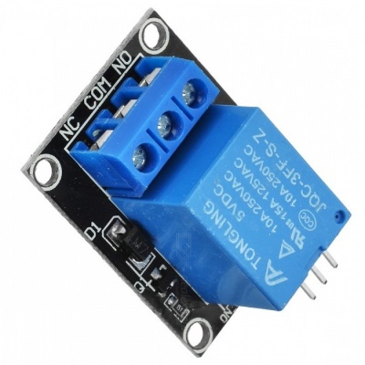
Introducing the Relay Module
A relay is an electrically operated switch. It means that it can be turned on or off, letting the current go through or not.
Controlling a relay with the Arduino is as simple as controlling an output such as an LED.
Notice the writing on the module terminals
COM: common pin
NO (Normally Open): there is no contact between the common pin and the normally open pin. So, when you trigger the relay, it connects to the COM pin, and supply is provided to a load
NC (Normally Closed): there is contact between the common pin and the normally closed pin. There is always a connection between the COM and NC pins, even when the relay is turned off. When you trigger the relay, the circuit is opened and there is no supply provided to a load.
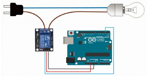
If you want to control a lamp, for example, it is better to use a normally open circuit, because we just want to light up the lamp occasionally.
Wiring
it is very straightforward as you can see. But always double-check the relay module connections before you plug things together.
GND: goes to ground
VCC: goes to 5V
IN1: controls the relay (it is connected to an Arduino digital pin)
OK, but maybe you want to control more than one thing??
then no porblem
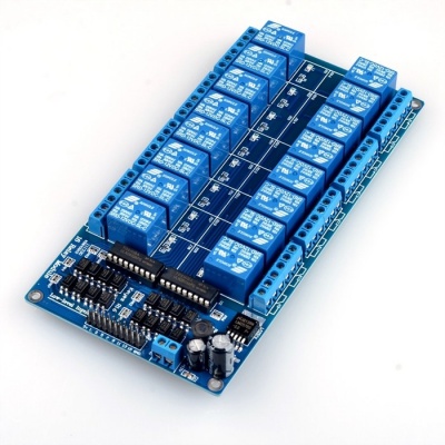
 here are 16 channels:)
The wiring is the same, you will just need 16 digital pins on the Arduino

