Difference between revisions of "Bleep Slider mini synth"
| (One intermediate revision by one other user not shown) | |||
| Line 196: | Line 196: | ||
=555 Timer / A classic= | =555 Timer / A classic= | ||
| + | The 555 timer IC is an integrated circuit (chip) used in a variety of timer, delay, pulse generation, and oscillator applications. | ||
| + | <br> | ||
| + | |||
| + | [[File:555timer.jpg | 500 px]] | ||
| + | <br> | ||
| + | |||
| + | We’ll be operating the 555 timer in astable mode. <br> | ||
| + | The astable 555 will emit pulses. The duration of that pulse, or rather the space between pulses, is typically determined by the values of a resistor between pins 7 & 8 that connects to VCC, and a capacitor between pin 6 and GND. While this is essentially true with this circuit (see schematic below), the value of that resistor (the photoresistor) will vary in relation to the amount of light being shined upon it. Thus when there is less light, there is more resistance, and the duration between the pulses increases, emitting a deeper pitch tone. When there is more light, there is less resistance, and the duration between pulses decreases, emitting a higher pitch tone. | ||
| + | <br> | ||
| + | <br> | ||
| + | <br> | ||
Make the little thing! | Make the little thing! | ||
=Clean up!= | =Clean up!= | ||
| + | |||
| + | [[Category:Electronics]] | ||
Latest revision as of 09:45, 21 November 2022
Learning goals: general station intro, practical electricity/electronics, components ( resistors, capacitors, IC, ldr, speaker), schematic, soldering
Intro, plus inspiration/context
Sculptural circuits
Peter Vogel and Alain le Boucher's sculptures
Peter Vogel's work is a result of his interests in dance and the body, composition, in psychology and neurobiology, physics and engineering, combined with a virtuosic craftsmanship in electronic circuit design.
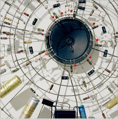
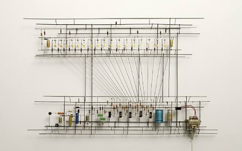
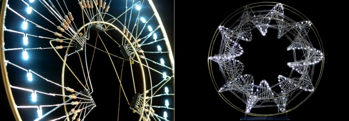
The light in Alain Le Boucher’s sculptures change depending on their programming, which he arranges like music. Through a transparent construction of fine metallic string, the movement and rhythm of light constantly transform the volume and give life to the sculpture.
Tatsuo Miyaijma
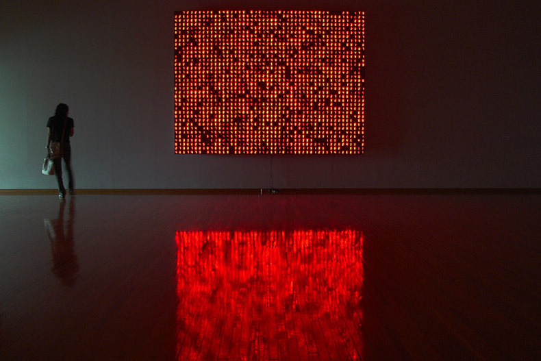
Time and our perception of time as expressed through an ongoing succession of numbers lie at the heart of Tatsuo Miyajima's practice.
His sculptural work consists of networks of colored digital LED devices and integrated circuits.
Humans since 1982
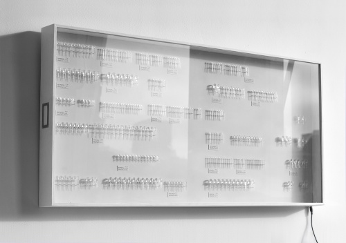
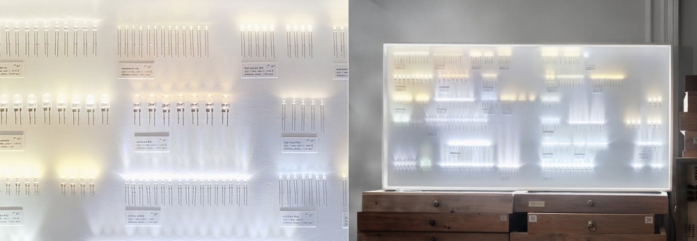
‘Collection of Light’ is simply a collection of LEDs which together constitute a lamp in itself.
The aim is to create an aura of a real collection (similar to a collection of insects) and expose each illuminant as a worthy industrial product.
The LEDs are all labeled (with name, size and colour temperature) and arranged in a specific order to accomplish harmonic light.
Crazy musical instruments
Ioana Vreme Moser
Ciat Lonbarde
crazy paper circuits paper circuit
Electronics stuff
Basic components
The BATTERY
is a source of electricity, that happens due to a chemical reaction.
There are many flavors of batteries. Different voltages, chemicals, sizes...
- There are also non-chemical batteries, for example solar batteries, they are an example of physical batteries
SWITCHES
Switches are electro-mechanical components that make or break one or more electrical contacts, thus allowing or preventing the flow of electrons ( the electric current), depending on the state of the switch. Above is its schematic symbol.
Drawn on the right, is a common switch, called a toggle switch. It connects the center terminal with the other outer terminals.
The center terminal is called the pole of the switch. Because you can flip, or throw, this switch to make two possible connections, it is called a double-throw switch. A single-pole, double-throw switch (like this one on the right) is abbreviated SPDT.
Some switches have two entirely separate poles, so you can make two separate connections simultaneously when you flip the switch. These are called double-pole switches.
here is another way to see the toggle switch above


And some examples of other types of switches
Single-pole Single-throw (makes only one connection with one pole. Its two states are simply open and closed)
and Double-pole Single-throw(makes two separate on/off connections)

There are switches that have three or four or more poles. But this is enough for a start:)
BUTTONS
Soo...... what about the buttons...they are also switches
like this one
They also come in many different flavors and colors, but they also interfere with the circuit, in most cases only while the button is pressed.
Like you computer keyboard buttons, when the key is pressed, something is happening, and when you let go, it stops.
A PUSHBUTTON is called a momentary switch, because it makes only a momentary contact. Any spring-loaded switch or button that wants to jump back to its original position is known as a momentary switch.
momentary switches can be NORMALLY OPEN (NO), meaning a that such a switch makes contact only when you push it, and flips back to make no contact when you let it go.
while a NORMALLY CLOSED (NC) button works the opposite way, it is normally ON, but when you push it, you break the connection. So, the OFF state is momentary.
that's how the symbols look like

RESISTORS
Resistors are the most beautiful components, small, delicate and colorful.
All they do is RESIST CURRENT!

The Resistance of a resistor is measured in Ohm (Ω), so guess.........you can use OHM'S LAW !
A * Ω = V or V / Ω = A
When 1mA flows through a 3.3kΩ resistor, there will be 3.3V across it. With 6V across a 120Ω resistor, a 50mA current will flow through it.
The resistance of the resistors ( or how many Ohms each resistor is) can be found by decoding the color stripes on it. And HAPPILY, there are a lot of online calculators that help you do this fast. [for example THIS one]
These resistors have a FIXED resistance,
but there are also VARIABLE RESISTORS a.k.a. POTENTIOMETERS
It is a resistor which resistance can be changed, by turning a knob. They can also look different, but commonly look like this
and the symbols for the resistors and pots

CAPACITORS
In ultra short - Capacitors are storage vessels for electric charge.
A capacitor stores energy - and then later releases it.
The Capacitance of a capacitor dictates how much energy can be stored, and is measured in Farad (F).
A steady current of 1mA will make the voltage across a 1μF capacitor rise with 1V per msec (= 1kV / sec).
Capacitors can be
CERAMIC - have no polarity (can be different colors and shapes)
ELECTROLYTIC - have a positive and negative leg ( the negative is marked by a stripe on the body of the capacitor) and its is important how you connect them, just like Leds.
there are also VARIABLE capacitors - but lets leave them for now
Reading a schematic
Soldering
555 Timer / A classic
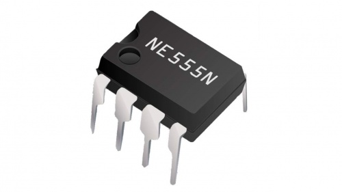
The 555 timer IC is an integrated circuit (chip) used in a variety of timer, delay, pulse generation, and oscillator applications.
We’ll be operating the 555 timer in astable mode.
The astable 555 will emit pulses. The duration of that pulse, or rather the space between pulses, is typically determined by the values of a resistor between pins 7 & 8 that connects to VCC, and a capacitor between pin 6 and GND. While this is essentially true with this circuit (see schematic below), the value of that resistor (the photoresistor) will vary in relation to the amount of light being shined upon it. Thus when there is less light, there is more resistance, and the duration between the pulses increases, emitting a deeper pitch tone. When there is more light, there is less resistance, and the duration between pulses decreases, emitting a higher pitch tone.
Make the little thing!
