Difference between revisions of "Design-batteryholder"
| (5 intermediate revisions by one other user not shown) | |||
| Line 1: | Line 1: | ||
Zooming in on the components of the first example http://interactionstation.wdka.hro.nl/wiki/Mona-lisa | Zooming in on the components of the first example http://interactionstation.wdka.hro.nl/wiki/Mona-lisa | ||
| − | '''The battery holder.''' | + | '''Boring stuff: The battery holder.''' |
First the boring part, how it works..... | First the boring part, how it works..... | ||
| Line 30: | Line 30: | ||
{| | {| | ||
| − | |[[file: bh1.png]] circuits form Tinkercad | + | |[[file: bh1.png|200px ]] circuits form Tinkercad |
| − | |[[file: bh2.png]]the circuit with the switch can be switched off and on | + | |[[file: bh2.png|200px]]the circuit with the switch can be switched off and on |
| − | |[[file: bh3.png]] Tinkercad tells you the LED gets too much current. | + | |[[file: bh3.png|200px]] Tinkercad tells you the LED gets too much current. |
|} | |} | ||
| Line 46: | Line 46: | ||
{| | {| | ||
| − | |[[file: bh4.png]] The LED's and the coin cell battery. | + | |[[file: bh4.png|200px]] The LED's and the coin cell battery. |
| − | |[[file: bh5.png]] The red one seems a bit "bright". | + | |[[file: bh5.png|200px]] The red one seems a bit "bright". |
| − | |[[file: bh6.png]] | + | |[[file: bh6.png|200px]] |
| − | |[[file: bh7.png]] The yellow one seems the right brightness | + | |[[file: bh7.png|200px]] The yellow one seems the right brightness |
|} | |} | ||
| Line 55: | Line 55: | ||
Now I choose a set up with a breadboard and some wires, then I can include the voltmeter inside the circuit. But this is working with "real" things, so it costs time.... | Now I choose a set up with a breadboard and some wires, then I can include the voltmeter inside the circuit. But this is working with "real" things, so it costs time.... | ||
| + | |||
| + | (I had to search the right boxes, for wires, for the breadboard, solder wires to a battery holder, get a male connector, search the alligator clips, realized my big multimeter is saving its small current fuse blown, had to search for the cheap multimeter.....) | ||
| + | |||
| + | {| | ||
| + | |[[file: bh21.png|200px]] | ||
| + | |[[file: bh22.png|200px]] | ||
| + | |[[file: bh23.png|200px]] | ||
| + | |[[file: bh24.png|200px]] | ||
| + | |- | ||
| + | |[[file: bh25.png|200px]] | ||
| + | |[[file: bh26.png|200px]] | ||
| + | |[[file: bh27.png|200px]] | ||
| + | |[[file: bh28.png|200px]] | ||
| + | |} | ||
| + | |||
| + | |||
| + | The experiments: | ||
| + | |||
| + | {| | ||
| + | |[[file: bh8.png|200px]] | ||
| + | |[[file: bh9.png|200px]] | ||
| + | |[[file: bh10.png|200px]] | ||
| + | |[[file: bh11.png|200px]] | ||
| + | |[[file: bh12.png|200px]] | ||
| + | |} | ||
| + | |||
| + | Now the values: | ||
| + | {| | ||
| + | |red led: 49 mA | ||
| + | | Tinkercad red: 61.9 mA | ||
| + | |- | ||
| + | |yellow led: 32 mA | ||
| + | | Tinkercad yellow: 61.9 mA | ||
| + | |- | ||
| + | |white led 1: 1.3 mA | ||
| + | | Tinkercad no white led | ||
| + | |- | ||
| + | |white led 2: 1.9 mA | ||
| + | | Tinkercad no white led | ||
| + | |- | ||
| + | |white led 3: 2.6 mA | ||
| + | | Tinkercad no white led | ||
| + | |} | ||
| + | |||
| + | Now the recommended value is according to Tinkercad 20 mA. | ||
| + | |||
| + | By measuring "in reality", we discovered that the white LED's, although bright, only have a tiny current! This might be important for other projects, where the current and energy is important, like energy harvesting circuits. The difference is really a factor 10! | ||
| + | |||
| + | ---- | ||
| + | |||
| + | '''Design Stuff''' | ||
| + | |||
| + | Now that we know that, what "design" can be make with this knowledge? | ||
| + | |||
| + | Well, this battery holder itself. It is only two pieces of conductive metal touching the plus and minus of the battery holder. We can not make a "better" battery holder, but we can certainly make "our own" battery holder. The materials will be more artistic, that is visually attractive, but also more "unreliable". | ||
| + | |||
| + | An example is a woven battery holder. | ||
| + | |||
| + | For this you need a baby loom. | ||
| + | |||
| + | You can build your own cardboard loom, for example: https://www.youtube.com/watch?v=A39PfntnTyo | ||
| + | |||
| + | I have my own a little bit more sophisticated baby loom: | ||
| + | |||
| + | [[file: bh31.png|200px]] | ||
| + | |||
| + | You can weave a small part, not on the whole width of the loom. | ||
| + | |||
| + | Then conductive thread can be inserted, in such a way that the woven piece folds just around the coin cell battery. | ||
| + | |||
| + | The other ends of the conductive thread are connected to the LED. | ||
| + | |||
| + | By opening and closing of the woven piece this woven battery holder is made into a battery holder with switch. | ||
| + | |||
| + | {| | ||
| + | |[[file: bh32.png|200px]] | ||
| + | |[[file: bh33.png|200px]] | ||
| + | |[[file: bh34.png|200px]] | ||
| + | |[[file: bh35.png|200px]] | ||
| + | |} | ||
| + | |||
| + | Weaving a piece, adding the conductive wires and the led costed me at least an hour, after having tried out how to do this. I am not at all satisfied with the "design" at the moment, the colors and materials used. This will be another afternoon or a day. | ||
| + | |||
| + | I already added even a programmed microcontroller with two LED's inside this woven piece, but that is for another post. | ||
| + | |||
| + | [[file: bh36.png|200px]] | ||
| + | |||
| + | More pictures of this "artistic" and messy battery holder can be found here: https://www.flickr.com/photos/contrechoc/albums/72157713148275338/with/49552903507/ | ||
..... | ..... | ||
| + | |||
| + | |||
| + | [[Category:Electronics]][[Category:Making]] | ||
Latest revision as of 10:16, 21 November 2022
Zooming in on the components of the first example http://interactionstation.wdka.hro.nl/wiki/Mona-lisa
Boring stuff: The battery holder.
First the boring part, how it works.....
The battery is for providing energy to your circuit.
Your circuit "works", so it consumes energy.
The battery....it seems so simple, you buy a battery. But there are so many batteries, which battery to buy?
let's keep this simpel: for a circuit with LED's , the most simple circuits you need a "coin-cell" battery of 3V.
The LED asks for a voltage that is near this value. There are different LED's, every color has it's own Voltage value.
Now you could and should ask: What is Voltage?
And this is a question which is not so easy to answer! Voltage is quite a complex notion and it takes time to explain, and even then......for instance:
https://www.youtube.com/watch?v=zYS9kdS56l8
https://www.youtube.com/watch?v=zqGvUbvVQXg
https://www.youtube.com/watch?v=F_vLWkkOETI
So let's do this in the practical way: we need a battery plus holder for a LED, we take the coin cell battery and holder and it "works" because it has nearly the right values.
We can "get" this battery holder in Tinkercad:
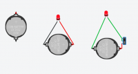 circuits form Tinkercad circuits form Tinkercad
|
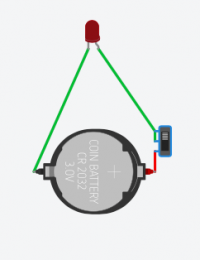 the circuit with the switch can be switched off and on the circuit with the switch can be switched off and on
|
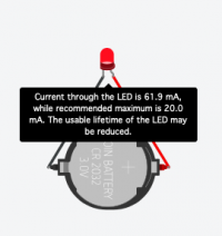 Tinkercad tells you the LED gets too much current. Tinkercad tells you the LED gets too much current.
|
If you start the simulation, it works! If you click on the LED in the second image, without the switch, you can get a comment, that there is something "wrong".
Now I would like to know if that is also true in "reality". So I have to make my circuit and measure. (wait a moment, because "reality" costs time!)
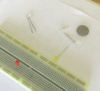
Time: I had to find the LED's in the boxes for LED's. I had to find a 3V battery Then I hade these, I wanted to take a picture, but my iPad was out of energy. I tried the USB microscope, but the image is blurry - too much distance. Then I discovered again how beautiful a LED is inside with this USB microscope (later page). My iPad got just enough charged, I could make these picture:
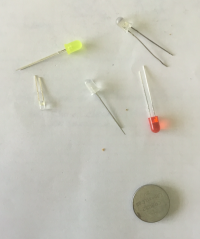 The LED's and the coin cell battery. The LED's and the coin cell battery.
|
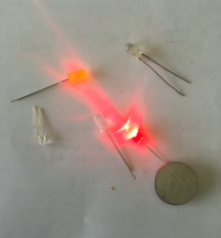 The red one seems a bit "bright". The red one seems a bit "bright".
|
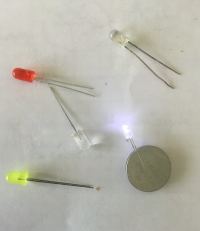
|
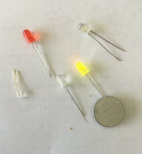 The yellow one seems the right brightness The yellow one seems the right brightness
|
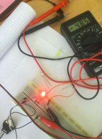
But how to measure the current? For this we need a volt meter - indeed it is called a multi meter, because we can measure, beside voltage also current, resistance and so on.
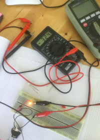
Now I choose a set up with a breadboard and some wires, then I can include the voltmeter inside the circuit. But this is working with "real" things, so it costs time....
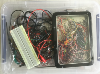
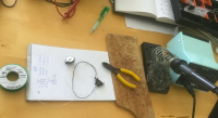
(I had to search the right boxes, for wires, for the breadboard, solder wires to a battery holder, get a male connector, search the alligator clips, realized my big multimeter is saving its small current fuse blown, had to search for the cheap multimeter.....)

|
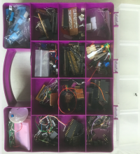
|
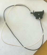
|
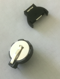
|
|
|

|
|
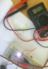
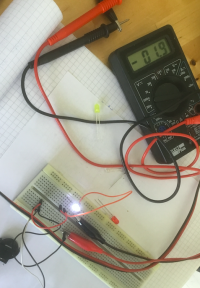
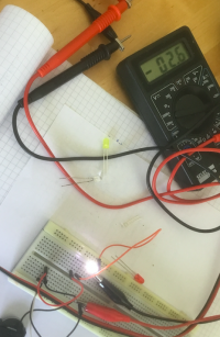
The experiments:
|
|
|
|
|
Now the values:
| red led: 49 mA | Tinkercad red: 61.9 mA |
| yellow led: 32 mA | Tinkercad yellow: 61.9 mA |
| white led 1: 1.3 mA | Tinkercad no white led |
| white led 2: 1.9 mA | Tinkercad no white led |
| white led 3: 2.6 mA | Tinkercad no white led |
Now the recommended value is according to Tinkercad 20 mA.
By measuring "in reality", we discovered that the white LED's, although bright, only have a tiny current! This might be important for other projects, where the current and energy is important, like energy harvesting circuits. The difference is really a factor 10!
Design Stuff
Now that we know that, what "design" can be make with this knowledge?
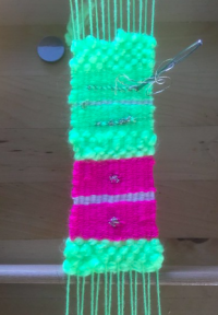
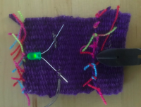
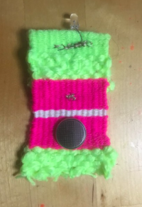
Well, this battery holder itself. It is only two pieces of conductive metal touching the plus and minus of the battery holder. We can not make a "better" battery holder, but we can certainly make "our own" battery holder. The materials will be more artistic, that is visually attractive, but also more "unreliable".
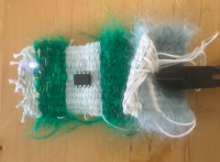
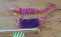
An example is a woven battery holder.
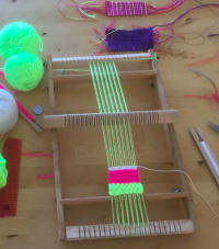
For this you need a baby loom.
You can build your own cardboard loom, for example: https://www.youtube.com/watch?v=A39PfntnTyo
I have my own a little bit more sophisticated baby loom:
You can weave a small part, not on the whole width of the loom.
Then conductive thread can be inserted, in such a way that the woven piece folds just around the coin cell battery.
The other ends of the conductive thread are connected to the LED.
By opening and closing of the woven piece this woven battery holder is made into a battery holder with switch.
|
|
|
|
Weaving a piece, adding the conductive wires and the led costed me at least an hour, after having tried out how to do this. I am not at all satisfied with the "design" at the moment, the colors and materials used. This will be another afternoon or a day.
I already added even a programmed microcontroller with two LED's inside this woven piece, but that is for another post.
More pictures of this "artistic" and messy battery holder can be found here: https://www.flickr.com/photos/contrechoc/albums/72157713148275338/with/49552903507/
.....
