Difference between revisions of "Late Night Soldering: Wind"
| (13 intermediate revisions by 3 users not shown) | |||
| Line 11: | Line 11: | ||
+some more great videos in case you can't get enough | +some more great videos in case you can't get enough | ||
<br> | <br> | ||
| − | [https://www.youtube.com/watch?v=akQao4VXYrA&list=PLWrcU8CrQu3twMmN7lD6PHQFRPxTZilXA&index=1 | + | [https://www.youtube.com/watch?v=jY1ZElnYIvk&list=PLWrcU8CrQu3twMmN7lD6PHQFRPxTZilXA&index=6 1] |
| − | [https://www.youtube.com/watch?v=yHFkaeDZJWs&list=PLWrcU8CrQu3twMmN7lD6PHQFRPxTZilXA&index=3 | + | [https://www.youtube.com/watch?v=akQao4VXYrA&list=PLWrcU8CrQu3twMmN7lD6PHQFRPxTZilXA&index=1 2] |
| + | [https://www.youtube.com/watch?v=yHFkaeDZJWs&list=PLWrcU8CrQu3twMmN7lD6PHQFRPxTZilXA&index=3 3] | ||
| + | |||
| Line 89: | Line 91: | ||
<br> | <br> | ||
<br> | <br> | ||
| + | |||
| + | So to understand better Ohm, we need a practical example....a simple circuit with a battery and a led. | ||
| + | |||
| + | |||
| + | So it is a good reason to get familiar with the breadboard. | ||
| + | |||
| + | ===Breadboarding=== | ||
| + | OK, first, what's with the name....bread board? Bread, like in food? | ||
| + | Well yes, kind of. | ||
| + | <br> | ||
| + | [[File:Breadboard.jpg ]] | ||
| + | |||
| + | This terminology goes way back in the days. | ||
| + | Generally, you would mount electronic components to a piece of wood (the actual "breadboard"), and do all the wiring with point-point wire and the components just hanging between the various devices. | ||
| + | <br><br> | ||
| + | [[File:Breadboardreal.jpg]] | ||
| + | <br><br> | ||
| + | The story goes that an engineer had an idea for a vacuum tube device late one night. Looking around the house, the only base for his prototype that he found was indeed his wife's breadboard, from the breadbox. | ||
| + | <br><br> | ||
| + | [http://www.youtube.com/watch?feature=player_embedded&v=HrG98HJ3Z6w A video by the Make magazine people ] | ||
| + | <br> | ||
| + | <br> | ||
| + | |||
| + | Ok, but why do we need to breadboard? | ||
| + | <br> | ||
| + | Well, they are useful for making temporary circuits and prototyping, and they require absolutely no soldering. | ||
| + | <br> | ||
| + | Prototyping is the process of testing out an idea by creating a preliminary model from which other forms are developed or copied, and it is one of the most common uses for breadboards. | ||
| + | <br> | ||
| + | The best way to explain how a breadboard works is to take it apart and see what’s inside. | ||
| + | [[File:Breadboard02.jpg]] | ||
| + | <br><br> | ||
| + | connections lines are connected like this | ||
| + | <br> | ||
| + | [[File:Breadboard03.jpg]] | ||
| + | |||
| + | <br> | ||
| + | === First circuit === | ||
| + | |||
| + | |||
| + | For an indicator LED that's often 20 mA. The LED will have a voltage across it, what's called the voltage drop. We also need that, it's also in the datasheet. The voltage drop mainly depends on the color, for a red LED 2 V is a typical value. | ||
| + | |||
| + | So with 2 V and 20 mA we can get to work. We're going to place a resistor in series with the LED to control the current. At 9 V battery voltage and a 2 V drop ( all electronic components exhibit - to a greater or lesser extent - what is know as 'dropout'. This has various abbreviations depending on the type of component to which it refers, but they generally mean the same thing. It's actually the amount of voltage which is used up by the component in order to function. ) across the LED we'll have 7 V remaining for the resistor. Then according to Ohm's Law Voltage = Current x Resistance, we can calculate the resistor value as | ||
| + | <br> | ||
| + | '''R=VxI=7Vx20mA=350Ω''' | ||
| + | <br> | ||
| + | [[File:Ledresitor.png]] | ||
| + | <br> | ||
| + | |||
==Electromagnetism== | ==Electromagnetism== | ||
| Line 186: | Line 237: | ||
===Solenoids=== | ===Solenoids=== | ||
| − | Solenoids work like a motor that | + | Solenoids work like a motor that moves in or out instead of spinning. A solenoid consists of a housing, a plunger, and usually a spring that returns the plunger to a resting state once the power is off. There’s a coil of wire around the plunger, and when electricity flows through that coil, it either attracts or repels the plunger to give you a short, linear stroke—good for pushing buttons and making robotic instruments. |
An old doorbell, it most likely has a solenoid in it. When you press the button, it closes a circuit that makes a solenoid turn on, which moves the plunger and hits a chime. | An old doorbell, it most likely has a solenoid in it. When you press the button, it closes a circuit that makes a solenoid turn on, which moves the plunger and hits a chime. | ||
<br> | <br> | ||
| Line 222: | Line 273: | ||
<br> | <br> | ||
| − | *Add a '''Gear System''' | + | [[File:Joulethief.jpg]] |
| + | <br> | ||
| + | and that's basically how it looks like, only in this case it's used to amplify the very little energy left in this battery, to power up a led. \ | ||
| + | <br> | ||
| + | [[File:Joulethief01.jpg | 500 px]] | ||
| + | <br> | ||
| + | |||
| + | |||
| + | *Add a '''Gear System''' to MULTIPLY SPEED (can be used with steppers too:) | ||
| + | |||
| + | A gear combination can also be used to magnify force or magnify speed. | ||
| + | |||
| + | Just like the bike gears, that allow the rider to trade extra force for increased speed, or sit back and pedal easily, at the expense of going slower. | ||
| + | |||
| + | |||
| + | An '''input gear''' is the one that the force is applied to. (in our particular case, is what the wind turns) and an '''output gear''' is the one that is being driven ( in our case the motor shaft). | ||
| + | |||
| + | To use a gear train to '''magnify speed''', the big gear is the input gear and the small one is the output. The disadvantage is that we need to apply more power to the input but the speed of the output is magnified. | ||
| + | <br> | ||
| + | <br> | ||
| + | When the gear train is being used to '''magnify force''', the input gear will always be smaller than the output gear. This setup is great when you have a motor and need to multiply the work it can do by itself, or when you need to slow the motor’s output to a speed that fits your application. | ||
| + | <br> | ||
| + | [[File:Gearratio.gif]] | ||
| + | <br> | ||
| + | <br> | ||
| + | '''Make your OWN GEARS with INKSCAPE''' ( an open source vector software, similar to illustrator, but free) | ||
| + | [[File:Inkscape logo.jpg | 200 px]] | ||
| + | [http://inkscapetutorials.org/2008/05/01/drawing-gears-in-inkscape-a-howto-by-nicu/ HERE IS A TUTORIAL LINK] | ||
| + | |||
| + | ===Stepper motors strategies=== | ||
| + | |||
| + | As we know stepper generators are alternators, meaning they bring us AC. In order to make use of AC in DC applications, we need to build a rectifier. | ||
| + | A rectifier is an electrical device that converts alternating current (AC), which periodically reverses direction, to direct current (DC), which flows in only one direction. The process is called rectification. | ||
| + | |||
| + | This can be a deep topic, so we keep it simple. | ||
| + | |||
| + | <br> | ||
| + | |||
| + | We will build a '''DIODE BRIDGE RECTIFIER''' | ||
| + | |||
| + | The simplest (full wave) bridge rectifier is made up of just four diodes (components which allow electricity to flow in just one direction). | ||
| + | Below you can see how the four diodes are wired together and also shows how electricity flows through it as the current alternates. | ||
| + | |||
| + | [[File:Bridgerectifier.gif ]] | ||
==Wind Turbines== | ==Wind Turbines== | ||
| Line 266: | Line 360: | ||
| − | + | ||
| − | [[Category: | + | |
| + | [[Category:Electronics]] | ||
[[Category:Motors]] | [[Category:Motors]] | ||
Latest revision as of 12:10, 21 November 2022
Intro
poetry and electricity
Before we go any further, I think it’s worth it to spend a bit of time watching a video . Since we use electricity as means to make work, its nice to have some understanding it. There are thousands of videos online, but this one is a pearl from 1945...........really different from any tutorial on youtube, see for yourself
WATCH ME
+some more great videos in case you can't get enough
1
2
3
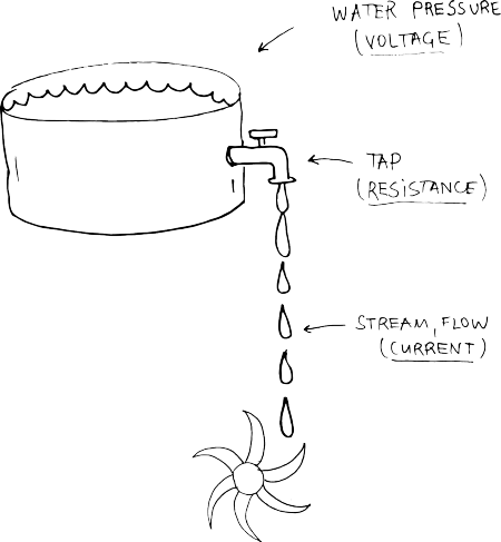
Electricity seems to be both familiar and yet abstract. Its quite hard to imagine. In order imagine electricity, an analogy with water is often used.
Electricity is an essential ingredient of matter. Now ain't that poetic? So to picture it, lets zoom deep in and look at the smallest component of every element - 
Atoms are made of even smaller particles called protons, neutrons, and electrons. The protons and neutrons are packed tightly together in the middle of the atom, and we call them the nucleus of the atom. The electrons orbit around the nucleus. Protons and electrons have electrical charges. Protons have a positive charge, and electrons have a negative charge (neutrons don't have any charge). Normally an atom has equal numbers of protons and electrons, so they cancel each other and the atom has no electrical charge.
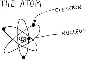
Sometimes an electron escapes from its atom and runs off to join another atom.
Atoms with escaped electrons is positively charged and respectively, if electrons jump into atoms and become more, then the atom is negatively charged.
Free atoms can move freely (almost with the speed of light) trough metals, gases and vacuum. Or they can rest.
The surface that electrons are resting is said to have negative static electrical charge. If atoms are missing some electrons then it is said to be positive static electrical charge.
Current, Voltage, Power, Resistance
So anytime electrons move, we have current! Electrons can travel trough some materials but not trough others. The ones that allow electrons to flow are called Conductors (silver, gold, iron, copper..etc.) and the ones that do not really allow the free flow of electrons are called Insulators ( wood, plastic, rubber..etc.)
Electrical current can flow in either of two directions in a conductor. If it flows only in one direction, then it is called DC ( Directional Current). We will work with it and so the following information concerns DC.
CURRENT (I) - is the quantity of electrons passing at a given point. The unit is the AMPERE, shortly called AMP. If we compare it with water, think of it as the flow of water, the stream coming from the tap.
VOLTAGE (V or E) - is electrical pressure or force. If we now compare it with water, then Voltage is the water pressure.
The higher the pressure, the higher the flow and vice versa.
POWER (P) - is the work performed by an electrical current. It is measured in WATT. The power of a DC current is its voltage(V), times its current(I).
RESISTANCE (R) - is the conductor's (material’s) tendency to resist the current. Some materials allow more current to flow and others not. Going back to water, resistance is how much the tap is open. It is measured in OHMS (Ω).
OHM's LAW
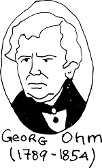
Mr. Georg Simon Ohm, a German physicist and mathematician, discovered, that there is an interrelation between Voltage, Current and Resistance.
Thus given any two of them, one can find the third one.
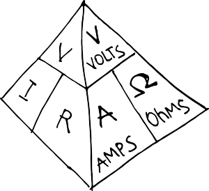
V = IxR
I = V/R
R= V/I
Here is a pyramid that shows it visually.
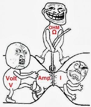
And shows also the actuial relationship between volts, amps and ohms, which you will see way more often than V, I and R
And here another way we can see it:)
So to understand better Ohm, we need a practical example....a simple circuit with a battery and a led.
So it is a good reason to get familiar with the breadboard.
Breadboarding
OK, first, what's with the name....bread board? Bread, like in food?
Well yes, kind of.
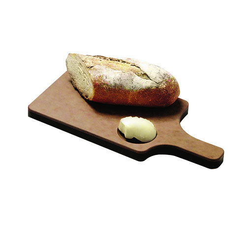
This terminology goes way back in the days.
Generally, you would mount electronic components to a piece of wood (the actual "breadboard"), and do all the wiring with point-point wire and the components just hanging between the various devices.
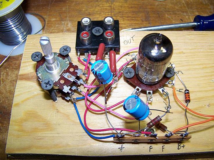
The story goes that an engineer had an idea for a vacuum tube device late one night. Looking around the house, the only base for his prototype that he found was indeed his wife's breadboard, from the breadbox.
A video by the Make magazine people
Ok, but why do we need to breadboard?
Well, they are useful for making temporary circuits and prototyping, and they require absolutely no soldering.
Prototyping is the process of testing out an idea by creating a preliminary model from which other forms are developed or copied, and it is one of the most common uses for breadboards.
The best way to explain how a breadboard works is to take it apart and see what’s inside.
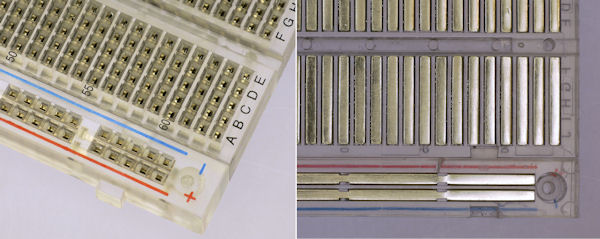
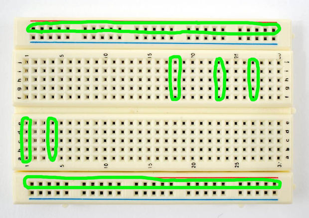
connections lines are connected like this
First circuit
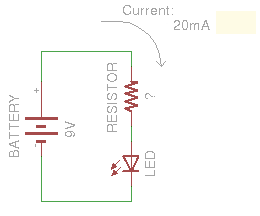
For an indicator LED that's often 20 mA. The LED will have a voltage across it, what's called the voltage drop. We also need that, it's also in the datasheet. The voltage drop mainly depends on the color, for a red LED 2 V is a typical value.
So with 2 V and 20 mA we can get to work. We're going to place a resistor in series with the LED to control the current. At 9 V battery voltage and a 2 V drop ( all electronic components exhibit - to a greater or lesser extent - what is know as 'dropout'. This has various abbreviations depending on the type of component to which it refers, but they generally mean the same thing. It's actually the amount of voltage which is used up by the component in order to function. ) across the LED we'll have 7 V remaining for the resistor. Then according to Ohm's Law Voltage = Current x Resistance, we can calculate the resistor value as
R=VxI=7Vx20mA=350Ω
Electromagnetism
The word "electromagnetism" in physics is used to describe one of the fundamental forces of nature. This force is between subatomic particles such as protons and electrons. It helps to hold matter together.
Electromagnetism is also used to describe how a magnetic field is created by the flowing of electric current.
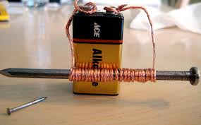
Electromagnet
When an electronic current flows through a wire, it generates a magnetic field. This is an important concept in electricity. The magnetic field can be increased by coiling the wire. This allows more current to flow through a smaller distance and increases the magnetic field.
Motors
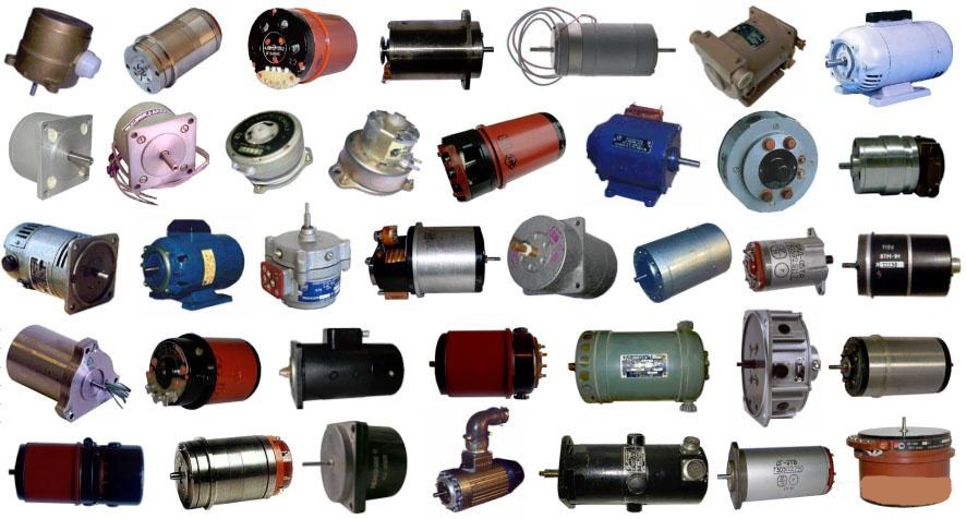
One of the important applications of electromagnetism is the electric motor. An electric motor converts electrical energy into physical movement. Electric motors generate magnetic fields with electric current through a coil. The magnetic field then causes a force with a magnet that causes movement or spinning that runs the motor.
Induction
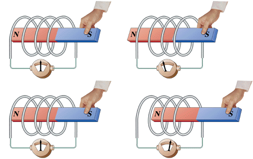
Another important application of electromagnetism is induction. Induction is when movement is used to create electricity (the opposite of using electricity to create movement). As a wire is moved through a magnetic field, current will begin to flow through it.
OK, again, If the strength of a magnetic field changes, it can induce a flow of current through a conductor. This is basically how most electrical power is generated. Huge magnets move around inside massive coils of wire.
Motors
Motors turn electrical energy into mechanical energy using coiled-up wires and magnets. When electricity flows through a wire, it creates a magnetic field around it. When you bring a permanent magnet close to that magnetic field, it will be repelled or attracted. Motors take advantage of this magnetic field by mounting coils of wire on a shaft, so when the magnet repels the coils, the shaft begins to spin. In order to keep the shaft spinning, you need to keep flipping the magnetic field so the series of repel, attract, repel, and so on continues and the shaft keeps spinning. Different motors do this in different ways.
dc
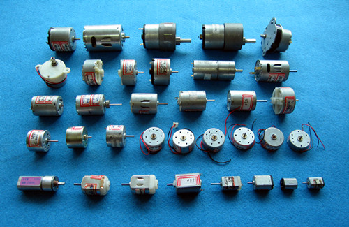
The most basic motor you’ll use is the standard DC motor. You can find them in everything from rc cars to electric toothbrushes. Motors consist basically of wire windings and permanent magnets.
When the motor windings become energized, a temporary magnetic field is created that repels(and/or attracts) against permanent magnets. This force is converted into shaft rotation, which allows the motor to do work. As the shaft rotates, electric current is routed to different sets of windings, maintaining electromotive repulsion/attraction, forcing the rotor to continually turn.
[dc motors]
in construction dc motors can be:
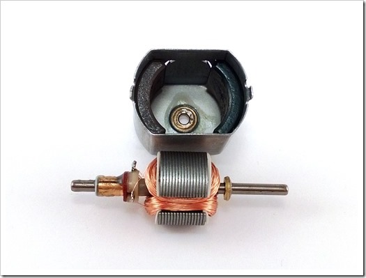
brushed
the coils are the rotating part with the shaft secured to them. Thus there is a need of brushes in order to make contact with the coils.
the permanent magnets are the static part of the motor.
brushless
is a slightly more complicated construction. the windings are stationary. we won't go into much details now.
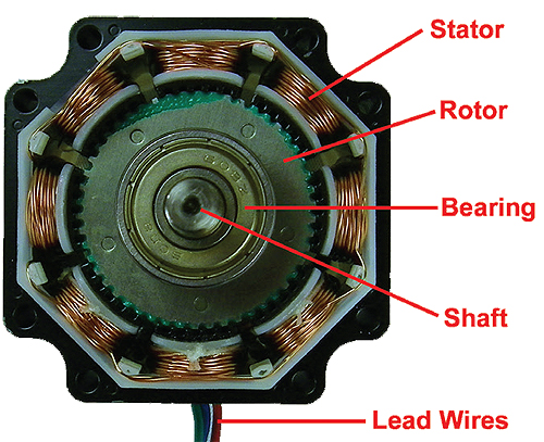
Windings are on the rotor (Rotating part of motor) for brush motors and on the stator (stationary part of motor) for brushless motors.
DC motors usually need between 1.5V and 12V. They spin at speeds anywhere from 1,000 to 20,000 rpm or more.
DC gearhead motor
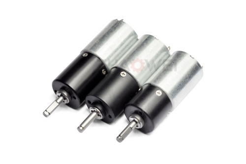
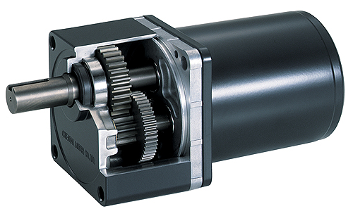
There are also DC gearhead motor. This is just a standard DC motor with a gearhead on it. A gearhead is just a box of gears that takes the output shaft of the standard DC motor and “gears it up” to a second output shaft
that has higher torque, but turns slower. How much slower depends on the gear ratio. Here, we’re trading speed for torque.
servo
There are two types of servo motors: standard and continuous rotation. Servo refers to any motor with built-in feedback of some sort. Feedback just means there is some way to know where the output shaft is.
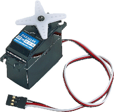
Standard hobby servo motors are just little DC gearhead motors with some additives
in them (circuitry). When you give the electronics a certain kind of pulse— basically just turning the power on and off in a specific pattern—you’re actually telling the servo motor where to point the shaft.
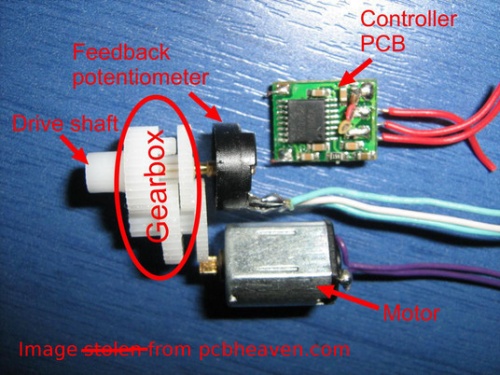
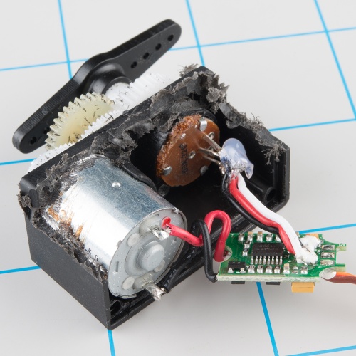
Instead of having just two wires you attach to a power source like the DC motors described earlier, these motors have three wires and are controlled by pulses. Standard servos have ranges between 60° and 270° (typically 180°), so they are most useful for pointing and positioning tasks.
Continuous Rotation Hobby Servos
A continuous rotation servo is a modification of the standard servo motor. Instead of determining position, the pulses tell the motor how fast to go. You give up knowing the position of the servo arm here, but you gain speed control and 360° movement.
stepper
The stepper motor combines the precise positioning of standard servos and the continuous rotation of DC motors. The central shaft of a stepper has a series of magnets on it , and there are several wire coils surrounding this gear magnet on the inside of the motor housing.
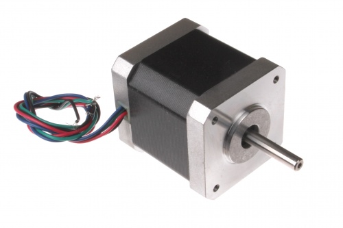
Steppers work by moving in a bunch of little increments, or steps. If you step them fast enough, it looks like continuous motion. Each time one of the coils is energized, it pulls one of the teeth on the shaft toward it to complete one step. For example, a 200-step motor moves in a full 360° circle at 1.8° per step.
These motors have four to eight wires you need to use to control the pulses to make the shaft step continuously, so they’re more complicated to control than the previously described motors. They are squatter looking than the rest of the DC motor family, and have less torque than you might expect for their size and weight. However, they’re also the fastest way to integrate both speed and position control into a project.
Solenoids
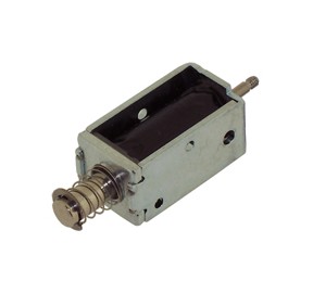
Solenoids work like a motor that moves in or out instead of spinning. A solenoid consists of a housing, a plunger, and usually a spring that returns the plunger to a resting state once the power is off. There’s a coil of wire around the plunger, and when electricity flows through that coil, it either attracts or repels the plunger to give you a short, linear stroke—good for pushing buttons and making robotic instruments.
An old doorbell, it most likely has a solenoid in it. When you press the button, it closes a circuit that makes a solenoid turn on, which moves the plunger and hits a chime.
Generators /dynamos, alternators/
a generator is a device that converts mechanical energy to electrical energy
Electric generators convert mechanical energy into electrical energy using induction. As a coil of wire is spun between two opposite magnets, an electric current is generated.
Electromagnetic generators fall into one of two broad categories, dynamos and alternators.
- Dynamos generate direct current, usually with voltage or current fluctuations, usually through the use of a commutator (look at the video for DC motors)
- Alternators generate alternating current, which may be rectified by another (external or directly incorporated) system.
Caching the wind
Normally, when you give electricity to a motor, it spins. Like we saw and discussed.
The same is true in reverse: If you give a motor a spin, it acts as a generator and creates electricity.
DC motors will create direct current in one or the other direction depending on the direction the shaft is spinning ( they are dynamos)
Servo motors will give us alternating current ( they are alternators). Thus is order to use it for dc applications, we have to make a circuit that rectifies the electricity and therefore transforms it into DC.
So using this simple concept we will try to harvest the wind.
DC motors strategies
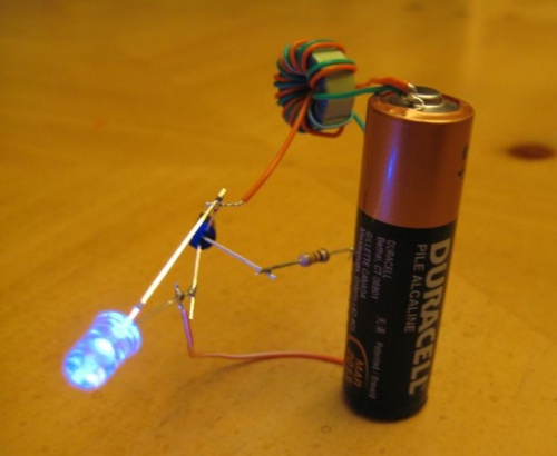
- Add a Joule Thief Circuit / a lightweight voltage booster /
A “Joule Thief” is a simple voltage booster circuit. It can increase the voltage of a power source by changing the constant low voltage signal into a series of rapid pulses at a higher voltage. You most commonly see this kind of circuit used to power LEDs with a “dead” battery, but there are many more applications for a circuit like this. Like boosting the voltage we get from the DC motor generator.
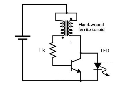
and that's basically how it looks like, only in this case it's used to amplify the very little energy left in this battery, to power up a led. \
- Add a Gear System to MULTIPLY SPEED (can be used with steppers too:)
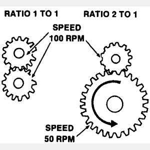
A gear combination can also be used to magnify force or magnify speed.
Just like the bike gears, that allow the rider to trade extra force for increased speed, or sit back and pedal easily, at the expense of going slower.
An input gear is the one that the force is applied to. (in our particular case, is what the wind turns) and an output gear is the one that is being driven ( in our case the motor shaft).
To use a gear train to magnify speed, the big gear is the input gear and the small one is the output. The disadvantage is that we need to apply more power to the input but the speed of the output is magnified.
When the gear train is being used to magnify force, the input gear will always be smaller than the output gear. This setup is great when you have a motor and need to multiply the work it can do by itself, or when you need to slow the motor’s output to a speed that fits your application.
Make your OWN GEARS with INKSCAPE ( an open source vector software, similar to illustrator, but free)
 HERE IS A TUTORIAL LINK
Stepper motors strategies
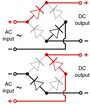
As we know stepper generators are alternators, meaning they bring us AC. In order to make use of AC in DC applications, we need to build a rectifier. A rectifier is an electrical device that converts alternating current (AC), which periodically reverses direction, to direct current (DC), which flows in only one direction. The process is called rectification.
This can be a deep topic, so we keep it simple.
We will build a DIODE BRIDGE RECTIFIER
The simplest (full wave) bridge rectifier is made up of just four diodes (components which allow electricity to flow in just one direction). Below you can see how the four diodes are wired together and also shows how electricity flows through it as the current alternates.
Wind Turbines
Horizontal axis
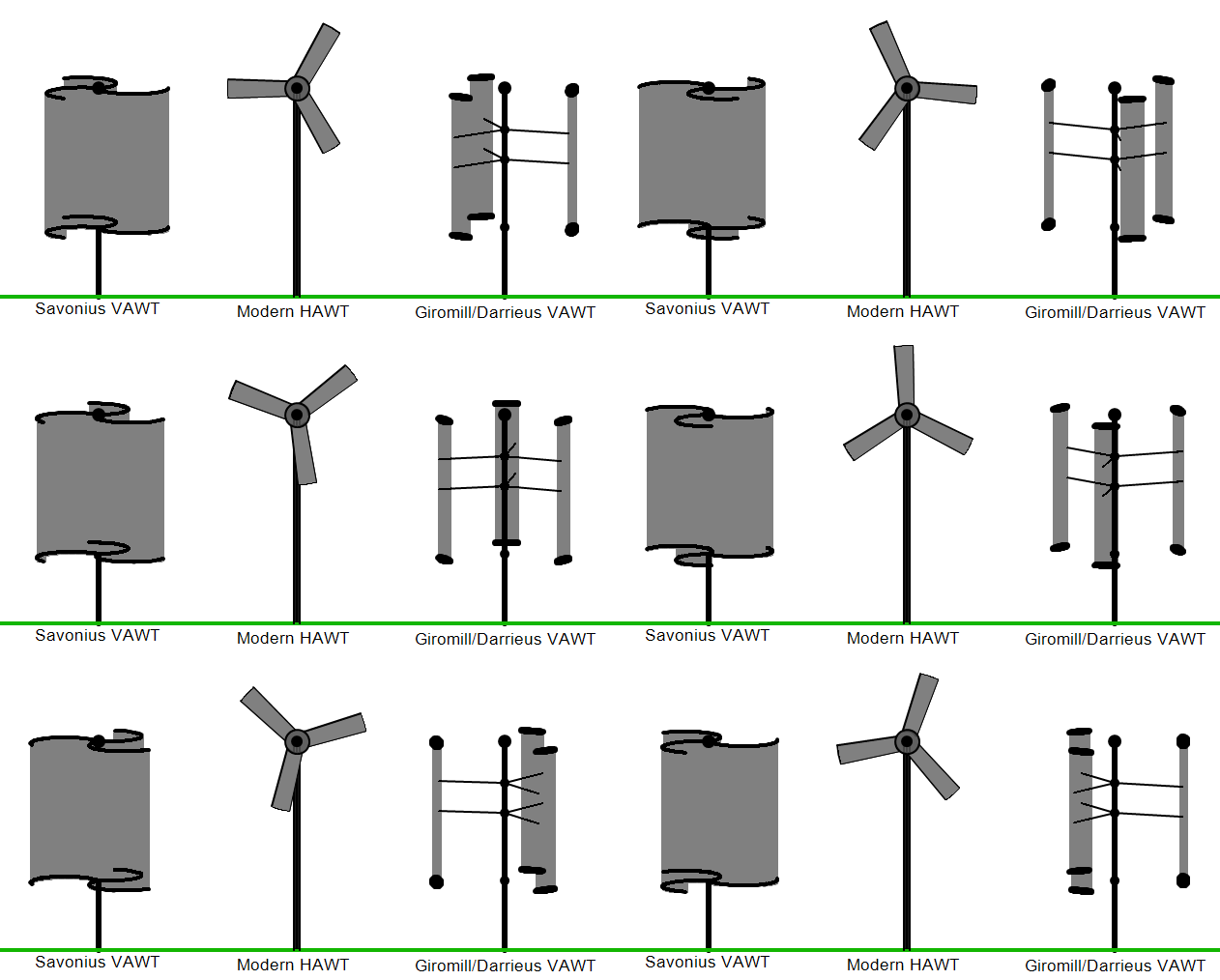
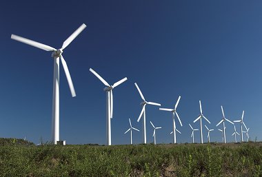
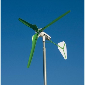
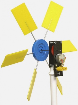
Horizontal-axis wind turbines (HAWT) have the main rotor shaft and electrical generator at the top of a tower, and must be pointed into the wind. Most have a gearbox, which turns the slow rotation of the blades into a quicker rotation that is more suitable to drive an electrical generator
Vertical Axis
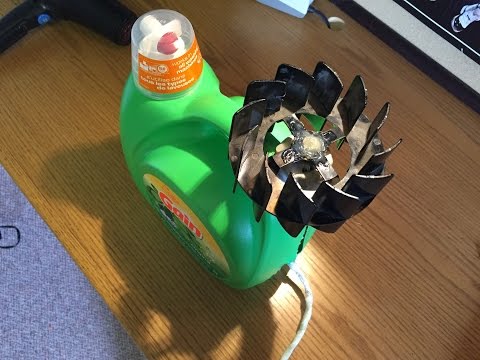
Vertical-axis wind turbines (or VAWT) have the main rotor shaft arranged vertically. One advantage of this arrangement is that the turbine does not need to be pointed into the wind to be effective, which is an advantage on a site where the wind direction is highly variable. It is also an advantage when the turbine is integrated into a building because it is inherently less steerable. Also, the generator and gearbox can be placed near the ground, using a direct drive from the rotor assembly to the ground-based gearbox, improving accessibility for maintenance. The key disadvantages include the relatively low rotational speed with the consequential higher torque and hence higher cost of the drive train, the inherently lower power coefficient
types of VAWT
Darrieus wind turbine
Darrieus wind turbines are commonly called "Eggbeater" turbines, because they look like a giant eggbeater.
Savonius wind turbine
A Savonius is a drag type turbine, they are commonly used in cases of high reliability in many things such as ventilation and anemometers. Because they are a drag type turbine they are less efficient than the common HAWT. Savonius are excellent in areas of turbulent wind.
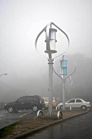 combination of Darrieus and Savonius
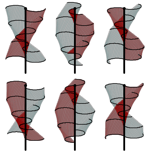
Twisted Savonius
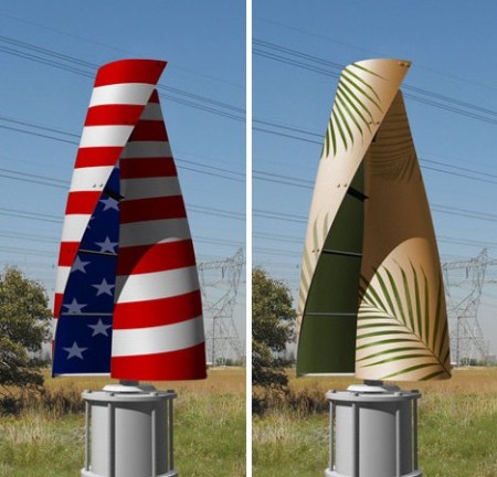
Twisted Savonius is a modified savonius, with long helical scoops to provide smooth torque.

