Difference between revisions of "Thermistor"
| (12 intermediate revisions by one other user not shown) | |||
| Line 37: | Line 37: | ||
Serial.print(Tc); | Serial.print(Tc); | ||
Serial.println(" C"); | Serial.println(" C"); | ||
| + | |||
| + | if ( Tc < 10 ) | ||
| + | { | ||
| + | Serial.print("Temperature below 10 "); | ||
| + | } | ||
delay(500); | delay(500); | ||
| Line 51: | Line 56: | ||
Yes if you have the right thermistor, you can copy the script and it works (sort of, see later...). | Yes if you have the right thermistor, you can copy the script and it works (sort of, see later...). | ||
| − | + | But then I bought another NTC sensor, connected it and it gave a wrong reading. | |
| − | But then I bought another NTC sensor, connected it and it | ||
{| class="wikitable" style="border-style: solid; border-width: 20px" | {| class="wikitable" style="border-style: solid; border-width: 20px" | ||
|+ | |+ | ||
| − | [[File:ntc10.png]] | + | | [[File:ntc10.png]] |
|} | |} | ||
| Line 66: | Line 70: | ||
http://www.produktinfo.conrad.com/datenblaetter/550000-574999/557281-da-01-en-NTC_THERMISTOR_TTS1A104F4363RY.pdf | http://www.produktinfo.conrad.com/datenblaetter/550000-574999/557281-da-01-en-NTC_THERMISTOR_TTS1A104F4363RY.pdf | ||
| − | |||
| − | |||
But this datasheet didn't explain anything. So I had to understand something more, which is difficult if you only want to copy paste a script and preferably don't think too much. | But this datasheet didn't explain anything. So I had to understand something more, which is difficult if you only want to copy paste a script and preferably don't think too much. | ||
| − | |||
| − | |||
So I found this site explaining: | So I found this site explaining: | ||
| Line 77: | Line 77: | ||
https://components101.com/ntc-thermistor-10k | https://components101.com/ntc-thermistor-10k | ||
| − | + | {| class="wikitable" style="border-style: solid; border-width: 20px" | |
| + | |+ | ||
| + | | [[File:ntc11.png]] | ||
| + | |} | ||
| − | [[File: | + | |
| + | Going back to the datasheet I found this B value they are talking about in this link: for this NTC the B = 3935 - from this big table: (find the B502 line) | ||
| + | |||
| + | {| class="wikitable" style="border-style: solid; border-width: 20px" | ||
| + | |+ | ||
| + | | [[File:ntc12.png]] | ||
| + | |} | ||
Looking at the graphic: | Looking at the graphic: | ||
| − | I somehow understood this T0, room temperature, 25 degrees constant of 5K Ohm. I measured the resistance to be around 7K for 16 degrees, so this fitted. | + | {| class="wikitable" style="border-style: solid; border-width: 20px" |
| + | |+ | ||
| + | | [[File:ntc13.png]] | ||
| + | |} | ||
| + | |||
| + | I somehow understood this T0, room temperature, 25 degrees constant of 5K Ohm. I measured the resistance to be around 7K for 16 degrees, so this fitted. Be careful, because the temperature scale is "lineair" and the Resistance is "log" scale, so you cannot fit the behavior of the thermistor linearly, by measuring 0 degrees and 100 degrees and interpolate using a simple formula. (I did this a few years ago....wrong!!!) | ||
But then I have some constants, how to arrive at the c1, c2, c3? | But then I have some constants, how to arrive at the c1, c2, c3? | ||
| Line 89: | Line 103: | ||
Above is mentioned the Steinhart formula...indeed, but then not yet the script version.... | Above is mentioned the Steinhart formula...indeed, but then not yet the script version.... | ||
| − | R=R0 expB (1/T-1/T0) | + | R=R0 expB (1/T-1/T0) -- this is a real formula! Not a coded line, relating the Resistance R to the temperature T, involving 1/T and exponentials (log). |
You have to work this around, getting the T from the measured resistance, and the resistance from the voltage divider (hardware, connected to the microcontroller). | You have to work this around, getting the T from the measured resistance, and the resistance from the voltage divider (hardware, connected to the microcontroller). | ||
| Line 95: | Line 109: | ||
So....we have to do some equation acrobatics | So....we have to do some equation acrobatics | ||
| − | log(R/R0) = B (1/T - 1/T0) | + | log(R/R0) = B*(1/T - 1/T0) |
| − | |||
log(R/R0)/B = 1/T - 1/T0 | log(R/R0)/B = 1/T - 1/T0 | ||
| − | |||
1/T = log(R/R0)/B - 1/T0 | 1/T = log(R/R0)/B - 1/T0 | ||
| − | |||
T = 1 / ( log(R/R0)/B - 1/T0 ) | T = 1 / ( log(R/R0)/B - 1/T0 ) | ||
| − | For the script then, we need | + | For the script then, we need coding this last line - calculating the last T = ... formula, the following script calculates first the constants, Kelvin to Celsius etcetera, then the final verdict: |
| + | <syntaxhighlight lang=c style="border:3px dashed pink"> | ||
float steinhart; | float steinhart; | ||
steinhart = average / THERMISTORNOMINAL; // (R/Ro) | steinhart = average / THERMISTORNOMINAL; // (R/Ro) | ||
| Line 112: | Line 124: | ||
steinhart = 1.0 / steinhart; // Invert | steinhart = 1.0 / steinhart; // Invert | ||
steinhart -= 273.15; // convert to C | steinhart -= 273.15; // convert to C | ||
| + | </syntaxhighlight> | ||
found at adafruit: | found at adafruit: | ||
| Line 153: | Line 166: | ||
This hurts, it is called learning...terrible..... | This hurts, it is called learning...terrible..... | ||
| + | |||
| + | [[Category:Electronics]][[Category:Sensors]] | ||
Latest revision as of 09:09, 22 November 2022
Using a Thermistor (temperature sensor)
In short: Thermistors change resistance with a change in temperature.
They are classified by the way their resistance responds to temperature changes. In Negative Temperature Coefficient (NTC) thermistors, resistance decreases with an increase in temperature. In Positive Temperature Coefficient (PTC) thermistors, resistance increases with an increase in temperature. In this example we are using an NTC thermistor.
Since the thermistor is a variable resistor, we’ll need to measure the resistance before we can calculate the temperature. However, the Arduino can’t measure resistance directly, it can only measure voltage.
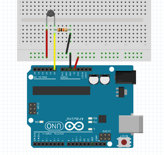
The Arduino will measure the voltage at a point between the thermistor and a known resistor. This is known as a voltage divider.
Then, the Steinhart-Hart equation is used to convert the resistance of the thermistor to a temperature reading.
int ThermistorPin = 0;  //// which analog pin to connect
int Vo;
float R1 = 10000;
float logR2, R2, T, Tc;
float c1 = 1.009249522e-03, c2 = 2.378405444e-04, c3 = 2.019202697e-07;

void setup() {
Serial.begin(9600);
}

void loop() {

  Vo = analogRead(ThermistorPin);
  R2 = R1 * (1023.0 / (float)Vo - 1.0);
  logR2 = log(R2);
  T = (1.0 / (c1 + c2*logR2 + c3*logR2*logR2*logR2));
  Tc = T - 273.15;

  Serial.print("Temperature: ");

  Serial.print(Tc);
  Serial.println(" C");

 if ( Tc < 10 )
 {
 Serial.print("Temperature below 10 ");
 }

  delay(500);
}
And then Beam said:
Yes if you have the right thermistor, you can copy the script and it works (sort of, see later...). But then I bought another NTC sensor, connected it and it gave a wrong reading.

|
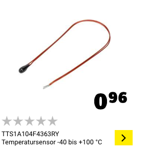
It was a real NTC thermistor, bought at Conrad a long time ago, but Conrad didn't sell it anymore: TTS2B502F39D3RY.
What to do? These numbers c1, c2, c3 are not something you can fiddle with just like that...
On another site of Conrad the datasheet was still to be downloaded, although the part was not available anymore.
But this datasheet didn't explain anything. So I had to understand something more, which is difficult if you only want to copy paste a script and preferably don't think too much.
So I found this site explaining:
https://components101.com/ntc-thermistor-10k

|
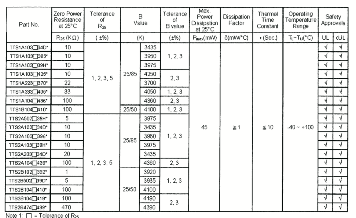
Going back to the datasheet I found this B value they are talking about in this link: for this NTC the B = 3935 - from this big table: (find the B502 line)

|
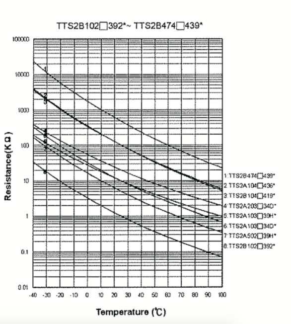
Looking at the graphic:

|
I somehow understood this T0, room temperature, 25 degrees constant of 5K Ohm. I measured the resistance to be around 7K for 16 degrees, so this fitted. Be careful, because the temperature scale is "lineair" and the Resistance is "log" scale, so you cannot fit the behavior of the thermistor linearly, by measuring 0 degrees and 100 degrees and interpolate using a simple formula. (I did this a few years ago....wrong!!!)
But then I have some constants, how to arrive at the c1, c2, c3?
Above is mentioned the Steinhart formula...indeed, but then not yet the script version....
R=R0 expB (1/T-1/T0) -- this is a real formula! Not a coded line, relating the Resistance R to the temperature T, involving 1/T and exponentials (log).
You have to work this around, getting the T from the measured resistance, and the resistance from the voltage divider (hardware, connected to the microcontroller).
So....we have to do some equation acrobatics
log(R/R0) = B*(1/T - 1/T0)
log(R/R0)/B = 1/T - 1/T0
1/T = log(R/R0)/B - 1/T0
T = 1 / ( log(R/R0)/B - 1/T0 )
For the script then, we need coding this last line - calculating the last T = ... formula, the following script calculates first the constants, Kelvin to Celsius etcetera, then the final verdict:
  float steinhart;
  steinhart = average / THERMISTORNOMINAL;     // (R/Ro)
  steinhart = log(steinhart);                  // ln(R/Ro)
  steinhart /= BCOEFFICIENT;                   // 1/B * ln(R/Ro)
  steinhart += 1.0 / (25.0 + 273.15); // + (1/To)
  steinhart = 1.0 / steinhart;                 // Invert
  steinhart -= 273.15;                         // convert to C
found at adafruit:
https://learn.adafruit.com/thermistor/using-a-thermistor
You can see that they follow the formula, getting the constants in programming script.
But then the reading of my NTC got the wrong way, going down if warming up.
So I had the initial voltage wrong, instead of:
average = 1023 / average - 1;
I had to do it reversed:
adding this line in front:
average = 1023 - average;
average = 1023 / average - 1;
So now we have something comparable to the c1, c2, c3.
But wait, we have more!
This script is really showing more than the c1,c2, c3 from above.
First of all, I can insert the real value of the second resistor in the voltage divider: 9.7K instead of 10K:
// the value of the 'other' resistor
#define SERIESRESISTOR 9700
And there might be more: I want my Arduino Pro Mini to run from a 3.7 - 4.2 Lipo battery, so does this changes the voltage over the voltage divider? The question is, does this also change the reading? In principle it shouldn't, because the voltage divider is making 1024 steps out of the offered voltage.
Also the adafruit page explains about self heating of the sensor. You should ideally put it of, only put it on during measurements. This is not in the script.
Concluding: without the datasheet, and finding the right values for the part, and the explanation, you cannot do much.
Sometimes you have to spend a few hours or more digging deeper than just copy paste a script.
This hurts, it is called learning...terrible.....
