Difference between revisions of "Solar cell"
| (26 intermediate revisions by 2 users not shown) | |||
| Line 24: | Line 24: | ||
== MPPT relation == | == MPPT relation == | ||
| − | The energy delivered by a solar cell comes in a very specific form. Understanding this form helps with chosing the right solar cell. | + | The energy delivered by a solar cell comes in a very specific form. Understanding this form helps with chosing the right solar cell.<BR><BR> |
Indications are given in the properties of the solar cell, like Voltage and Watt. But also these indications must be understood. These properties Voltage and Watt are most efficient values. Most of the time the efficiency is less. | Indications are given in the properties of the solar cell, like Voltage and Watt. But also these indications must be understood. These properties Voltage and Watt are most efficient values. Most of the time the efficiency is less. | ||
*Examples: | *Examples: | ||
| + | |||
**[https://www.sparkfun.com/products/9541 1. Miniature Solar Cell - BPW34] | **[https://www.sparkfun.com/products/9541 1. Miniature Solar Cell - BPW34] | ||
| − | Description from this site: | + | Description from this site:<BR> |
| − | The cell is sensitive to a wide range of light wavelengths (430-1100nm), so it should produce power in a number of different settings. The rated open circuit voltage is 350mV (900nm, 1mW/cm2 light source), and short circuit current is 47μA. Angle of half sensitivity: phi = ± 65°. | + | The cell is sensitive to a wide range of light wavelengths (430-1100nm), so it should produce power in a number of different settings. The rated open circuit voltage is 350mV (900nm, 1mW/cm2 light source), and short circuit current is 47μA. Angle of half sensitivity: phi = ± 65°. <BR> |
| − | open circuit voltage is 350mV | + | open circuit voltage is 350mV<BR> |
| − | short circuit current is 47μA | + | short circuit current is 47μA<BR> |
| − | First remark: you never get these two values together, so this is not Ohms law, neither the Power law! | + | First remark: you never get these two values together, so this is not Ohms law, neither the Power law!<BR> |
| + | |||
**[https://www.sparkfun.com/products/9241 Solar Cell Huge - 5.2W ] | **[https://www.sparkfun.com/products/9241 Solar Cell Huge - 5.2W ] | ||
| − | Description from this site: | + | Description from this site:<BR> |
| − | This unit is rated for 8V open voltage and 650mA short circuit. We actually took a random unit outside and measured 9.55V open voltage and 550mA short circuit. | + | This unit is rated for 8V open voltage and 650mA short circuit. We actually took a random unit outside and measured 9.55V open voltage and 550mA short circuit.<BR> |
| − | open circuit voltage is 8V | + | open circuit voltage is 8V<BR> |
| − | short circuit current is 650mA | + | short circuit current is 650mA<BR> |
*Voltage | *Voltage | ||
| − | Indicated solar cell voltage is a maximum. At this maximum (open circuit voltage) there is not current! No current means no energy. So normally the voltage is lower. Under circumstances of the wheather, clouds, the volatge will vary - it is not stable at all. | + | Indicated solar cell voltage is a maximum. At this maximum (open circuit voltage) there is not current! No current means no energy. So normally the voltage is lower. Under circumstances of the wheather, clouds, the volatge will vary - it is not stable at all.<BR> |
| − | Say we have a stable illumination. | + | Say we have a stable illumination.<BR> |
| − | From these examples you can see that the voltage is having a maximum. The voltage needed by a microcontroller is also fixed in a range with a minimum and a maximum. The delivered voltage from two equal cells in series can be the sum of these voltages but only if the illumination is the same. The current can even be running backwards. Extra protection can be needed (diodes) to prevent this backward current. In case of a large chain of cells the whole efficiency can deteriorate by a "bad" cell. So pratical context is very important. | + | From these examples you can see that the voltage is having a maximum. The voltage needed by a microcontroller is also fixed in a range with a minimum and a maximum. The delivered voltage from two equal cells in series can be the sum of these voltages but only if the illumination is the same. The current can even be running backwards. Extra protection can be needed (diodes) to prevent this backward current. In case of a large chain of cells the whole efficiency can deteriorate by a "bad" cell. So pratical context is very important.<BR> |
| − | Say we have a varying illumination. | + | Say we have a varying illumination.<BR> |
| − | For this situation, which is occuring quite often, or in case of morning and evening situations there are special chips, which can deliver a stable voltage even if the voltage of the cell is lower. For chargers this is important because they only function with a specific voltage. | + | For this situation, which is occuring quite often, or in case of morning and evening situations there are special chips, which can deliver a stable voltage even if the voltage of the cell is lower. For chargers this is important because they only function with a specific voltage. <BR> |
*Current | *Current | ||
| − | The indicated current is running with no voltage (short circuit current). This means that no energy is generated at this current. | + | The indicated current is running with no voltage (short circuit current). This means that no energy is generated at this current.<BR> |
| − | Normally the current is lower. | + | Normally the current is lower.<BR> |
*Watt | *Watt | ||
| − | The number of Watts is multiplying the maxium voltage with the maximum current. So this numbers of Watts is never attained. The real value of energy is depending on the maximum in the power point relation. Keeping the voltage and current this maximum is one of the technical difficulties of working with solar power. If the voltage is not at this maximum can mean losing 30% of the possible energy. | + | The number of Watts is multiplying the maxium voltage with the maximum current. So this numbers of Watts is never attained. The real value of energy is depending on the maximum in the power point relation. Keeping the voltage and current this maximum is one of the technical difficulties of working with solar power. If the voltage is not at this maximum can mean losing 30% of the possible energy.<BR> |
The second lecture: [https://www.youtube.com/watch?v=M90Wxl9uAXY ] teaches the deep mechanisms behind the MPPT relation. | The second lecture: [https://www.youtube.com/watch?v=M90Wxl9uAXY ] teaches the deep mechanisms behind the MPPT relation. | ||
*MPPT Graph Shape | *MPPT Graph Shape | ||
| + | [[File:スクリーンショット 2014-11-08 12.00.49.png | 400px]]<BR> | ||
| + | The red dots are obtained multiplying the voltage (x axis) by the current at this voltage, green dots.<BR> | ||
| + | You can see that the maximum voltage for this cell, around 5V, is not generating the maximum power, which is at 3.8V. | ||
| + | WIth the load (resistance) in the circuit, you have to keep the cell at this maximum power point. | ||
| + | |||
| + | *Measuring the MPPT graph | ||
| + | [[File:Mppt.jpg | 400px]]<BR> | ||
| + | Measuring the MPPT relation is not simple in practice. You need to insert the cell in a circuit in which you can vary the resistance. You need to measure the current and the voltage around the solar cell. You have to register the Voltage and the Current depending on the resistance in the circuit varied with a potmeter. Than you multiply the current and the resistance to get the power and plot the values as function of the voltage.<BR> | ||
| + | I solved this by using an Arduino, the analog PIN can measure voltages up to 5.0V. The current was measured using a shunt and over this shunt a Instrumental Amplifier [http://www.vwlowen.co.uk/arduino/current/current.htm ]. This value can also be recorded with an analog PIN of the Arduino.<BR> | ||
| + | The values measured were send to a Processing Sketch which produces the graph of all the values, while you turn the potmeter.<BR> | ||
| + | [https://github.com/contrechoc/energy_harvesting_research Github Script] | ||
== Energy Harvesting Chips == | == Energy Harvesting Chips == | ||
| + | |||
| + | For harvesting there are many different situations and domains. For many of these domains Linear Technology has specialized chips.<BR> | ||
| + | <BR> | ||
| + | We have used two of these:<BR> | ||
| + | <BR> | ||
| + | piezo harvesting (buck circuit) LTC3588<BR> | ||
| + | solar harvesting (boost circuit) LTC3105<BR> | ||
| + | <BR> | ||
| + | *'''Buck1: LTC3588''': This circuit takes care of positive/negative varying voltage input (piezo). | ||
| + | <BR> | ||
| + | For the connaisseur: this LTC3588 is a buck circuit (not a boost) because the Piezo produces lots of Volts (eg 14V). These Volts must be DC-DC-ed downwards to 3.3V.<BR> | ||
| + | I bought the LTC3588 from Farnell, but I had to solder the connections with a magnifying glass. You need an inductor and some capacitors to go with it.<BR> | ||
| + | You can also buy it at Sparkfun on a board: [https://www.sparkfun.com/products/9946]<BR> | ||
| + | The chip can be used to harvest energy to a certain point, at which a microcontroller can be waked up from sleep mode. Then you have a bit of energy to do something before going into sleep mode again. You can send a sensor value with a transceiver for example.<BR> | ||
| + | <BR> | ||
| + | This is a movie where a LED is on after waking up, then going to sleep again: | ||
| + | [http://youtu.be/1TBumbDTZr8]<BR> | ||
| + | |||
| + | *'''Boost: LTC3105''', for solar cell's<BR> | ||
| + | <BR> | ||
| + | This IC takes care of the nuisance of clouds in front of the Sun: once started it stays on producing the set voltage between 1.2 and 7V by using a boost circuit. MPPT is functioning on a preset voltage. There is also power to feed a Attiny85.<BR> | ||
| + | (MPPT stands for Maximum Power Point Tracking and tries to reach the optimal energy point in exploiting solar cells. | ||
| + | <BR> | ||
| + | This is an important video explaing the use of the harvesting MPPT IC’s: [https://www.youtube.com/watch?v=lrELRVFEx_s] <BR> | ||
| + | <BR> | ||
| + | You cannot buy this chip at Sparkfun’s. I bought it at farnell: | ||
| + | [http://nl.farnell.com/linear-technology/ltc3105ems-pbf/ic-dc-dc-convertor-msop-12/dp/1898601] | ||
| + | , like the ltc3588, and i have soldered it using a magnifying glass and made my own board:(again, add one inductor and a few caps, besides two potmeters)<BR> | ||
| + | |||
| + | |||
| + | [[File:Ltc3588.jpg|300px]] | ||
| + | <BR> | ||
| + | as you can see there is an attiny85 attached which can indicated if the power provided is sufficient for the chip to function (amongst others).<BR> | ||
| + | |||
| + | Page with all the harvesting chips from Linear technology: | ||
| + | [http://www.linear.com/parametric/Energy_Harvesting]<BR> | ||
== Applications == | == Applications == | ||
| + | The applications of solar cells relevant for this research are:<BR> | ||
| + | *Devices with small solar cells. | ||
| + | [http://es.waka-waka.com/ wakawaka light for mothers promoted by the ASN bank] | ||
| + | *Gadgets with solar cells. | ||
| + | [https://www.conrad.nl/nl/esotec-drijvende-vijverpomp-op-zonne-energie-waterlelie-101770-551262.html?sc.ref=Search%20Results floating pump on solar energy] | ||
| + | *Wearables, fashion with solar cells. | ||
| + | [http://wearablesolar.nl/ Pauline van Dongen] | ||
| + | *Games with solar cells. | ||
| + | [http://dl.acm.org/citation.cfm?id=2557225 Energy Bugs] | ||
| + | *Experimenting kits with solar cells. | ||
== Experiments == | == Experiments == | ||
| + | You have to experiment with solar cells before using one in your project. The differences between solar cells are big: power, voltage and current can range enormously.<BR> | ||
| + | The solar cell is not a battery and has to be placed in a circuit which takes care of its particularities, voltage and load. Chaining cells in series can be a problem.<BR> | ||
| + | <BR> | ||
| + | |||
| + | == Example 1 == | ||
| + | As the result of this research a silhouet was made with an energy game. The wearer charges a supercap with a hand crank charger and at the same time the solar cell charges comparable supercap's. <BR>Documentation about this example will be given on another page: [http://interactionstation.wdka.hro.nl/wiki/Artistic_result ]<BR> | ||
| + | [[File:vos3.jpg| 300 px]]<BR> | ||
| + | [[File:vos2.jpg| 300 px]]<BR> | ||
| + | [[File:vos1.jpg| 300 px]]<BR> | ||
| + | == Example 2 == | ||
| + | This flexible solar cell: | ||
| + | [https://www.conrad.nl/nl/sol-expert-smf-kristallijn-solarcel-05-v-15-a-flexibele-kogel-zonder-motor-190612.html] delivers a huge current 1.5A at a low Voltage: 0.5V (0.75W). | ||
| + | So to reach 5V you need 10 of these, making it very expensive: 80 euro's. Can you buy 3, deliver 1.5V and boost this up to 5V with an LTC chip? | ||
| + | We looked at the LTC3105. It can even start at 250mV, so even one of these panels is enough. But the peek current of this chip is 500mA. Normally 100mA. The power law is P = V.I, so if V goes from 0.5 to 5 the I will go from 1500mA to 150mA (at maximum rendement). So maybe it matches. Experiment!<BR> | ||
| + | This solar cell is interesting for the silhouet of example 1, see above. The solar cell used there is solid and sticks out. Flexible cells could be blended into the shape. At the same time these cells curve and might be catching more sunlight. The structure is a lens around the silicium cell, so also this contributes to the optimization of catching of sunlight.<BR> | ||
| + | On the other hand, it is clear that 10 of these cells is impossible. One or two requires even an extra LTC3105 chip, making the technology of this silhouet even more complicated.<BR> | ||
| − | + | [[Category:Electronics]][[Category:Wearables]][[Category:Energy Harvesting]] | |
Latest revision as of 15:19, 16 January 2023
This page is under construction!!!
Intro
A solar cell is a complex device with many details under the hood. Studying a solar cell, optimizing the efficiency is high tech.
Deep Basics
The energy emerging from a solar cell is an effect which can be described with quantum mechanics. This means that it is complicated!
There is a very good lecture course online: [1]
Important figures and ideas which can be discovered in this course are:
The integrated power delivered on the surface of the Earth is 100 mW/cm2
But only wavelength shorter than 1.1Ev are absorbed: so this means only 44 mW/cm2 is possible at best. Why not "all" energy can be used is a quantum effect: this has to do with discontinuity in absorbing energy. Electrons, which catch the energy or send it out again do this in "jumps", not in a nice variable way.
Irradiance
Irradiance is the power delivered at a certin spot of the world at a certain time of year. This is the maximum of the possible energy to be harvested from a solar cell. Tables can be found at this page: http://solarelectricityhandbook.com/solar-irradiance.html
MPPT relation
The energy delivered by a solar cell comes in a very specific form. Understanding this form helps with chosing the right solar cell.
Indications are given in the properties of the solar cell, like Voltage and Watt. But also these indications must be understood. These properties Voltage and Watt are most efficient values. Most of the time the efficiency is less.
- Examples:
Description from this site:
The cell is sensitive to a wide range of light wavelengths (430-1100nm), so it should produce power in a number of different settings. The rated open circuit voltage is 350mV (900nm, 1mW/cm2 light source), and short circuit current is 47μA. Angle of half sensitivity: phi = ± 65°.
open circuit voltage is 350mV
short circuit current is 47μA
First remark: you never get these two values together, so this is not Ohms law, neither the Power law!
Description from this site:
This unit is rated for 8V open voltage and 650mA short circuit. We actually took a random unit outside and measured 9.55V open voltage and 550mA short circuit.
open circuit voltage is 8V
short circuit current is 650mA
- Voltage
Indicated solar cell voltage is a maximum. At this maximum (open circuit voltage) there is not current! No current means no energy. So normally the voltage is lower. Under circumstances of the wheather, clouds, the volatge will vary - it is not stable at all.
Say we have a stable illumination.
From these examples you can see that the voltage is having a maximum. The voltage needed by a microcontroller is also fixed in a range with a minimum and a maximum. The delivered voltage from two equal cells in series can be the sum of these voltages but only if the illumination is the same. The current can even be running backwards. Extra protection can be needed (diodes) to prevent this backward current. In case of a large chain of cells the whole efficiency can deteriorate by a "bad" cell. So pratical context is very important.
Say we have a varying illumination.
For this situation, which is occuring quite often, or in case of morning and evening situations there are special chips, which can deliver a stable voltage even if the voltage of the cell is lower. For chargers this is important because they only function with a specific voltage.
- Current
The indicated current is running with no voltage (short circuit current). This means that no energy is generated at this current.
Normally the current is lower.
- Watt
The number of Watts is multiplying the maxium voltage with the maximum current. So this numbers of Watts is never attained. The real value of energy is depending on the maximum in the power point relation. Keeping the voltage and current this maximum is one of the technical difficulties of working with solar power. If the voltage is not at this maximum can mean losing 30% of the possible energy.
The second lecture: [2] teaches the deep mechanisms behind the MPPT relation.
- MPPT Graph Shape
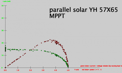
The red dots are obtained multiplying the voltage (x axis) by the current at this voltage, green dots.
You can see that the maximum voltage for this cell, around 5V, is not generating the maximum power, which is at 3.8V.
WIth the load (resistance) in the circuit, you have to keep the cell at this maximum power point.
- Measuring the MPPT graph
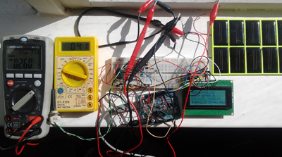
Measuring the MPPT relation is not simple in practice. You need to insert the cell in a circuit in which you can vary the resistance. You need to measure the current and the voltage around the solar cell. You have to register the Voltage and the Current depending on the resistance in the circuit varied with a potmeter. Than you multiply the current and the resistance to get the power and plot the values as function of the voltage.
I solved this by using an Arduino, the analog PIN can measure voltages up to 5.0V. The current was measured using a shunt and over this shunt a Instrumental Amplifier [3]. This value can also be recorded with an analog PIN of the Arduino.
The values measured were send to a Processing Sketch which produces the graph of all the values, while you turn the potmeter.
Github Script
Energy Harvesting Chips
For harvesting there are many different situations and domains. For many of these domains Linear Technology has specialized chips.
We have used two of these:
   piezo harvesting (buck circuit) LTC3588

   solar harvesting (boost circuit) LTC3105
- Buck1: LTC3588: This circuit takes care of positive/negative varying voltage input (piezo).
For the connaisseur: this LTC3588 is a buck circuit (not a boost) because the Piezo produces lots of Volts (eg 14V). These Volts must be DC-DC-ed downwards to 3.3V.
I bought the LTC3588 from Farnell, but I had to solder the connections with a magnifying glass. You need an inductor and some capacitors to go with it.
You can also buy it at Sparkfun on a board: [4]
The chip can be used to harvest energy to a certain point, at which a microcontroller can be waked up from sleep mode. Then you have a bit of energy to do something before going into sleep mode again. You can send a sensor value with a transceiver for example.
This is a movie where a LED is on after waking up, then going to sleep again:
[5]
- Boost: LTC3105, for solar cell's
This IC takes care of the nuisance of clouds in front of the Sun: once started it stays on producing the set voltage between 1.2 and 7V by using a boost circuit. MPPT is functioning on a preset voltage. There is also power to feed a Attiny85.
(MPPT stands for Maximum Power Point Tracking and tries to reach the optimal energy point in exploiting solar cells.
This is an important video explaing the use of the harvesting MPPT IC’s: [6]
You cannot buy this chip at Sparkfun’s. I bought it at farnell:
[7]
, like the ltc3588, and i have soldered it using a magnifying glass and made my own board:(again, add one inductor and a few caps, besides two potmeters)
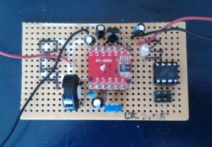
as you can see there is an attiny85 attached which can indicated if the power provided is sufficient for the chip to function (amongst others).
Page with all the harvesting chips from Linear technology:
[8]
Applications
The applications of solar cells relevant for this research are:
- Devices with small solar cells.
wakawaka light for mothers promoted by the ASN bank
- Gadgets with solar cells.
- Wearables, fashion with solar cells.
- Games with solar cells.
- Experimenting kits with solar cells.
Experiments
You have to experiment with solar cells before using one in your project. The differences between solar cells are big: power, voltage and current can range enormously.
The solar cell is not a battery and has to be placed in a circuit which takes care of its particularities, voltage and load. Chaining cells in series can be a problem.
Example 1
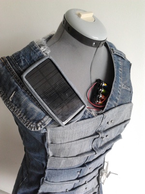
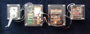
As the result of this research a silhouet was made with an energy game. The wearer charges a supercap with a hand crank charger and at the same time the solar cell charges comparable supercap's.
Documentation about this example will be given on another page: [9]

Example 2
This flexible solar cell:
[10] delivers a huge current 1.5A at a low Voltage: 0.5V (0.75W).
So to reach 5V you need 10 of these, making it very expensive: 80 euro's. Can you buy 3, deliver 1.5V and boost this up to 5V with an LTC chip?
We looked at the LTC3105. It can even start at 250mV, so even one of these panels is enough. But the peek current of this chip is 500mA. Normally 100mA. The power law is P = V.I, so if V goes from 0.5 to 5 the I will go from 1500mA to 150mA (at maximum rendement). So maybe it matches. Experiment!
This solar cell is interesting for the silhouet of example 1, see above. The solar cell used there is solid and sticks out. Flexible cells could be blended into the shape. At the same time these cells curve and might be catching more sunlight. The structure is a lens around the silicium cell, so also this contributes to the optimization of catching of sunlight.
On the other hand, it is clear that 10 of these cells is impossible. One or two requires even an extra LTC3105 chip, making the technology of this silhouet even more complicated.