Difference between revisions of "TB6612 Motor Driver"
| (9 intermediate revisions by the same user not shown) | |||
| Line 1: | Line 1: | ||
| − | [[File: | + | [[File:Tb6612pic.jpg|500px|frameless|none]] |
| + | |||
[https://learn.adafruit.com/adafruit-tb6612-h-bridge-dc-stepper-motor-driver-breakout/overview Here is an overview of this driver :)]<br> | [https://learn.adafruit.com/adafruit-tb6612-h-bridge-dc-stepper-motor-driver-breakout/overview Here is an overview of this driver :)]<br> | ||
You can use this driver to control 1 stepper motor or 2 dc motors.<br> | You can use this driver to control 1 stepper motor or 2 dc motors.<br> | ||
| Line 6: | Line 7: | ||
==Driving Stepper Motors== | ==Driving Stepper Motors== | ||
===Components=== | ===Components=== | ||
| + | *Stepper Motor | ||
*Arduino board (we are using the Uno in this example)<br> | *Arduino board (we are using the Uno in this example)<br> | ||
*TB6612 Motor Driver <br> | *TB6612 Motor Driver <br> | ||
| Line 13: | Line 15: | ||
The amount of power depends on the specifcs of your motor. At the station we have switching power supplies for this purpose. <br> | The amount of power depends on the specifcs of your motor. At the station we have switching power supplies for this purpose. <br> | ||
===Wiring=== | ===Wiring=== | ||
| − | [[File: | + | [[File:Tb6612stepperpic.jpg|500px|frameless|none]] |
*Place your motor driver on the breadboard<br> | *Place your motor driver on the breadboard<br> | ||
*Connect the Pins of the Motor Driver to the ones on the Arduino: | *Connect the Pins of the Motor Driver to the ones on the Arduino: | ||
| Line 38: | Line 40: | ||
-->Motor A to one of the coils | -->Motor A to one of the coils | ||
-->Motor B to the other coil | -->Motor B to the other coil | ||
| + | |||
===Coding=== | ===Coding=== | ||
*Open the Arduino IDE on your computer | *Open the Arduino IDE on your computer | ||
| Line 73: | Line 76: | ||
</syntaxhighlight> | </syntaxhighlight> | ||
| + | |||
==Driving DC Motors== | ==Driving DC Motors== | ||
| + | ===Components=== | ||
| + | * 2x DC motors | ||
| + | *Arduino board (we are using the Uno in this example)<br> | ||
| + | *TB6612 Motor Driver <br> | ||
| + | *Breadboard | ||
| + | *Jumper Wires <br> | ||
| + | *External Power Supply if needed by the motor<br> | ||
| + | ===Wiring=== | ||
| + | [[File:TB6612DCmotors.jpg|500px|frameless]] | ||
| + | -->PWMA to Digital 3 | ||
| + | -->AIN1 to Digital 4 | ||
| + | -->AIN2 to Digital 5 | ||
| + | -->STBY to Digital 9 | ||
| + | -->BIN1 to Digital 7 | ||
| + | -->BIN2 to Digital 8 | ||
| + | -->PWMB to Digital 6 | ||
| + | -->Vcc to 5V | ||
| + | -->GND to ground | ||
| + | -->VM to 5V (or Vin Pin if you need to power the motor with an external power supply) | ||
| + | |||
| + | In this case we are powering the motor with the 5V of the Arduino because it is enough to power our motors. If your motors need 12v you can connect the VM to the Vin Pin on the Arduino. This pin is connected to the DC connector of your board. You can supply the eternal 12 volt power here form your power supply. This will be used to power the Arduino as well. Alternatively, you can connect your external power supply to the green screw terminals on the Motor Driver. They have a + and - connection that can go directly to your power supply. <br> | ||
| + | |||
| + | ===Coding=== | ||
| + | *Open the Arduino IDE on your computer | ||
| + | *Make sure your board is connected and the right port is selected | ||
| + | *Upload the code | ||
| + | <syntaxhighlight lang="c"> | ||
| + | // Define motor control pins | ||
| + | const int PWMA = 3; | ||
| + | const int AIN1 = 4; | ||
| + | const int AIN2 = 5; | ||
| + | const int PWMB = 6; | ||
| + | const int BIN1 = 7; | ||
| + | const int BIN2 = 8; | ||
| + | const int STBY = 9; | ||
| + | |||
| + | void setup() { | ||
| + | // Set all the motor control pins to outputs | ||
| + | pinMode(PWMA, OUTPUT); | ||
| + | pinMode(AIN1, OUTPUT); | ||
| + | pinMode(AIN2, OUTPUT); | ||
| + | pinMode(PWMB, OUTPUT); | ||
| + | pinMode(BIN1, OUTPUT); | ||
| + | pinMode(BIN2, OUTPUT); | ||
| + | pinMode(STBY, OUTPUT); | ||
| + | |||
| + | // Disable standby | ||
| + | digitalWrite(STBY, HIGH); | ||
| + | } | ||
| + | |||
| + | void loop() { | ||
| + | // Drive motor A forward | ||
| + | digitalWrite(AIN1, HIGH); | ||
| + | digitalWrite(AIN2, LOW); | ||
| + | analogWrite(PWMA, 255); // Full speed | ||
| + | |||
| + | // Drive motor B forward | ||
| + | digitalWrite(BIN1, HIGH); | ||
| + | digitalWrite(BIN2, LOW); | ||
| + | analogWrite(PWMB, 255); // Full speed | ||
| + | |||
| + | delay(2000); // Run for 2 seconds | ||
| + | |||
| + | // Stop motors | ||
| + | analogWrite(PWMA, 0); | ||
| + | analogWrite(PWMB, 0); | ||
| + | |||
| + | delay(1000); // Stop for 1 second | ||
| + | |||
| + | // Drive motor A backward | ||
| + | digitalWrite(AIN1, LOW); | ||
| + | digitalWrite(AIN2, HIGH); | ||
| + | analogWrite(PWMA, 255); // Full speed | ||
| + | |||
| + | // Drive motor B backward | ||
| + | digitalWrite(BIN1, LOW); | ||
| + | digitalWrite(BIN2, HIGH); | ||
| + | analogWrite(PWMB, 255); // Full speed | ||
| + | |||
| + | delay(2000); // Run for 2 seconds | ||
| + | |||
| + | // Stop motors | ||
| + | analogWrite(PWMA, 0); | ||
| + | analogWrite(PWMB, 0); | ||
| + | |||
| + | delay(1000); // Stop for 1 second | ||
| + | } | ||
| + | </syntaxhighlight> | ||
| + | |||
| + | [[Category:Motors]][[Category:Arduino]] | ||
Latest revision as of 08:50, 11 October 2024
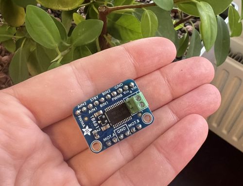
Here is an overview of this driver :)
You can use this driver to control 1 stepper motor or 2 dc motors.
This driver is available for use at the Station.
Driving Stepper Motors
Components
- Stepper Motor
- Arduino board (we are using the Uno in this example)
- TB6612 Motor Driver
- Breadboard
- Jumper Wires
- External Power Supply
The amount of power depends on the specifcs of your motor. At the station we have switching power supplies for this purpose.
Wiring
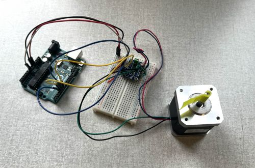
- Place your motor driver on the breadboard
- Connect the Pins of the Motor Driver to the ones on the Arduino:
-->VM to Vin Pin
-->Vcc to 5V
-->GND to ground
-->AIN2 to Digital 4
-->AIN1 to Digital 5
-->BIN1 to Digital 6
-->BIN2 to Digital 7
-->PWMA and PWMB to 5V
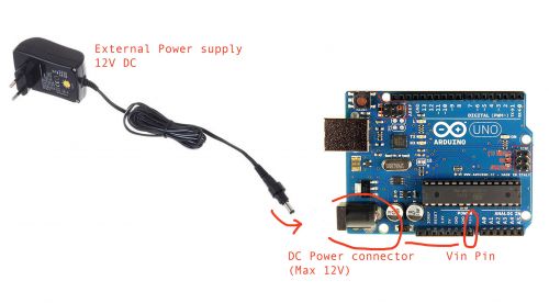
In this case we are powering the motor with the Vin Pin of the Arduino. The pin is connected to the DC connector. You can supply the eternal 12 volt power here form your power supply. This will be used to power the Arduino as well. Alternatively, you can connect your external power supply to the green screw terminals on the Motor Driver. They have a + and - connection that can go directly to your power supply.
- Connect the Motor to the Motor Driver
Your stepper motor, accordingly to the type, will most likely have 4 wires. Some of them can also have 5 or 6. On the motor driver you see that you have 2 pin conenctions for Motor A and two for Motor B. To figure out which one of the wires of the motor goes where you need to understand which one of the pair of wires is coil A and coil B of the motor.
If you don't know you can check this with a multimeter. Follow this video to see how. If you are working with a stepper motor with more than 4 wires you will see that it will have still two pair of wires that are the two coils. The extra wire(s) can be ignored.
Here's a scheme of common wire connections id you don't have a multimeter to check the coils.
You have now determined the two pairs of wire to connect to the motor driver. Each pair will be connected to the Motor A and Motor B pins on the driver.
-->Motor A to one of the coils
-->Motor B to the other coil
Coding
- Open the Arduino IDE on your computer
- Make sure your board is connected and the right port is selected
- Upload the code
For this basic test we are using the in build Arduino Stepper library.
#include <Stepper.h>

// change this to the number of steps on your motor
#define STEPS 200

// create an instance of the stepper class, specifying
// the number of steps of the motor and the pins it's
// attached to
Stepper stepper(STEPS, 4, 5, 6, 7);


void setup()
{
  Serial.begin(9600);
  Serial.println("Stepper test!");
  // set the speed of the motor to 30 RPMs
  stepper.setSpeed(60);
}

void loop()
{
  Serial.println("Forward");
  stepper.step(STEPS);
  Serial.println("Backward");
  stepper.step(-STEPS);
}
Driving DC Motors
Components
- 2x DC motors
- Arduino board (we are using the Uno in this example)
- TB6612 Motor Driver
- Breadboard
- Jumper Wires
- External Power Supply if needed by the motor
Wiring
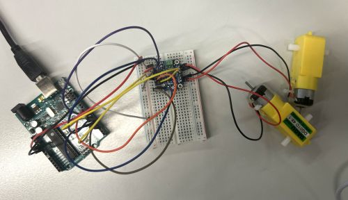
-->PWMA to Digital 3
-->AIN1 to Digital 4
-->AIN2 to Digital 5
-->STBY to Digital 9
-->BIN1 to Digital 7
-->BIN2 to Digital 8
-->PWMB to Digital 6
-->Vcc to 5V
-->GND to ground
-->VM to 5V (or Vin Pin if you need to power the motor with an external power supply)
In this case we are powering the motor with the 5V of the Arduino because it is enough to power our motors. If your motors need 12v you can connect the VM to the Vin Pin on the Arduino. This pin is connected to the DC connector of your board. You can supply the eternal 12 volt power here form your power supply. This will be used to power the Arduino as well. Alternatively, you can connect your external power supply to the green screw terminals on the Motor Driver. They have a + and - connection that can go directly to your power supply.
Coding
- Open the Arduino IDE on your computer
- Make sure your board is connected and the right port is selected
- Upload the code
// Define motor control pins
const int PWMA = 3;
const int AIN1 = 4;
const int AIN2 = 5;
const int PWMB = 6;
const int BIN1 = 7;
const int BIN2 = 8;
const int STBY = 9;

void setup() {
  // Set all the motor control pins to outputs
  pinMode(PWMA, OUTPUT);
  pinMode(AIN1, OUTPUT);
  pinMode(AIN2, OUTPUT);
  pinMode(PWMB, OUTPUT);
  pinMode(BIN1, OUTPUT);
  pinMode(BIN2, OUTPUT);
  pinMode(STBY, OUTPUT);

  // Disable standby
  digitalWrite(STBY, HIGH);
}

void loop() {
  // Drive motor A forward
  digitalWrite(AIN1, HIGH);
  digitalWrite(AIN2, LOW);
  analogWrite(PWMA, 255); // Full speed

  // Drive motor B forward
  digitalWrite(BIN1, HIGH);
  digitalWrite(BIN2, LOW);
  analogWrite(PWMB, 255); // Full speed

  delay(2000); // Run for 2 seconds

  // Stop motors
  analogWrite(PWMA, 0);
  analogWrite(PWMB, 0);

  delay(1000); // Stop for 1 second

  // Drive motor A backward
  digitalWrite(AIN1, LOW);
  digitalWrite(AIN2, HIGH);
  analogWrite(PWMA, 255); // Full speed

  // Drive motor B backward
  digitalWrite(BIN1, LOW);
  digitalWrite(BIN2, HIGH);
  analogWrite(PWMB, 255); // Full speed

  delay(2000); // Run for 2 seconds

  // Stop motors
  analogWrite(PWMA, 0);
  analogWrite(PWMB, 0);

  delay(1000); // Stop for 1 second
}


