Difference between revisions of "Arduino & Relays"
(Created page with "The Conrad relay modules in the Station require higher that 5V voltage to operate, so we will use a 9V battery as a power source and switch it with an Arduino trough a BC547 t...") |
(→Wiring) |
||
| (6 intermediate revisions by the same user not shown) | |||
| Line 1: | Line 1: | ||
| + | |||
| + | ==Introducing the Relay Module== | ||
| + | |||
| + | [[File:Relay02.jpg| 400 px]] | ||
| + | |||
| + | A relay is an electrically operated switch of mains voltage. It means that it can be turned on or off, letting the current go through or not. | ||
| + | |||
| + | ==Controlling a relay module with Arduino== | ||
| + | Controlling a relay with the Arduino is as simple as controlling an output such as an LED. | ||
| + | |||
| + | '''Notice the writing on the module terminals'''<br> | ||
| + | |||
| + | '''COM''': common pin<br> | ||
| + | '''NO''' (Normally Open): There is no contact between the common pin and the normally open pin. So, when you trigger the relay, it connects to the COM pin and supply is provided to a load<br> | ||
| + | '''NC''' (Normally Closed): There is contact between the common pin and the normally closed pin. There is always connection between the COM and NC pins, even when the relay is turned off. When you trigger the relay, the circuit is opened and there is no supply provided to a load.<br> | ||
| + | If you want to control a lamp for example, it is better to use a normally-open circuit, because we just want to light up the lamp occasionally. | ||
| + | |||
| + | ===Wiring=== | ||
| + | [[File:relay_wiring.png|500px]] | ||
| + | <br> | ||
| + | It is very straightforward as you can see. But always double-check the relay module connections before you plug things together. <br> | ||
| + | '''COM''' goes to the power supply/mains<br> | ||
| + | '''NO''' goes to your device<br> | ||
| + | Arduino connection:<br> | ||
| + | '''GND''' or '''DC-''' goes to ground<br> | ||
| + | '''VCC''' or '''DC+''' goes to 5V <br> | ||
| + | '''IN''': goes to a digital pin (you can pick the one you prefer)<br> | ||
| + | |||
| + | '''OK, but maybe you want to control more than one thing??''' | ||
| + | <br> Then no problem:<br> | ||
| + | [[File:6-Channel-12V-Relay-Module.jpg]]<br> | ||
| + | Here are 16 channels:)<br> | ||
| + | You can easily find Relay modules with different amounts of channels, accordingly to your needs. | ||
| + | Wiring is the same, you will just need 16 digital pins on the Arduino | ||
| + | |||
| + | ===Conrad Relay Modules=== | ||
| + | |||
The Conrad relay modules in the Station require higher that 5V voltage to operate, so we will use a 9V battery as a power source and switch it with an Arduino trough a BC547 transistor. | The Conrad relay modules in the Station require higher that 5V voltage to operate, so we will use a 9V battery as a power source and switch it with an Arduino trough a BC547 transistor. | ||
<br> | <br> | ||
| − | The modules look like this | + | The modules look like this:<br> |
| − | [[File:Relay modules.jpg | | + | [[File:Relay modules.jpg | 600 px]]<br> |
| − | <br> On the printed pcb modules there is a small separate circuit, where the transistor is. | + | <br>On the printed pcb modules there is a small separate circuit, where the transistor is. |
| − | <br> | + | <br>The small circuit looks like this in detail:<br> |
| − | [[File:Relay addon.jpg | | + | [[File:Relay addon.jpg | 600 px]] <br> |
| − | This is the BC547 pinout | + | This is the BC547 pinout:<br> |
| − | [[File:BC547.jpg]]<br> | + | [[File:BC547.jpg| 600 px]]<br> |
The Arduino is connected trough a resistor to the Base of the Transistor. | The Arduino is connected trough a resistor to the Base of the Transistor. | ||
| − | + | So the signal is to be connected onto the pin that is next to the resistor (look above) | |
<br> | <br> | ||
When the Arduino pin is High, then voltage flows from the Emitter to the Collector, therefore it switches the relay on trough the battery. | When the Arduino pin is High, then voltage flows from the Emitter to the Collector, therefore it switches the relay on trough the battery. | ||
<br> | <br> | ||
| − | There are some boards that are not printed PCBs. They look like this | + | There are some boards that are not printed PCBs. They look like this: |
<br> | <br> | ||
| − | [[File:Relay diy01.jpg | | + | [[File:Relay diy01.jpg | 600 px]] |
<br> | <br> | ||
The transistor is placed directly on the board in this case. The logic is the same. Looks like this (always check the resistor from the Base, the pin it is connected to is the Arduino pin) | The transistor is placed directly on the board in this case. The logic is the same. Looks like this (always check the resistor from the Base, the pin it is connected to is the Arduino pin) | ||
| − | <br>[[File:Relay diy02.jpg | | + | <br>[[File:Relay diy02.jpg | 600 px]] |
| + | |||
| + | [[Category:Arduino]] | ||
Latest revision as of 17:00, 14 March 2023
Introducing the Relay Module
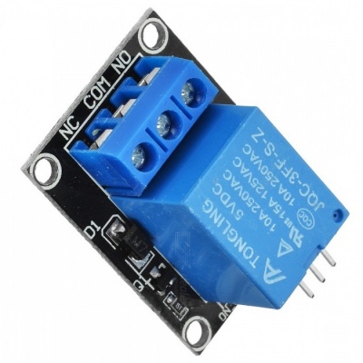
A relay is an electrically operated switch of mains voltage. It means that it can be turned on or off, letting the current go through or not.
Controlling a relay module with Arduino
Controlling a relay with the Arduino is as simple as controlling an output such as an LED.
Notice the writing on the module terminals
COM: common pin
NO (Normally Open): There is no contact between the common pin and the normally open pin. So, when you trigger the relay, it connects to the COM pin and supply is provided to a load
NC (Normally Closed): There is contact between the common pin and the normally closed pin. There is always connection between the COM and NC pins, even when the relay is turned off. When you trigger the relay, the circuit is opened and there is no supply provided to a load.
If you want to control a lamp for example, it is better to use a normally-open circuit, because we just want to light up the lamp occasionally.
Wiring
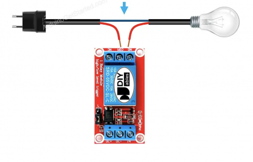
It is very straightforward as you can see. But always double-check the relay module connections before you plug things together.
COM goes to the power supply/mains
NO goes to your device
Arduino connection:
GND or DC- goes to ground
VCC or DC+ goes to 5V
IN: goes to a digital pin (you can pick the one you prefer)
OK, but maybe you want to control more than one thing??
Then no problem:
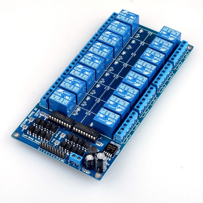
Here are 16 channels:)
You can easily find Relay modules with different amounts of channels, accordingly to your needs.
Wiring is the same, you will just need 16 digital pins on the Arduino
Conrad Relay Modules
The Conrad relay modules in the Station require higher that 5V voltage to operate, so we will use a 9V battery as a power source and switch it with an Arduino trough a BC547 transistor.
The modules look like this:
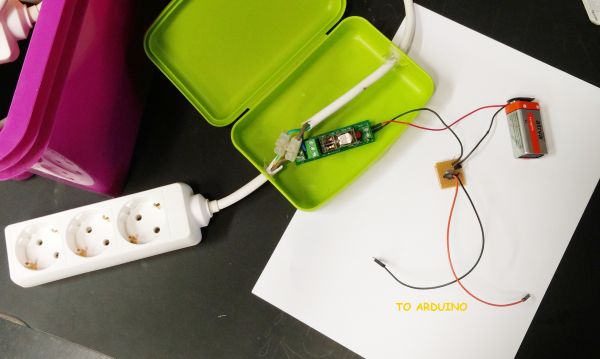
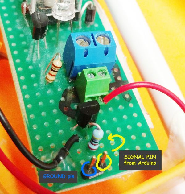
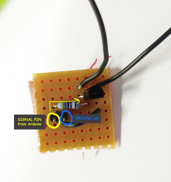
On the printed pcb modules there is a small separate circuit, where the transistor is.
The small circuit looks like this in detail:
This is the BC547 pinout:
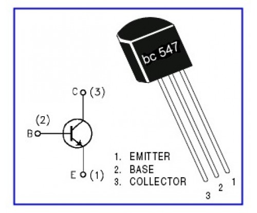
The Arduino is connected trough a resistor to the Base of the Transistor.
So the signal is to be connected onto the pin that is next to the resistor (look above)
When the Arduino pin is High, then voltage flows from the Emitter to the Collector, therefore it switches the relay on trough the battery.
There are some boards that are not printed PCBs. They look like this:
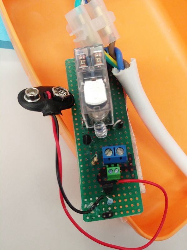
The transistor is placed directly on the board in this case. The logic is the same. Looks like this (always check the resistor from the Base, the pin it is connected to is the Arduino pin)
