Difference between revisions of "Arduino & Pure Data"
Jump to navigation
Jump to search
m (Annasa moved page Arduino & Pure Data communications to Arduino & Pure Data) |
|||
| (3 intermediate revisions by the same user not shown) | |||
| Line 1: | Line 1: | ||
| − | + | This page will explain how to set up communications between pure data and Arduino. | |
| Line 45: | Line 45: | ||
This circuit diagram use Arduino pin 7, if you use the example Pure Data patch, you need to either change the pin number in PD or change the circuit a little. | This circuit diagram use Arduino pin 7, if you use the example Pure Data patch, you need to either change the pin number in PD or change the circuit a little. | ||
| + | |||
| + | [[Category:Arduino]][[Category:Pure Data]] | ||
Latest revision as of 11:44, 13 January 2023
This page will explain how to set up communications between pure data and Arduino.
Pure Data write to Arduino:
1. Arduino:
open Arduino example firmata --- upload StanderFirmata.
and that's it! the Arduino coding part is done!
2. Pure Data:
we will need to install some externals: 1. Pduino: https://puredata.info/downloads/pduino 2. if some other externals are missing you can install them via PD's help window - find externals. there is the patch that allows you to write to Arduino both in PWM and digital:in this patch, we are writing to Arduino Uno pin 11, it is a PWM pin. connect your Arduino via a USB to your computer Click on "devices" to check the Arduino port number, in my case, it is port 4. that's why after the message "open" I type "open 4". you need to change the number according to your own USB port. connect a LED between pin 11 and Ground. now, we click on "pinMode 11 output" and if we now click on "digital 11 1" we will turn on pin 11, and "digital 11 0" turns it off. if you want to dim the LED you need to use PWM. Click on "pinMode 11 pwm" to enable PWM, and move around the yellow slider(value between 0-1), you can dim the LED now. if you want to switch to digital output click "pwm 11 off".
3. extra hardware:
  now we learned how to control an led, we can also add some components and create a circuit to control heavy-duty motors or even devices running on 220v AC.
  we will use digital output options from the PD patch ("digital 11 1" "digital 11 0") to control the motor and an AC light bulb(also can be an electric fan).

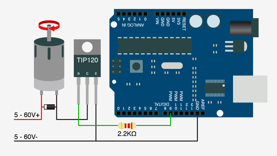
  First, we take a look at how to use Tip 120 transistor to control DC motors:
This circuit diagram use Arduino pin 9, if you use the example Pure Data patch, you need to either change the pin number in PD or change the circuit a little.
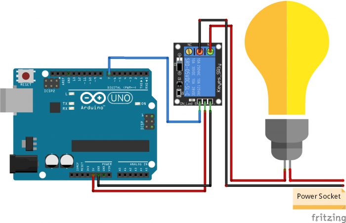
now we can also turn on and off a 220v AC device via a relay.
This circuit diagram use Arduino pin 7, if you use the example Pure Data patch, you need to either change the pin number in PD or change the circuit a little.

