Difference between revisions of "Trans/humanism/formationdesign"
| Line 264: | Line 264: | ||
</syntaxhighlight> | </syntaxhighlight> | ||
| + | <br> | ||
| + | Some calibration | ||
| + | <br> | ||
| + | <syntaxhighlight lang=c style="border:3px dashed pink"> | ||
| + | |||
| + | #include <Servo.h> | ||
| + | |||
| + | |||
| + | // These constants won't change: | ||
| + | const int sensorPin = A0; // pin that the sensor is attached to | ||
| + | Servo myservo; // create servo object to control a servo | ||
| + | |||
| + | // variables: | ||
| + | int sensorValue = 0; // the sensor value | ||
| + | int sensorMin = 1023; // minimum sensor value | ||
| + | int sensorMax = 0; // maximum sensor value | ||
| + | |||
| + | void setup() { | ||
| + | Serial.begin(9600); | ||
| + | myservo.attach(10); // attaches the servo on pin 8 to the servo object | ||
| + | |||
| + | // turn on LED to signal the start of the calibration period: | ||
| + | pinMode(13, OUTPUT); | ||
| + | digitalWrite(13, HIGH); | ||
| + | |||
| + | // calibrate during the first five seconds | ||
| + | while (millis() < 5000) { | ||
| + | sensorValue = analogRead(sensorPin); | ||
| + | |||
| + | // record the maximum sensor value | ||
| + | if (sensorValue > sensorMax) { | ||
| + | sensorMax = sensorValue; | ||
| + | } | ||
| + | |||
| + | // record the minimum sensor value | ||
| + | if (sensorValue < sensorMin) { | ||
| + | sensorMin = sensorValue; | ||
| + | } | ||
| + | } | ||
| + | } | ||
| + | |||
| + | |||
| + | |||
| + | void loop() { | ||
| + | |||
| + | |||
| + | // read the sensor: | ||
| + | sensorValue = analogRead(sensorPin); | ||
| + | |||
| + | // apply the calibration to the sensor reading | ||
| + | sensorValue = map(sensorValue, sensorMin, sensorMax, 0, 180); | ||
| + | |||
| + | // in case the sensor value is outside the range seen during calibration | ||
| + | sensorValue = constrain(sensorValue, 0, 180); | ||
| + | |||
| + | // fade the LED using the calibrated value: | ||
| + | Serial.println(sensorValue); | ||
| + | myservo.write(sensorValue);// sets the servo position according to the scaled value | ||
| + | |||
| + | delay(5); // waits for the servo to get there | ||
| + | |||
| + | } | ||
| + | |||
| + | </syntaxhighlight> | ||
| + | |||
=week 2 <br><br>''The Virual Body / (dis)emodiment in VR''= | =week 2 <br><br>''The Virual Body / (dis)emodiment in VR''= | ||
Revision as of 22:08, 7 February 2018
week 1
Breathe in, breathe out
Special guest: Gillian Baldwin from the Piet Zwart Institute to talk about her respiratory harness
what is the Arduino
Hello everyone hello hello hello,
now what is an Arduino ...well...find a detailed introduction here [[1]]
Computer and processor are generic terms for the anything that can run a program, basically.
Controller or microcontroller usually refers to a simple processor that does only one task, like listening to sensors. In explaining microcontrollers, we’ll distinguish them from computers, which contain more powerful processors that can run an operating system.
Arduino is an open source physical computing platform based on a simple input/output (I/O) board and a development environment that implements the Processing language. Arduino can be used to develop standalone interactive objects
or can be connected to software on your computer.
The Arduino contains a microcontroller.
Most electronic devices today have a microcontroller at their core. Microcontrollers are optimized for control of general input and output.
What Is Physical Computing?
Physical Computing uses electronics to prototype new materials for ( in our case ) designers and artists.
Arduino is composed of two major parts: the Arduino board, which is the piece of hardware you work on when you build your objects; and the Arduino IDE, the piece of software you run on your computer. You use the IDE to create
a sketch (a little computer program) that you upload to the Arduino board. The sketch tells the board what to do.
In the meantime, HERE you can find ANYTHING about Arduino, including download the software
NOW,
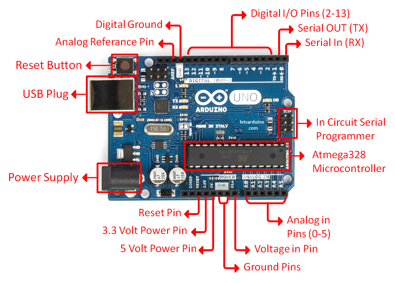
The pins on your Arduino are the places where you connect wires to construct a circuit (probably in conjunction with a breadboard and some wire. They usually have black plastic ‘headers’ that allow you to just plug a wire right into the board. The Arduino has several different kinds of pins, each of which is labeled on the board and used for different functions.
First things first
we start by figuring put if our Arduino is all good or it is somehow damaged ...it is a basic test to check and run a simple script at the same time.
Go to File ---> Examples ---> Basics --->Blink
so we have something like this
/*
  Blink
  Turns on an LED on for one second, then off for one second, repeatedly.

  Most Arduinos have an on-board LED you can control. On the Uno and
  Leonardo, it is attached to digital pin 13. If you're unsure what
  pin the on-board LED is connected to on your Arduino model, check
  the documentation at http://www.arduino.cc

  This example code is in the public domain.

  modified 8 May 2014
  by Scott Fitzgerald
 */


// the setup function runs once when you press reset or power the board
void setup() {
  // initialize digital pin 13 as an output.
  pinMode(13, OUTPUT);
}

// the loop function runs over and over again forever
void loop() {
  digitalWrite(13, HIGH);   // turn the LED on (HIGH is the voltage level)
  delay(1000);              // wait for a second
  digitalWrite(13, LOW);    // turn the LED off by making the voltage LOW
  delay(1000);              // wait for a second
}
GOOOD! lets dissect this
- commenting / one line and multiple lines
- setup
- loop
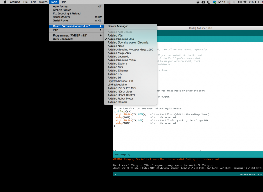
Choose board
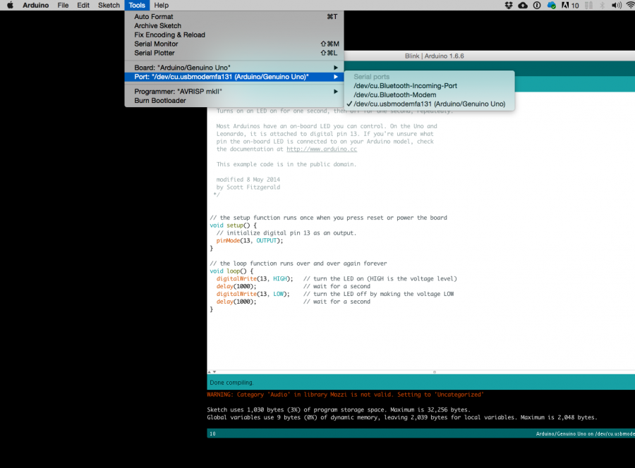
Choose port
Lets compile this
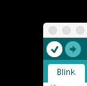
--- Press/ Click upper most left button, looks like a Tick. Observe the messages appearing in the bottom of the Arduino software window ( there must be a sentence Done Compiling
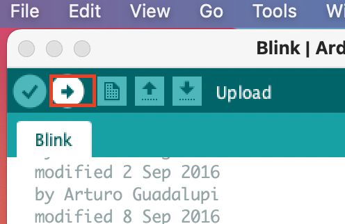
Lets upload this
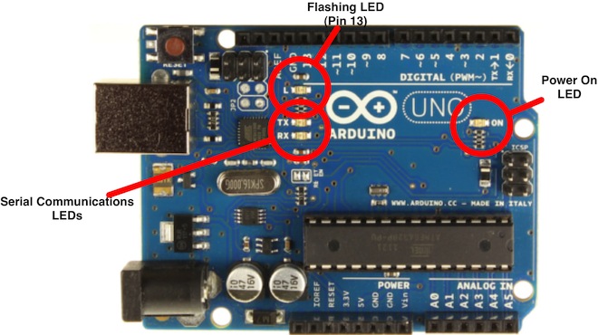
And we should have a Blinking aka Flashing on board LED
Inputs and Outputs
Like mentioned earlier - μControllers are optimized for control of general input and output. What are those two exactly.
Analog ( we have six of them in the Uno): The area of pins under the ‘Analog In’ label (A0 through A5 on the UNO) are Analog In pins. These pins can read the signal from an analog sensor (like a temperature sensor) and convert it into a digital value that we can read.
Digital (seven on the Uno): Across from the analog pins are the digital pins (0 through 13 on the UNO). These pins can be used for both digital input (like telling if a button is pushed) and digital output (like powering an LED).
Sensors
Digital Sensors
Digital sensors are the sensors that gives 2 state (on/off, 5V/0V). You will connect them to digital Pins and set it as INPUT.
Digital data consists exclusively of 0s and 1s .
For example, consider a push button switch. This is one of the simplest forms of sensors. It has two discrete values. It is on, or it is off. Other 'discrete' sensors might provide you with a binary value.
Another example of a digital sensor is an accelerometer, which sends a series of data points (speed, direction, and so on) to the Arduino. Usually digital sensors need a chip in the sensor to interpret the physical data.
Analog Sensors
Analog sensors on the other hand, gives range. You connect this types of Analog sensors to Analog Input pins which is measuring the incoming voltage between 0V-5V*. Arduino converts this incoming voltage into the number between 0-1023.
Analog data is transmitted as a continuous signal, almost like a wave. In other words, an analog sensor doesn’t send a burst of 1s and 0s like digital sensors do; instead, the sensor modulates a continuous signal to transmit data.
Microcontrollers are capable of detecting binary signals: is the button pressed or not? These are digital signals. When a microcontroller is powered from five volts, it understands zero volts (0V) as a binary 0 and a five volts (5V) as a binary 1. The world however is not so simple and likes to use shades of gray. What if the signal is 2.72V? Is that a zero or a one? We often need to measure signals that vary; these are called analog signals. A 5V analog sensor may output 0.01V or 4.99V or anything inbetween. Luckily, nearly all microcontrollers have a device built into them that allows us to convert these voltages into values that we can use in a program to make a decision.
An Analog to Digital Converter (ADC) is a very useful feature that converts an analog voltage on a pin to a digital number. By converting from the analog world to the digital world, we can begin to use electronics to interface to the analog world around us.
Not every pin on a microcontroller has the ability to do analog to digital conversions. On the Arduino board, these pins have an ‘A’ in front of their label (A0 through A5) to indicate these pins can read analog voltages.
ADCs can vary greatly between microcontroller. The ADC on the Arduino is a 10-bit ADC meaning it has the ability to detect 1,024 (210) discrete analog levels. Some microcontrollers have 8-bit ADCs (28 = 256 discrete levels) and some have 16-bit ADCs (216 = 65,536 discrete levels).
case study: Stretch Sensor
As a main actor of today we will take the conductive rubber.
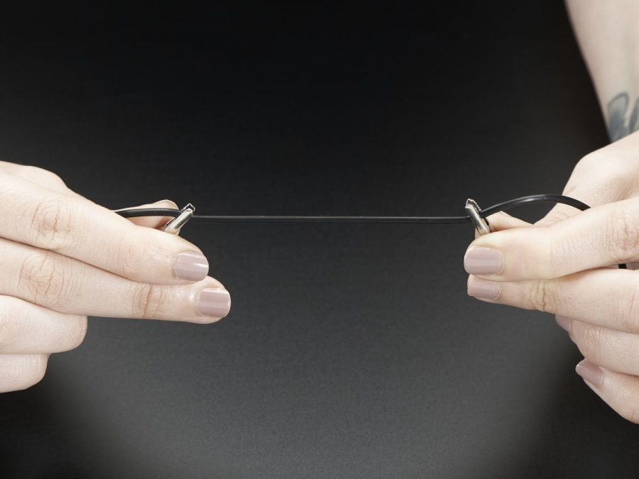
Hooked up to two alligator clips we create a simple resistive sensor.
Analog Voltage Reading Method
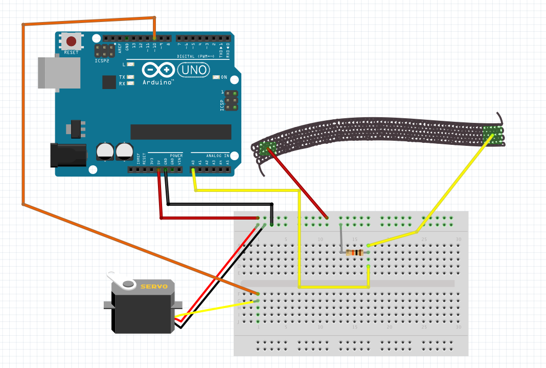
The easiest way to measure a resistive sensor is to connect one end to Power and the other to a pull-down resistor to ground. Then the point between the fixed pulldown resistor and the variable resistor ( conductive rubber) is connected to the analog input of a microcontroller such as the Arduino.
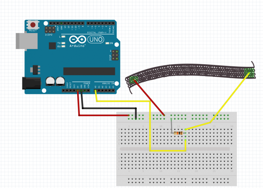
OK, wait...the BREADBOARD
OK, first, what's with the name....bread board? Bread, like in food?
Well yes, kind of.
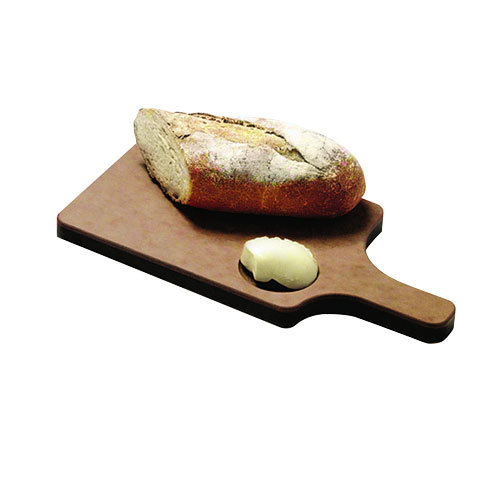
This terminology goes way back in the days.
Generally, you would mount electronic components to a piece of wood (the actual "breadboard"), and do all the wiring with point-point wire and the components just hanging between the various devices.
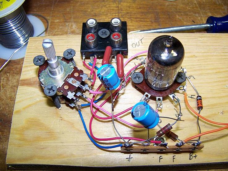
The story goes that an engineer had an idea for a vacuum tube device late one night. Looking around the house, the only base for his prototype that he found was indeed his wife's breadboard, from the breadbox.
A video by the Make magazine people
Ok, but why do we need to breadboard?
Well, they are useful for making temporary circuits and prototyping, and they require absolutely no soldering.
Prototyping is the process of testing out an idea by creating a preliminary model from which other forms are developed or copied, and it is one of the most common uses for breadboards.
The best way to explain how a breadboard works is to take it apart and see what’s inside.
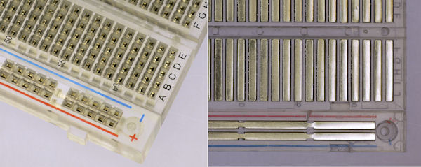
connections lines are connected like this
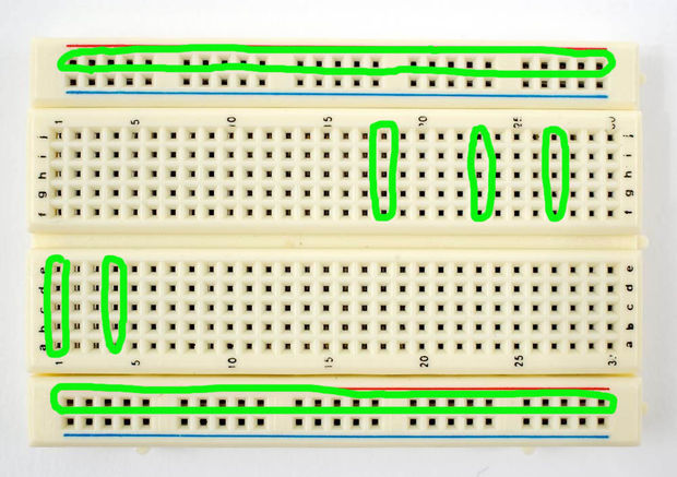
So lets try to
get some data from it
const int sensor= A0;


// the setup runs once when you press reset or start the arduino:
void setup() {
// initialize serial communication at 9600 bits per second:
  Serial.begin(9600);


}

// the loop runs over and over again:
void loop() {
  int sensorValue = analogRead(sensor); // read the voltage from the voltage divider (sensor plus resistor)
  Serial.println (sensorValue); //print the sensorValue into the Serial Monitor
  delay(1);        // delay in between reads for stability

}
It's alive
now lets add an Output
//including the servo library
#include <Servo.h>

Servo myservo;  // create servo object to control a servo
// twelve servo objects can be created on most boards
int val; // variable to read the value from the analog pin

void setup() {


Serial.begin(9600); // initialize serial communication at 9600 bits per second:
myservo.attach(10);  // attaches the servo on pin 10 to the servo object
}

void loop() {

int sensor;
int degrees;
sensor = analogRead(A0); // read the voltage from the voltage divider (sensor plus resistor)

degrees = map(sensor, 77, 60, 0, 90);
// the first two numbers are the sensor values for unstretched and stretched
// the second two numbers are the degree readings we'll map that to (0 to 90 degrees)
// the above numbers are just an example, your sensor's values will vary
// to improve the accuracy, run the program, note your sensor's analog values
// when it's calm and stretched, and insert those values into the above function.

myservo.write(degrees);// sets the servo position according to the scaled value

delay(5); // waits for the servo to get there

//for debug use
// print out the result

Serial.print("analog input: ");
Serial.print(sensor);
Serial.print(" degrees: ");
Serial.println(degrees);

delay(5);// pause before taking the next reading

}
Some calibration
#include <Servo.h>


// These constants won't change:
const int sensorPin = A0;    // pin that the sensor is attached to
Servo myservo;  // create servo object to control a servo

// variables:
int sensorValue = 0;         // the sensor value
int sensorMin = 1023;        // minimum sensor value
int sensorMax = 0;           // maximum sensor value

void setup() {
 Serial.begin(9600);
 myservo.attach(10); // attaches the servo on pin 8 to the servo object

  // turn on LED to signal the start of the calibration period:
  pinMode(13, OUTPUT);
  digitalWrite(13, HIGH);

  // calibrate during the first five seconds
  while (millis() < 5000) {
    sensorValue = analogRead(sensorPin);

    // record the maximum sensor value
    if (sensorValue > sensorMax) {
      sensorMax = sensorValue;
    }

    // record the minimum sensor value
    if (sensorValue < sensorMin) {
      sensorMin = sensorValue;
    }
  }
}


void loop() {


  // read the sensor:
  sensorValue = analogRead(sensorPin);

  // apply the calibration to the sensor reading
  sensorValue = map(sensorValue, sensorMin, sensorMax, 0, 180);

  // in case the sensor value is outside the range seen during calibration
  sensorValue = constrain(sensorValue, 0, 180);

  // fade the LED using the calibrated value:
 Serial.println(sensorValue);
 myservo.write(sensorValue);// sets the servo position according to the scaled value

delay(5); // waits for the servo to get there

}
week 2
The Virual Body / (dis)emodiment in VR
Guest teacher: Brigit Lichtenegger
We will discuss (dis)embodyment in VR
Students will work with 360 degree video. The class will kick off with a short introduction lecture, discussing context and examples, then the students will think of an experiment in 3 groups.
week 3
The hacked body
In this class we will return to the physical body and talk about bodily interventions/extensions/expansions/augmentations. We will be going back to the Arduino and taking our sensor input to make use of it to alter the body, thus we will be attempting a body ‘hack' ( a physically minor and harmless one, of course. But we will try to keep our imagination completely loose of restrictions to aid further ideas.)
week 4
The augmented body
What is the face in a body? How does our face signify us? How is it a control interface? We will look into emotion recognition and machine learning, and how do our emotions affect not only other humans but also machines. We will use the Wekinator, emotion recognition and control some physical outputs.)
