Difference between revisions of "Workshop one"
| Line 58: | Line 58: | ||
[[File:Circuit playground d13.jpeg|400px]] | [[File:Circuit playground d13.jpeg|400px]] | ||
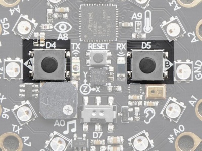
| − | '''3. This small button is for Resetting the board.''' ------------------ '''4. Button A and B on Digital pin#4 and #5''' | + | '''3. This small button is for Resetting the board.''' ------------------ '''4. Button A and B on Digital pin #4 and #5''' |
[[File:Circuit playground reset.jpeg|400px]] | [[File:Circuit playground reset.jpeg|400px]] | ||
[[File:Circuit playground pushbutton.jpeg|400px]] | [[File:Circuit playground pushbutton.jpeg|400px]] | ||
| + | |||
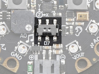
| + | '''5. slide switch on Digital pin #7''' - - - - - - - - - - - - - - - - - - - - - - ''' 6. 7 Capacitive Touch pads from A1-A7''' | ||
[[File:Circuit playground slide.jpeg|400px]] | [[File:Circuit playground slide.jpeg|400px]] | ||
Revision as of 14:32, 31 March 2021
Microcontrollers
Computer and processor are generic terms for anything that can run a program, basically.
A controller or microcontroller usually refers to a simple processor that does only one task, like listening to sensors.
In explaining microcontrollers, we’ll distinguish them from computers, which contain more powerful processors that can run an operating system.
Arduino
what is an Arduino?
Arduino is an open source physical computing platform based on a simple input/output (I/O) board and a development environment that implements the Processing language. Arduino can be used to develop standalone interactive objects
or can be connected to software on your computer.
Arduino is composed of two major parts: the Arduino board, which is the piece of hardware you work on when you build your objects;
and the Arduino IDE, the piece of software you run on your computer. You use the IDE to createa sketch (a little computer program)
that you upload to the Arduino board. The sketch tells the board what to do.
In the meantime, HERE you can find ANYTHING about Arduino, including download the software
find a detailed introduction here [[1]]
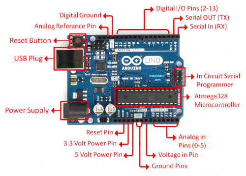
The pins on your Arduino are the places where you connect wires to construct a circuit (probably in conjunction with a breadboard and some wire. They usually have black plastic ‘headers’ that allow you to just plug a wire right into the board. The Arduino has several different kinds of pins, each of which is labeled on the board and used for different functions.
Adafruit Circuit Playground Express
How's that different?
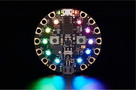
The Circuit Playground Express is also a microcontroller, produced by Adafruit, just like the Arduino Uno, however, it includes a bunch of build-in sensors to detect motion, temperature, light, and infrared light, and also has neopixel lights, and mini speakers. Circuit Playground Express can be programmed using Arduino IDE, CircuitPython, and Microsoft MakeCode.
On the hardware side, Circuit Playground Express(we call it CPX in short) has connection pads while Arduino has pin headers.
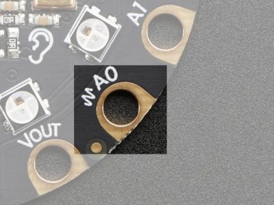
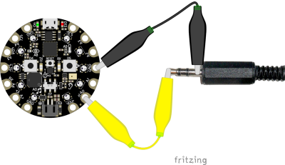
Alligator/Croc Clip Pads:
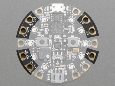
To make it super-easy to connect to the microcontroller, cpx has 14 connection pads. You can solder to them, use alligator/croc clips, sew with conductive thread, even use small m3 metal screws!
Set Up Arduino IDE
The Arduino Integrated Development Environment (IDE) is a cross-platform application (for Windows, macOS, Linux) that is written in functions from C and C++.[3] It is used to write and upload programs to Arduino compatible boards, but also, with the help of third-party cores, other vendor development boards including circuit playground express.
Download and install Arduino IDE:
https://www.arduino.cc/en/software
And follow the step here:
https://learn.adafruit.com/adafruit-circuit-playground-express/set-up-arduino-ide
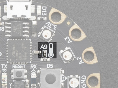
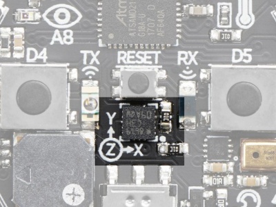
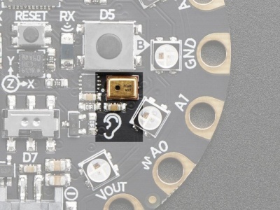
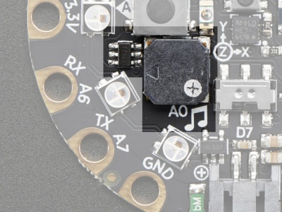
CPX onboard sensors & Pinouts
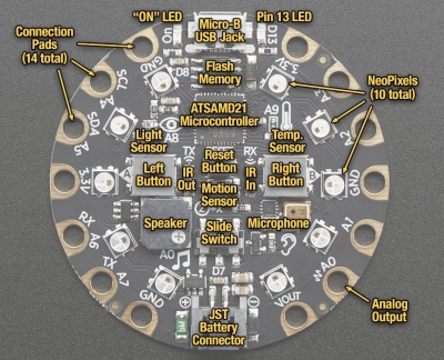
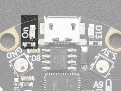
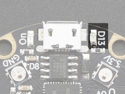
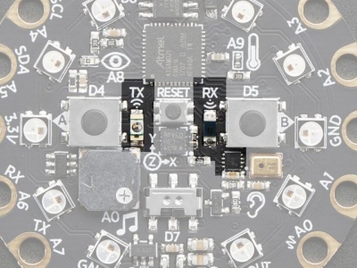
1. Green LED lets you know that the CPX is powered on.------ 2. Red LED on Digital pin#13
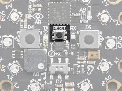
3. This small button is for Resetting the board. ------------------ 4. Button A and B on Digital pin #4 and #5
5. slide switch on Digital pin #7 - - - - - - - - - - - - - - - - - - - - - - 6. 7 Capacitive Touch pads from A1-A7
