Difference between revisions of "Getting Started with Arduino & Lights"
| Line 511: | Line 511: | ||
These are lights that use '''mains electricity voltages (220v)'''. | These are lights that use '''mains electricity voltages (220v)'''. | ||
| − | <div style="color:red;"> | + | <div style="color:red; font-family:monospace;font-size:12pt;"> |
Warning!<br> | Warning!<br> | ||
| − | When working with mains we must be really careful as we are out of the safe area of the low voltages. | + | When working with mains we must be really careful as we are out of the safe area of the low voltages. When you are making projects that are connected to mains voltage, you need to know what you are doing, otherwise you may shock yourself.<br> |
| + | If you’re not sure what you are doing, ask first! | ||
</div> | </div> | ||
Revision as of 15:08, 11 May 2023
Introduction
Are planning to add light to your work?
Do you want the light source in your installation to be controlled by sensor data?
Are you curious about the possibilities of programming lights with Arduino?
During this station skill, you will be introduced to some standard methods of programming lights with Arduino.
Arduino is a microcontroller that makes it easy for us to work with different kinds of hardware like lights, motors and a wide array of sensors. During this station skill, we will use it to work with lights.
We will do this during three sessions, each one focused on working with different kinds of lights: LEDs, LED strips and light bulbs.
Station Skill schedule
Week: 16
Date Fri 21 Apr 2023
Time 09:00-12:00
Arduino & LEDs
Week: 17
Date Fri 28 Apr 2023
Time 09:00-12:00
Arduino & LED strips
Week: 19
Date Sat 13 May 2023
Time 09:00-12:00
Arduino & Relays
Session 1
What can you do with it?
Examples
- Soliloquy, Tromarama, 2018
- wave is my nature, vtol, 2015
- Game of me, Xuanning Chen
- Healer, Pamela Ronsenkranz
- Alain Le Boucher
- Collection of light, Humans since 1982, 2011
- Tatsuo Miyajima
Life (le corps sans organes) - https://tatsuomiyajima.com/work-projects/life-le-corps-sans-organes-no-17-2013-no-10-2014/
- Eigengrau, Zalan Szakacs
Arduino and LEDs
The LED
What is an LED?
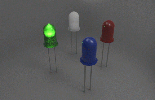
LED is short for light emitting diode, is a semiconductor device that emits light when an electric current is passed through it. Light is produced when the particles that carry the current (electrons and holes) combine together within the semiconductor material.
LEDs come in different colors. Different semiconductor materials with different bandgaps (separation of the bands containing electrons and holes) produce different colors of light.
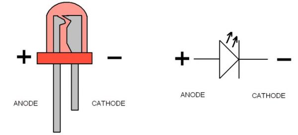
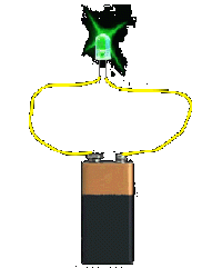
In an LED, energy flows in one direction, generating the luminous effect at the top, where the semiconductor is.
LEDs have two legs, corresponding to the positive and negative side, also known as Anode and Cathode. These can be distinguished because the positive leg, the Anode, is longer than the other one. If we connect these two poles to a battery, the LED will turn on.
Arduino: how does it work
Arduino is a microcontroller, a type of device, like a small computer, designed to execute simple tasks. Arduino is used by a wide for building digital devices and interactive objects that can sense and control the physical world.
You can check other examples of what Arduino can do.
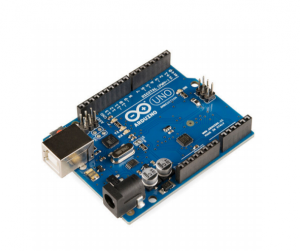
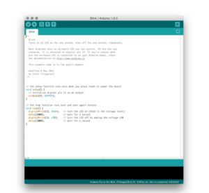
Arduino is composed of two major parts: the Arduino board, which is the piece of hardware you work on when you build your objects; and the Arduino IDE, the piece of software you run on your computer. You use the IDE to create a sketch (a little computer program) that you upload to the Arduino board. The sketch tells the board what to do.
The board
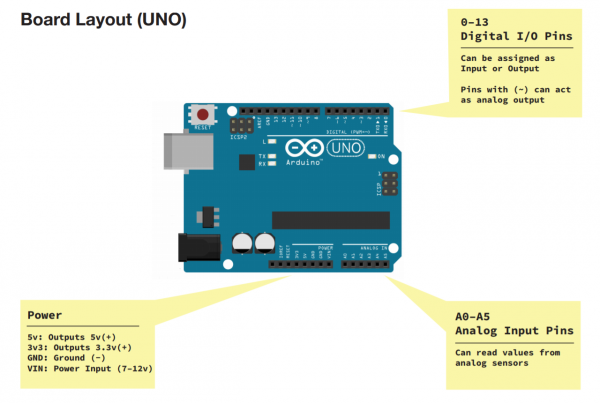
The Arduino board is based on a simple input/output (I/O) logic. On the board you can see a series a pins, which are the places where you connect your external components (like LEDS, sensors and so on) through wires.
The Arduino has different kinds of pins, each of which is labeled on the board and used for different functions.
Analog Input Pins ( we have six of them in the Uno): The area of pins under the ‘Analog In’ label (A0 through A5 on the UNO) are Analog In pins. These pins can read the signal from an analog sensor (like a temperature sensor) and convert it into a digital value that we can read.
Digital Input Pins (seven on the Uno): Across from the analog pins are the digital pins (0 through 13 on the UNO). These pins can be used for both digital input (like telling if a button is pushed) and digital output (like powering an LED).
Connecting the LED to Arduino
Now we are going to connect Arduino to an LED. You will need:
- Arduino board
- a breadboard
- a 220 ohm resistor
- an LED
- jumper wires
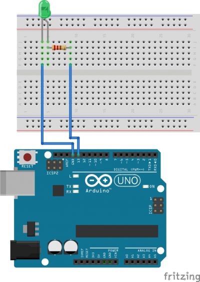
Connect the Pins following the scheme:
- Anode(+) of the LED (the longer leg) to Digital pin 13;
- Cathode(-) of the LED (the shorter leg) to Ground(GND);
You can connect this directly to the Ground Pin or you can connect it to any point the negative rail of the breadboard. This one that needs to be connected to the Ground pin. This last option is preferable in case you want to connect other LEDS or components that also need to be connected to the Ground pin.
Programming the LED
Now we are going to program the board to control the LED.To program your board you can use Arduino's own software that allows use to write code and upload it on the board.
+ Open the Arduino software
You can open the Arduino IDE software on the computer. This is already installed in WH.02.108 and most of the computers at the Interaction Station. If you want you can also use it on your laptop, you can install it thought
this link.
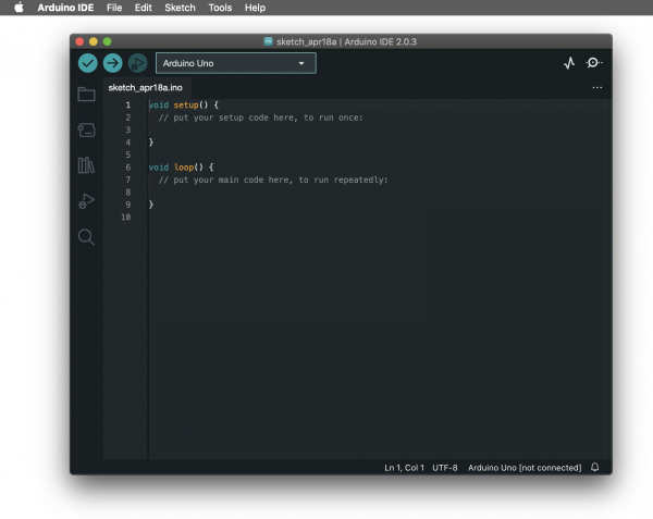
It should look like this:
+ Connect the board
You can now connect the board to the computer: this will enable us to upload the sketch as well as to power the board.
If the software found your board your will see it on the bottom right corner. If not, it will show [not connected].
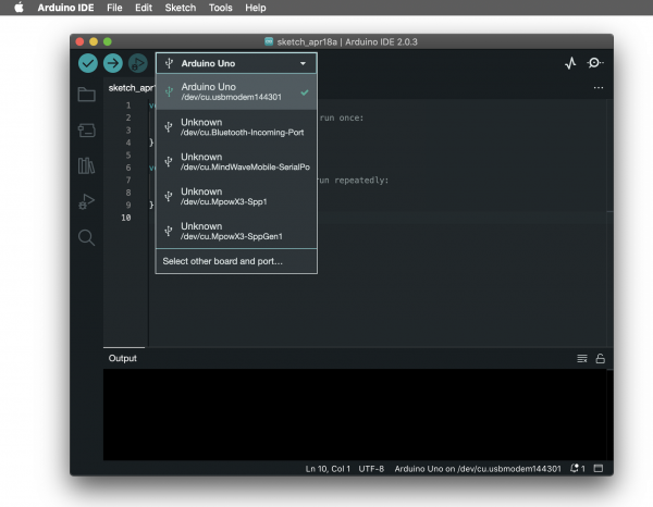
To make select the board and the port you can go to Tools>Board and select your Arduino model, in our case is the Arduino Uno. To check if the right port is selected you can go to Tools>Port and select it. Often the software recognises it already and puts the board name between () after the port name.
In the new version of Arduino you can see board and port directly on your sketch window.
Turn on the LED
void setup() {
  // put your setup code here, to run once:
  pinMode(13, OUTPUT);
  digitalWrite(13, HIGH); // turn LED on (output 5V)
}

void loop() {
  // put your main code here, to run repeatedly:

}
Blinking LED
void setup() {
  // put your setup code here, to run once:
  pinMode(13, OUTPUT);
}

void loop() {
  // put your main code here, to run repeatedly:
    digitalWrite(13, HIGH); // turn LED on (output 5V);
    delay(500);
    digitalWrite(13, LOW); // turn LED on (output 5V);
    delay(500);
}
!!!!Note:
The delay() function pauses the program for an amount of time expressed in milliseconds.
For reference, 1000 milliseconds = 1 second.
Fading LED
int led = 9;         // the PWM pin the LED is attached to
int brightness = 0;  // how bright the LED is
int fadeAmount = 5;  // how many points to fade the LED by

void setup() {
  // put your setup code here, to run once:
  // declare pin 13 to be an output:
  pinMode(led, OUTPUT);
}

void loop() {
  // put your main code here, to run repeatedly:
  // set the brightness of pin 9:
  analogWrite(led, brightness);

  // change the brightness for next time through the loop:
  brightness = brightness + fadeAmount;

  // reverse the direction of the fading at the ends of the fade:
  if (brightness <= 0 || brightness >= 255) {
    fadeAmount = -fadeAmount;
  }
  // wait for 30 milliseconds to see the dimming effect
  delay(30);
}
!!!!Note:
AnalogWrite() uses pulse width modulation (PWM), turning a digital pin on and off very quickly with different ratios between on and off, to create a fading effect. The fading effect is possible to achieve only when using the PWM (Pulse with modulation) Pins. On most Arduino, the PWM pins are identified with a "~" sign. For this reason we moved the LED on Pin 9.
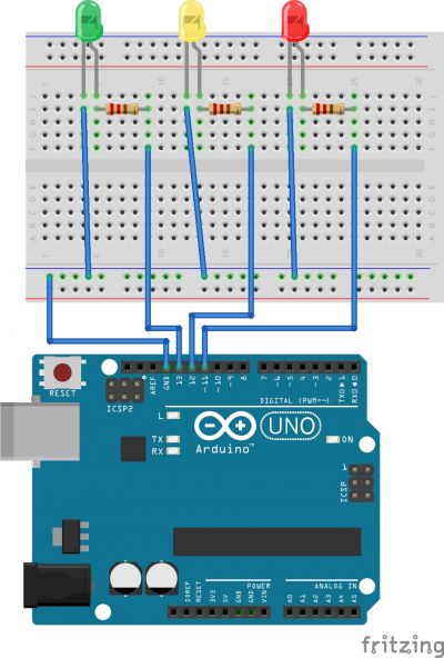
LEDs traffic light
What is you want to connect more than one LED?
int greenLed = 13;
int yellowLed = 12;
int redLed = 11;

void setup() {
  // put your setup code here, to run once:
  pinMode(greenLed, OUTPUT);
  pinMode(yellowLed, OUTPUT);
  pinMode(redLed, OUTPUT);
}

void loop() {

  // put your main code here, to run repeatedly:
    //turn green light on for 3 seconds
    digitalWrite(greenLed, HIGH);
    delay(3000);
    //turn off green light and turn yellow light on for half a second
    digitalWrite(greenLed, LOW); // turn LED on (output 5V);
    digitalWrite(yellowLed, HIGH);
    delay(500);
    //turn off yellow light and turn on red light for 3 seconds
    digitalWrite(yellowLed, LOW); // turn LED on (output 5V);
    digitalWrite(redLed, HIGH);
    delay(3000);
    digitalWrite(redLed, LOW);

}
LED Morse code
Light can also be used to brighten an area or an object but can also be used to send messages. We will try to make our LED talk with the help of an old times favourite: Morse code.
Here is the reference:
Morse code reference

Letters
A .-
B -...
C -.-.
D -..
E .
F ..-.
G --.
H ....
I ..
J .---
K -.-
L .-..
M --
N -.
O ---
P .--.
Q --.-
R .-.
S ...
T -
U ..-
V ...-
W .--
X -..-
Y -.--
Z --..
Numbers
0 -----
1 .----
2 ..---
3 ...--
4 ....-
5 .....
6 -....
7 --...
8 ---..
9 ----.
Punctuation
Period           (.) .-.-.-
Comma            (,) --..--
Question Mark    (?) ..--..
Apostrophe.      (') .----.
Exclamation Mark (!) -.-.--
Prosigns
Starting signal      -.-.-
End of work          ...-.-
New message follows  .-.-.
Since Morse Code is just a combination of dots(.) and dashes (-) we can convert this graphical elements into time units.
dot(.) = 1 unit = 1 second
dash(-) = 3 units = 3 seconds
The space between parts of a letter in 1 unit = 1 second
The space between letters in 3 units = 3 second
The space between words is 7 units = 7 seconds
Resources/More
- About electricity
- About physical computing
- Arduino's official website
- What is a resistor?
- Calculate resistors value on your LED circuit (Series and parallel)
- Arduino functions reference page
- More about making circuits with LEDs: Series and Parallel, calculating resistance and so on
- Getting rid of the delay() and how to use millis() function
Session 2
Arduino and LED strips
LED strips
![]()
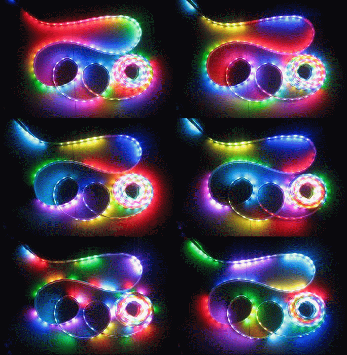
An LED strip consist of many individual LED emitters mounted on a narrow, flexible circuitboard.
Many of the LED strips you can find on the market are commercialised by Adafruit and they are called Neopixels. Each strip (but not only strips, as Neopixels can come in different formats too) is made of separate LEDS called Pixels (one LED = one Pixel).
Every LED that makes a strip (or a Pixel), is actually made of 3 different separate diodes within the same cell, and each of these diodes emits its designated color - red, green, or blue. By programming the intensity of each diode you can obtain different colors.
Luckily for us, most of these strips are compatible with microcontrollers like Arduino, allowing us to program their color, intensity, create animation but not only. You can use those to prototype objects and installations in combination with other components (sensors, motors and so on).
Types of strips
When you are looking for LED strips you’re likely to come across a huge variety of different types. One of the most important distinctions we can do is between digitally addressable strips and not addressable ones.
- Addressable strips
These are the ones that you can program: you can determine pixel by pixel which color, brightness or sequence you want to apply to those. These types usually have 3 pins of more: +,-, signal pin(s).
- Not addressable strips
These types usually come already in a color (usually white, blue, green and so on) that cannot be changed. Unlike the addressable ones you will not be able to specify different settings for each pixel. Your strip will act as a whole.
These strips usually have only two pins: + and - .
If you are about to buy LED strips and you feel overwhelmed by the variety of models, letters and configurations, you should have a look at this
guide first: https://thesmartcave.com/led-strips-guide/.
Powering the LED strips
Another challenge you might encounter while working with LED strips is to understand which is the correct power supply. You can usually determine this by looking at the product data sheet. The requirements of Voltage and current are usually listed there and they vary accordingly to the product.
During this class we will use the Adafruit Neopixel SK6812 made of 30 pixels. This type, as many of the Adafruit models, has an operating voltage of 5V making it perfect to use with an Arduino (as Arduino can provide a max of 5v if not paired with an external power supply).
Calculating the current draw
What is important though to understand is that the intensity of the light of our pixel is not only determined by the voltage but mostly by the current (measured in Ampere = AMPS).
The current (amps) will determine the brightness of your pixel and this depends of course on what you are trying to achieve.
Each individual NeoPixel draws up to 60 milliamps at maximum brightness white (red + green + blue).
In actual use though, it’s rare for all pixels to be turned on that way. When mixing colors and displaying animations, the current draw will be much less. It’s impossible to estimate a single number for all circumstances, but we’ve been using 1/3 this (20 mA per pixel) as a gross rule of thumb with no ill effects. But if you know for a fact that you need every pixel on at maximum brightness, use the full 60 mA figure.
To estimate power supply needs, multiply the number of pixels by 20, then divide the result by 1,000 for the “rule of thumb” power supply rating in Amps. Or use 60 (instead of 20) if you want to guarantee an absolute margin of safety for all situations. For example:
Number of pixels x 20 mA % 1,000 = Amps needed for generic use
Number of pixels x 60 mA % 1,000 = Amps needed for maximum pixel brightness
What if I have a power supply that provides a higher amperage than the maximum I just calculated?
The LED strip will only draw as much current (Amps) as it needs. It will not manage the LED strip.
On the other hand, if you provide a higher voltage than the required one you risk to permanently damage your strip .-..
More amps = good
More volts = really bad
In our case, since we are using a strip made of 30 pixels is going be:
30 NeoPixels × 20 mA ÷ 1,000 = 0.6 Amps needed for generic use
30 NeoPixels × 60 mA ÷ 1,000 = 1.8 Amps Amps needed for maximum pixel brightness
During this class we are going to stick to a generic brightness. We are going to hook up the strip with Arduino using the Arduino 5V pin that provides a maximum of 0.8 amps. Good enough for our strip. If you want to use higher amperage you will need to use an external power supply in combination with your board.
Connecting the LED strip to Arduino
To hook up the strip with Arduino we will use the following scheme:
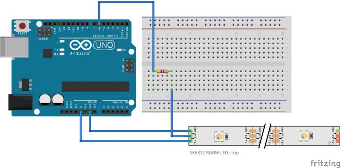
You will need:
- Arduino Uno
- Adafruit Neopixel SK6812 (30 Neopixel)
- a 470 ohms resistor
- a breadboard
- jumper wires
If next time you want to use an external power supply (to provide more amps for instance), you can follow this scheme:
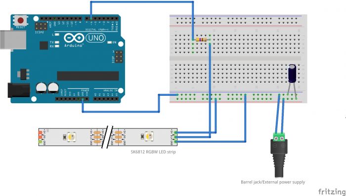
You will need to add:
- external power supply with the desired V & Amps
- a 1000uF capacitor
Programming the LED strip
Installing libraries
In order to program the strip with Arduino we will need to install a library first. A programming library is a collection of prewritten code that programmers can use to optimise tasks. In simple words: code and functions that someone else already wrote (thanks!) to make our life easier.
Some libraries come as a default when you install Arduino. In our case we will need to install it.
To do so you can go to:
Sketch > Import Library
or on the latest Arduino version:
Sketch > Include Library > Manage libraries
At this point you can look for the Adafruit Neopixel library and install it.
Once the library is installed you can go to:
File > Examples > Adafruit Neopixel > Simple
Loop through the pixels
This will open an example code that turn on each pixel one by one.
To do this we will use a for loop.
// NeoPixel Ring simple sketch (c) 2013 Shae Erisson
// Released under the GPLv3 license to match the rest of the
// Adafruit NeoPixel library

#include <Adafruit_NeoPixel.h>
#ifdef __AVR__
 #include <avr/power.h> // Required for 16 MHz Adafruit Trinket
#endif

// Which pin on the Arduino is connected to the NeoPixels?
#define PIN        6 // On Trinket or Gemma, suggest changing this to 1

// How many NeoPixels are attached to the Arduino?
#define NUMPIXELS 16 // Popular NeoPixel ring size

// When setting up the NeoPixel library, we tell it how many pixels,
// and which pin to use to send signals. Note that for older NeoPixel
// strips you might need to change the third parameter -- see the
// strandtest example for more information on possible values.
Adafruit_NeoPixel pixels(NUMPIXELS, PIN, NEO_GRB + NEO_KHZ800);

#define DELAYVAL 500 // Time (in milliseconds) to pause between pixels

void setup() {
  // These lines are specifically to support the Adafruit Trinket 5V 16 MHz.
  // Any other board, you can remove this part (but no harm leaving it):
#if defined(__AVR_ATtiny85__) && (F_CPU == 16000000)
  clock_prescale_set(clock_div_1);
#endif
  // END of Trinket-specific code.

  pixels.begin(); // INITIALIZE NeoPixel strip object (REQUIRED)
}

void loop() {
  pixels.clear(); // Set all pixel colors to 'off'

  // The first NeoPixel in a strand is #0, second is 1, all the way up
  // to the count of pixels minus one.
  for(int i=0; i<NUMPIXELS; i++) { // For each pixel...

    // pixels.Color() takes RGB values, from 0,0,0 up to 255,255,255
    // Here we're using a moderately bright green color:
    pixels.setPixelColor(i, pixels.Color(0, 150, 0));

    pixels.show();   // Send the updated pixel colors to the hardware.

    delay(DELAYVAL); // Pause before next pass through loop
  }
}
Add a potentiometer to control the brightness
We know you can control the brightness of the pixel in the same way you determine the color. With this method though, it is not so smooth to reach the desired color and brightness as it requires some calculations.
Luckily, we can use the function pixels.setBrightness(brightness) to set a general brightness value for the pixels;
The brightness value goes from 0 to 255.
Now, let's add a potentiometer. In this case we will use a 10k ohm potentiometer.
You can use the following scheme:
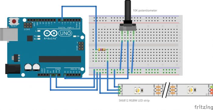
// NeoPixel Ring simple sketch (c) 2013 Shae Erisson
// Released under the GPLv3 license to match the rest of the
// Adafruit NeoPixel library

#include <Adafruit_NeoPixel.h>
#ifdef __AVR__
 #include <avr/power.h> // Required for 16 MHz Adafruit Trinket
#endif

// Which pin on the Arduino is connected to the NeoPixels?
#define PIN        6 // On Trinket or Gemma, suggest changing this to 1

// How many NeoPixels are attached to the Arduino?
#define NUMPIXELS 30 // Popular NeoPixel ring size

// When setting up the NeoPixel library, we tell it how many pixels,
// and which pin to use to send signals. Note that for older NeoPixel
// strips you might need to change the third parameter -- see the
// strandtest example for more information on possible values.
Adafruit_NeoPixel pixels(NUMPIXELS, PIN, NEO_GRB + NEO_KHZ800);

#define DELAYVAL 500 // Time (in milliseconds) to pause between pixels

void setup() {
  Serial.begin(9600);
  // These lines are specifically to support the Adafruit Trinket 5V 16 MHz.
  // Any other board, you can remove this part (but no harm leaving it):
#if defined(__AVR_ATtiny85__) && (F_CPU == 16000000)
  clock_prescale_set(clock_div_1);
#endif
  // END of Trinket-specific code.

  pixels.begin(); // INITIALIZE NeoPixel strip object (REQUIRED)
}

void loop() {

//Serial.print("hello");
  int potValue = analogRead(A0);
  int brightness = map (potValue, 0,1023,0,255);
  // print out the value you read:
  Serial.println(potValue);
  Serial.println(brightness);
  //delay(1);  // delay in between reads for stability

  //pixels.clear(); // Set all pixel colors to 'off'
  pixels.setBrightness(brightness);

    for(int i=0; i<NUMPIXELS; i++) { // For each pixel...
    // pixels.Color() takes RGB values, from 0,0,0 up to 255,255,255
    // Here we're using a moderately bright green color:
    pixels.setPixelColor(i, pixels.Color(0, 255, 0));
    pixels.show();   // Send the updated pixel colors to  the hardware.
    //delay(DELAYVAL); // Pause before next pass through loop
  }
}
Resources/More
- About LED lights colors
- An in-depth guide on working with Neopixels
- Another guide, especially useful if you want to connect more strips together in a big size project
- Adadruit Neopixel library reference
- Arduino for loop reference
- Potentiometers for dummies
Session 3
High power lights
The lightbulb
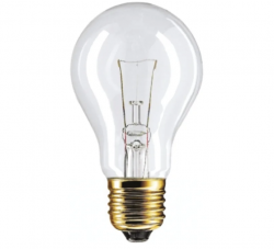
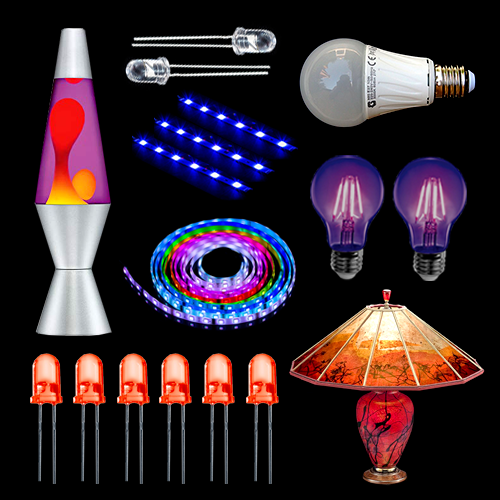
In practice, the lightbulb is a very thin filament of hard-to-melt metal – tungsten, usually – placed in a glass bulb filled with inert gases so that the filament doesn’t oxidise and disintegrate. The flow of electricity causes the wire to glow and a portion of that energy is turned into light. Unlike in LED lights, in a lightbulb most of the energy turns into heat.
Gas discharge lamps
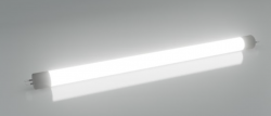
Discharge lamps generate electromagnetic radiation (light) by means of an electric current passing through a gas or metal vapour instead of a metal filament like in the case of a light bulb.
A discharge lamp consists essentially of a tube of glass, quartz or other suitable material, containing a gas and, in most cases, a metal vapour. The passage of an electric current through this gas/vapour produces light or ultraviolet radiation.
Types of discharge lamps are Neon lights (using neon gas as the name suggests) or UV lights emitting UV radiations.
These are lights that use mains electricity voltages (220v).
Warning!
When working with mains we must be really careful as we are out of the safe area of the low voltages. When you are making projects that are connected to mains voltage, you need to know what you are doing, otherwise you may shock yourself.
If you’re not sure what you are doing, ask first!
Arduino and Relays: how to control light bulbs (and not only)
Until now we have been working with lights that operate on the same voltages of the Arduino board (low voltages like 5 or 12 for LEDs and LED strips).
As we saw these light sources operate with mains electricity voltages (220 volts). An Arduino though works with 5 volt: this will not be enough to power light bulbs and similar. As well, connecting an Arduino directly to a high voltage circuit will burn your board :( .
For this reason we will need to use something that can help us to make the Arduino board able to communicate to mains. To do so we will use a Relay.
The Relay
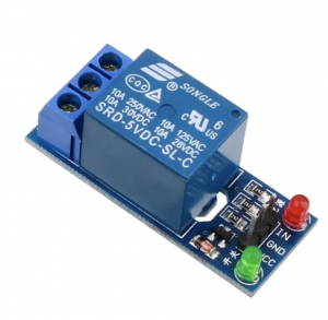
A Relay is an electrically operated switch that can be used to turn on and off a circuit by a low lower signal.
This switch can determine whether letting the current go through or not, and can be controlled with low voltages, like the 5V provided by the Arduino pins.
How does it work?
Look at this video.
In simple terms a Relay is made of two separate circuits, a LOAD CIRCUIT connected to high voltages (mains power and so our light) and a CONTROL CIRCUIT powered by our Arduino board and operating at 5v. When the control switch is turned on, current flows through a coil generating a magnetic field that opens or closes the load circuit.
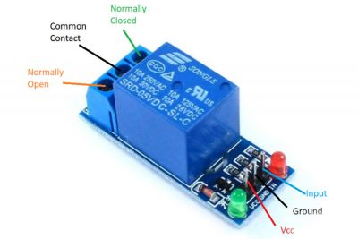
Relay pins:
Control Circuit
IN (or S): Signal pin
GND (or -): Ground
VCC (or +): Power input
Load Circuit
COM:common pin
NC (Normally Closed): the normally closed configuration is used when you want the relay to be closed by default, meaning the current is flowing unless you send a signal from the Arduino to the relay module to open the circuit and stop the current.
NO (Normally Open): the normally open configuration works the other way around: the relay is always open, so the circuit is broken unless you send a signal from the Arduino to close the circuit. If you just want to light up a lamp occasionally, it is better to use a normally-open circuit configuration.
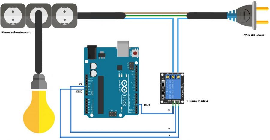
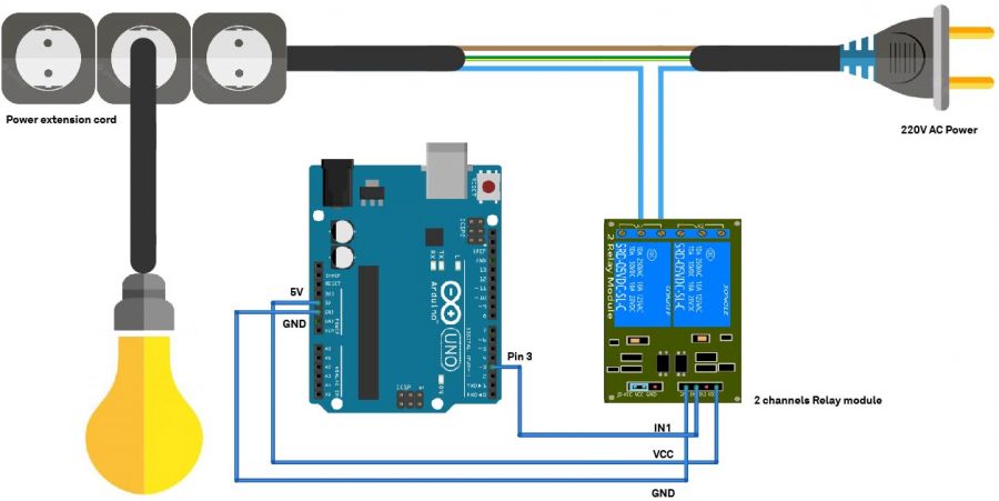
Connecting the Relay and the light bulb to Arduino
The Relays we have at the station are of two types: one channel or two channels. The two channels is able to control two different outputs.
The wiring is as it follows:
One channel
Programming the relay
// constants won't change
const int RELAY_PIN = 3;  // the Arduino pin, which connects to the IN pin of relay


// the setup function runs once when you press reset or power the board
void setup() {
  //Start serial communication
  Serial.begin(9600);
  // initialize digital pin as an output.
  pinMode(RELAY_PIN, OUTPUT);
}

// the loop function runs over and over again forever
void loop() {
  //change the state of the relay every 2 seconds
  digitalWrite(RELAY_PIN, HIGH);
  Serial.println("Relay off");
  delay(2000);
  digitalWrite(RELAY_PIN, LOW);
  Serial.println("Relay on");
  delay(2000);
}
Add a light sensor
The LDR
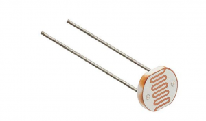
An LDR(=Light dependent resistor) is a sensor (or more properly a resistor) that is able to detect light levels.
How does it work?
Basically a LDR is a resistor whose resistance value is not fixed, instead its resistance decreases as the light intensity increases. This happens because the semi-conductive material os the resistor contains photosensitive cadmium sulphide.
The LDR gives out an analog voltage when connected to VCC (5V), which varies in magnitude in direct proportion to the input light intensity on it. That is, the greater the intensity of light, the greater the corresponding voltage from the LDR will be. Since the LDR gives out an analog voltage, it is connected to the analog input pin on the Arduino. The Arduino, with its built-in ADC (analog-to-digital converter), then converts the analog voltage (from 0-5V) into a digital value in the range of (0-1023).
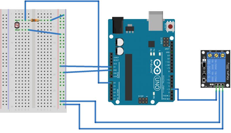
Connect the LDR to Arduino
Program the LDR
// constants won't change
const int RELAY_PIN = 3;  // the Arduino pin, which connects to the IN pin of relay
const int LDR_PIN = A0; // the Arduino pin (analog) connected to the LDR

// the setup function runs once when you press reset or power the board
void setup() {
  //Start serial communciation
  Serial.begin(9600);
  // initialize digital pin as an output.
  pinMode(RELAY_PIN, OUTPUT);
  // initialize analog pin as an input.
  pinMode(LDR_PIN, INPUT);
}

// the loop function runs over and over again forever
void loop() {
  //read LDR sensor data
  int LDR_state = analogRead(LDR_PIN);
  //print it on serial monitor
  Serial.println(LDR_state);
  //turn light off is the LDR state value is more than 300 or turn it off if is less
  if (LDR_state > 300){
    digitalWrite(RELAY_PIN, HIGH);
    Serial.println("Relay off");
  }
  else{
    digitalWrite(RELAY_PIN, LOW);
    Serial.println("Relay on");
  }

}
