Difference between revisions of "RPi/datalogger"
m |
|||
| Line 33: | Line 33: | ||
The OLED display has to be connector to I2C-1 | The OLED display has to be connector to I2C-1 | ||
| − | The datalogger needs to be told what sensor is connected. To do this there is a file in the BOOT partition of the Raspberry PI SD card. This file is called <code>sensors.txt</code>. In this file uncomment the sensor connected and comment the rest by placing a # in front of the sensor name. | + | The datalogger needs to be told what sensor is connected. To do this there is a file in the BOOT partition of the Raspberry PI SD card. This file is called <code>sensors.txt</code>. In this file uncomment the sensor connected and comment the rest by placing a # in front of the sensor name.<br> |
=Reading the log file= | =Reading the log file= | ||
Revision as of 19:35, 30 April 2017
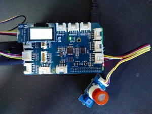
The data logger is a grovepi+ shield with attached:
- a grove sensor
- a grove OLED 128x64 display
- a GPS USB dongle
The PI can be powered by a USB power bank.
Note: When using a Raspberry PI A or B (not B+) the sudden current draw may cause the powerbank to shutdown. Quickly unplugging an plugging back in can help. If not, remove the grove shield, plug in the powerbank and attach the shield. From B+ and up this problem does not occur.
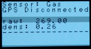
As soon as the datalogger is booted (can take a while) the OLED screen will show something similar as:

It shows the following:
- type of sensor
- GPS status
- sensor data
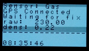
If the GPS is switched on (blue led on the GPS dongle is on) the display will show the following:

The last line will show the actual time in UTC and the GPS status shows either if it is waiting for a GPS fix or (when the blue light on the GPS is blinking) the LAT and LON coordinates of the last received message.
Attaching the sensor
Currently there are 7 sensors possible:
- Sound sensor (connected to A0)
- Moist sensor (connected to A0)
- Temperature & Humidity (connected to D4)
- Gas sensor MQ-9 (connected to A0)
- LDR (non-grove) (connected to A0)
- Air quality sensor (connected to A0)
- UV sensor (connected to A0)
The OLED display has to be connector to I2C-1
The datalogger needs to be told what sensor is connected. To do this there is a file in the BOOT partition of the Raspberry PI SD card. This file is called sensors.txt. In this file uncomment the sensor connected and comment the rest by placing a # in front of the sensor name.
Reading the log file
As soon as the datalogger is turned on and the GPS is connected it will start logging data in the log.csv file in the BOOT partition of the Raspberry PI SD card. It will start logging even if there is no valid GPS fix. So the logger can be used indoors as well. Wheter there is a valid GPS coordinate associated with a log entry can be seen by the Fix field in the log file. If this field contains a 0 the coordinates for this entry are either the last valid coordinates or the coordinates hardcoded if there has not been a fix before.
The log.csv is a standard CSV file with the following columns:
- timestamp (UTC)
- latitude
- longitude
- signal quality
- sensor type
- following column(s) are sensor dependant
Each time the datalogger is started a new header and entries are appended to any existing log file. Hence it is possible for the log.csv file to contain multiple headers. If a clean log file is needed, remove it before starting the datalogger or remove previous entries up to the last occurrence of the header.
Example log entry
timestamp (UTC),latitude,longitude,signal quality,sensor type,density
13:38:54,51.918777,4.486358,0,"Grove gas MQ9 sensor (CO, Coal, Liquified)",0.12
