Difference between revisions of "An Introduction to Wearable Electronics"
| Line 120: | Line 120: | ||
=== Batteries and Power Supply=== | === Batteries and Power Supply=== | ||
| + | [[file:Batteries.jpg]] | ||
| + | |||
=== Breadboards === | === Breadboards === | ||
=== Wire === | === Wire === | ||
Revision as of 06:26, 12 January 2020
Basic Introduction to Electronics
Electricity!
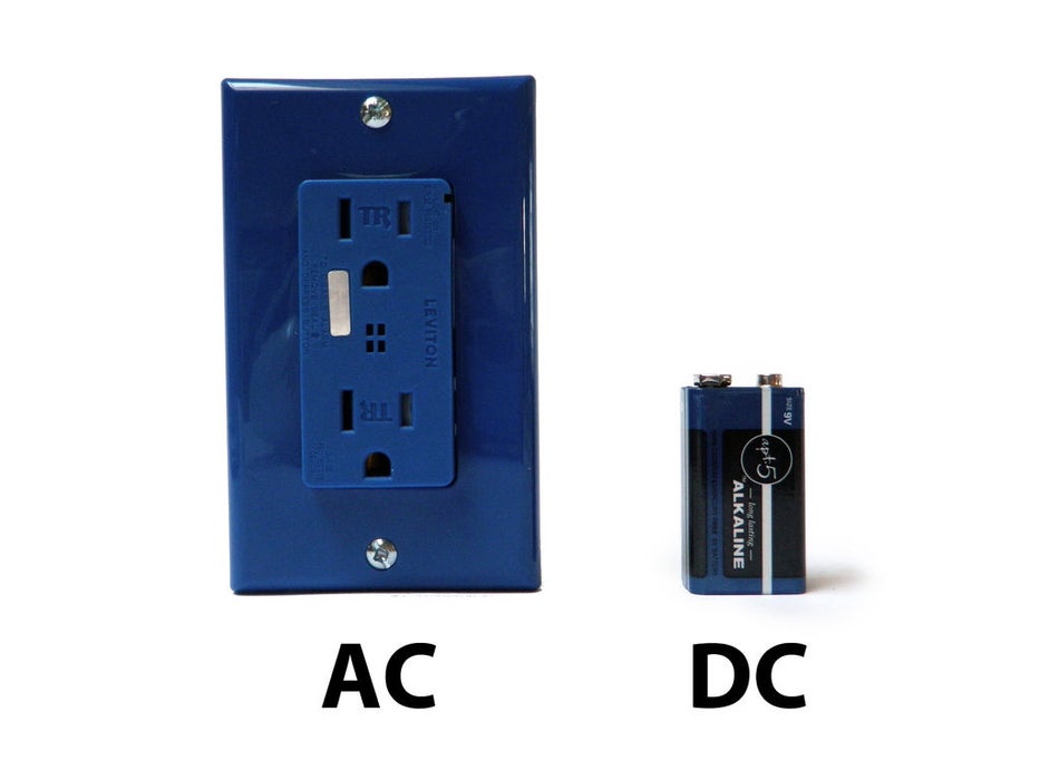
There are two types of electrical signals, those being alternating current (AC), and direct current (DC).
With alternating current, the direction electricity flows throughout the circuit is constantly reversing.
You may even say that it is an alternating direction. The rate of reversal is measured in Hertz, which is the number of reversals per second.
So, when they say that the US power supply is 60 Hz, what they mean is that it is reversing 120 times per second (twice per cycle).
With Direct Current, electricity flows in one direction between power and ground. In this arrangement,
there is always a positive source of voltage and ground (0V) source of voltage. You can test this by reading a battery with a multimeter.
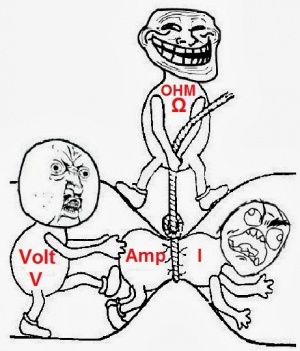
Speaking of voltage, electricity is typically defined as having a voltage and a current rating.
Voltage is obviously rated in Volts and current is rated in Amps. For instance,
a brand new 9V battery would have a voltage of 9V and a current of around 500mA (500 milliamps).
Electricity can also be defined in terms of resistance and watts. We will talk a little bit about resistance in the next step,
but I am not going to be going over Watts in depth. As you delve deeper into electronics you will encounter components with Watt ratings.
It is important to never exceed the wattage rating of a component, but fortunately, that Wattage of your DC power supply can easily be calculated
by multiplying the voltage and current of your power source.
If you want a better understanding of these different measurements, what they mean, and how they relate,
check out this [informative video] on Ohm's Law.
Circuits
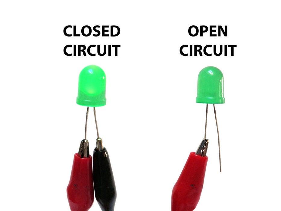
A circuit is a complete and closed path through which electric current can flow. In other words, a closed-circuit would allow the flow of electricity between power and ground. An open circuit would break the flow of electricity between power and ground.
Anything that is part of this closed system and that allows electricity to flow between power and ground is considered to be part of the circuit.
Resistance & short circuits
In the circuit above, the motor that electricity is flowing through is adding resistance to the flow of electricity. Thus, all of the electricity passing through the circuit is being put to use.
In other words, there needs to be something wired between positive and ground that adds resistance to the flow of electricity and uses it up. If a positive voltage is connected directly to the ground and does not the first pass through something that adds resistance, like a motor, this will result in a short circuit. This means that the positive voltage is connected directly to the ground.
Likewise, if electricity passes through a component (or group of components) that does not add enough resistance to the circuit, a short will likewise occur (see Ohm's Law video).
Shorts are bad because they will result in your battery and/or circuit overheating, breaking, catching on fire, and/or exploding.
It is very important to prevent short circuits by making sure that the positive voltage is never wired directly to the ground.
That said, always keep in mind that electricity always follows the path of least resistance to ground. What this means is that if you give positive voltage the choice to pass through a motor to ground, or follow a wire straight to ground, it will follow the wire because the wire provides the least resistance. This also means that by using the wire to bypass the source of resistance straight to the ground, you have created a short circuit. Always make sure that you never accidentally connect positive voltage to the ground while wiring things in parallel.
Also, note that a switch does not add any resistance to a circuit and simply adding a switch between power and ground will create a short circuit.
Series Vs. Parallel
There are two different ways in which you can wire things together called series and parallel.
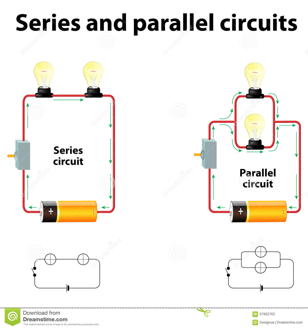
When things are wired in series, things are wired one after another, such that electricity has to pass through one thing, then the next thing, then the next, and so on.
In the left picture, the lightbulbs, switch, and battery are all wired in series because the only path for electricity to flow is from one to the next, and to the next.
When things are wired in parallel, they are wired side by side, such that electricity passes through all of them at the same time, from one common point to another common point
In the next example, the lightbulbs are wired in parallel because the electricity passes through both lightbulbs from one common point to another common point.
If this does not make sense yet, do not worry. When you start to build your own circuits, all of this will start to become clear.
Series and Parallel Circuits have different resistance even with the same components.
In Series Circuits the total resistance Rt=R1+R2
In Parallel Circuits the total resistance will be smaller than Series Circuits: 1/Rt=(1/R1)+(1/R2)
Basic Components
Resistors
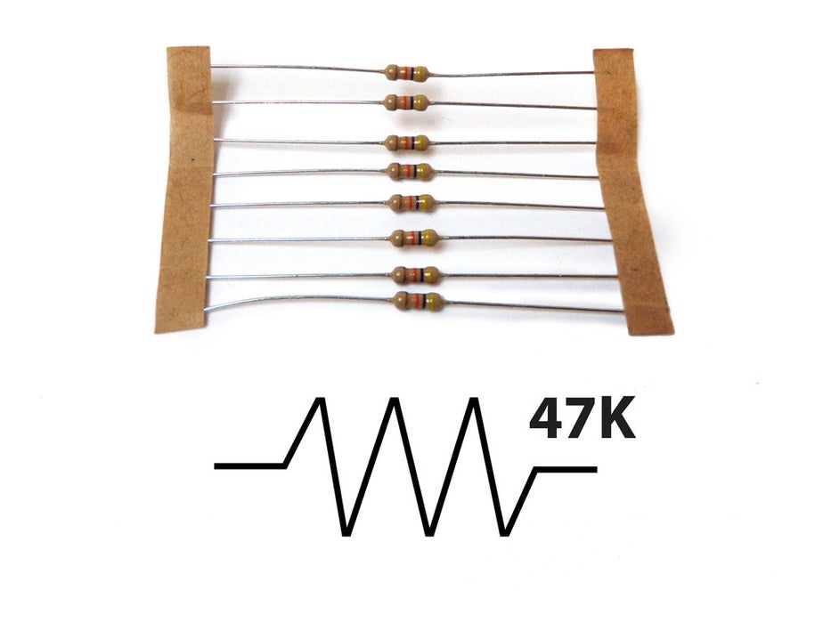
As the name implies, resistors add resistance to the circuit and reduce the flow of electrical current. It is represented in a circuit diagram as a pointy squiggle with a value next to it.
The different markings on the resistor represent different values of resistance. These values are measured in ohms.
Resistors also come with different wattage ratings. For most low-voltage DC circuits, 1/4 watt resistors should be suitable.
You read the values from left to right towards the (typically) gold band. The first two colors represent the resistor value, the third represents the multiplier, and the fourth (the gold band) represents the tolerance or precision of the component. You can tell the value of each color by looking at a resistor color value chart.
Or... to make your life easier, you could simply look up the values using a [graphical resistance calculator].
Anyhow... a resistor with the markings brown, black, orange, gold will translate as follows:
1 (brown) 0 (black) x 1,000 = 10,000 with a tolerance of +/- 5%
Any resistor of over 1000 ohms is typically shorted using the letter K. For instance, 1,000 would be 1K; 3,900, would translate to 3.9K; and 470,000 ohms would become 470K.
Values of ohms over a million are represented using the letter M. In this case, 1,000,000 ohms would become 1M.
