How it's made
Physical computing
example of projects
Basic electronics and circuits
Basic electronic components and sensors
Arduino introduction
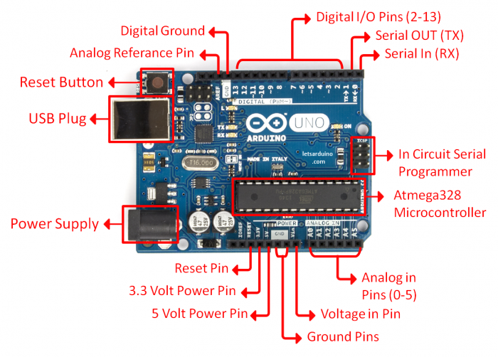
Arduino is an open-source physical computing platform based on a simple input/output (I/O) board and a development environment that implements the Processing language. Arduino can be used to develop standalone interactive objects
or can be connected to software on your computer.
What Is Physical Computing?
Physical Computing uses electronics to prototype new materials for designers and artists.
Arduino is composed of two major parts: the Arduino board, which is the piece of hardware you work on when you build your objects; and the Arduino IDE, the piece of software you run on your computer. You use the IDE to create
a sketch (a little computer program) that you upload to the Arduino board. The sketch tells the board what to do.
In the meantime, HERE you can find ANYTHING about Arduino, including download the software
NOW,
FIRST
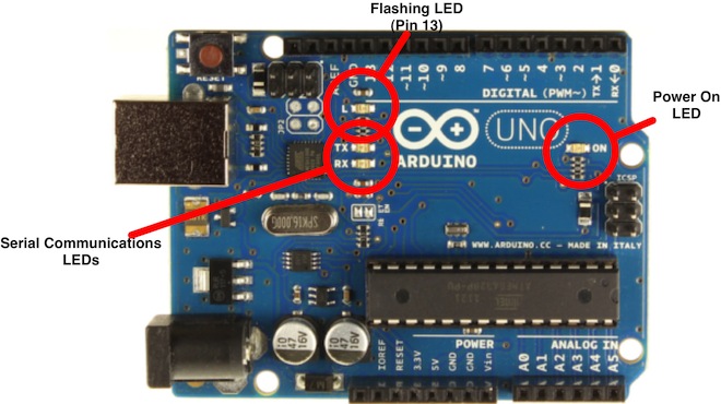
we start by figuring put if our Arduino is all good or it is somehow damaged ...it is a basic test to check and run a simple script at the same time.
Go to File ---> Examples ---> Basics --->Blink
so we have something like this
/*
  Blink
  Turns on an LED on for one second, then off for one second, repeatedly.

  Most Arduinos have an on-board LED you can control. On the Uno and
  Leonardo, it is attached to digital pin 13. If you're unsure what
  pin the on-board LED is connected to on your Arduino model, check
  the documentation at http://www.arduino.cc

  This example code is in the public domain.

  modified 8 May 2014
  by Scott Fitzgerald
 */


// the setup function runs once when you press reset or power the board
void setup() {
  // initialize digital pin 13 as an output.
  pinMode(13, OUTPUT);
}

// the loop function runs over and over again forever
void loop() {
  digitalWrite(13, HIGH);   // turn the LED on (HIGH is the voltage level)
  delay(1000);              // wait for a second
  digitalWrite(13, LOW);    // turn the LED off by making the voltage LOW
  delay(1000);              // wait for a second
}
GOOOD! lets dissect this
- commenting / one line and multiple lines
- setup
- loop
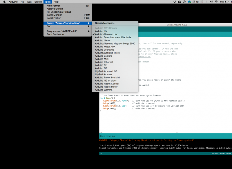
Choose board
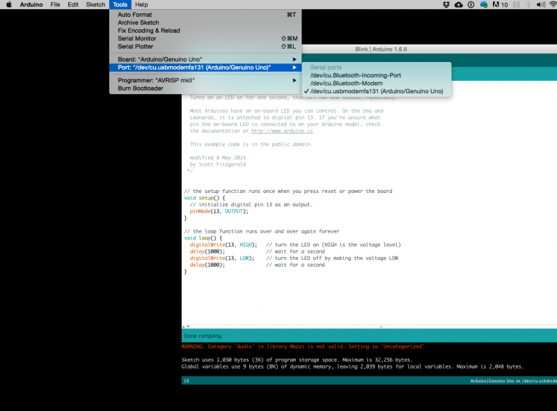
Choose port
Lets compile this
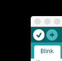
--- Press/ Click upper most left button, looks like a Tick. Observe the messages appearing in the bottom of the Arduino software window ( there must be a sentence Done Compiling
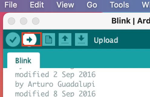
Lets upload this
And we should have a Blinking aka Flashing on board LED
OK, so your Ardiono blinks, that was Hello World!'
Simple circuits and sketches
Now let's try out some simple circuits and Arduino sketches:
microcontrollers
Computer and processor are generic terms for anything that can run a program, basically. A controller or microcontroller usually refers to a simple processor that does only one task, like listening to sensors. In explaining microcontrollers, we’ll distinguish them from computers, which contain more powerful processors that can run an operating system.
besides Arduino, there are also a lot of other microcontrollers available.
for example, we also have many Adafruit circuit playgrounds express and bluefruit at the interaction station.
You can also program them with Arduino IDE.
Check out this link:
Sensors and Actuators
Sensing
we often construct our reality using our sensory experience:
our visual and sound come from our eyes and ears, we can feel the moisture level on our skins, we can feel the gravity and orientation thanks to our inner ear structures.
and now imagine all the sensory input can be converted into digits and feed to a computer, and the computer device can decide what to do(output) with the input data. let's look back to the Shannon-Weaver model of communication.
there is so many already made sensor module for Arduino. Many sensors can detect signals or pick up data beyond human senses. For example ultrasonic sensors.
Imagine we can use these sensor technologies to expand our senses and "reality".
Back to the Sensors: In General, there are two types of sensors: analog and digital.
The analog sensor can detect a range of data. (for example from 0-1020)
The digital sensor can detect either 0 or 1. (or HIGHT /LOW).
for better understanding: the analog sensor is like a dimmer and the digital sensor is like a normal switch.
Here is a list of sensors and examples:
'''Comment sensors:'''
 Don't need additional libraries, normally included in Arduino's example tutorials.

 Potential meters: AnalogReadSerial
 Botton or switch: Button
 Ultrasonic sensor: Ping
 Mic or piezo: knock
               toneMultiple
 Flex & force sensor: toneKeyboard
 LDR (Light Dependent Resistor):
 Calibration
 tonePitchFollower
 Need to install additional libraries.

 Capacitive Sensor-Analog : adafruit-cap1188-breakout
 Or touch-board
 Pulse sensor(heart rate): pulsesensor
 UV sensor:  uv-index-sensor
 Gyroscope/acceleration meter:Gyroscope/acceleration
Actuators with Adafruit Motor Shield
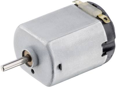
DC motor
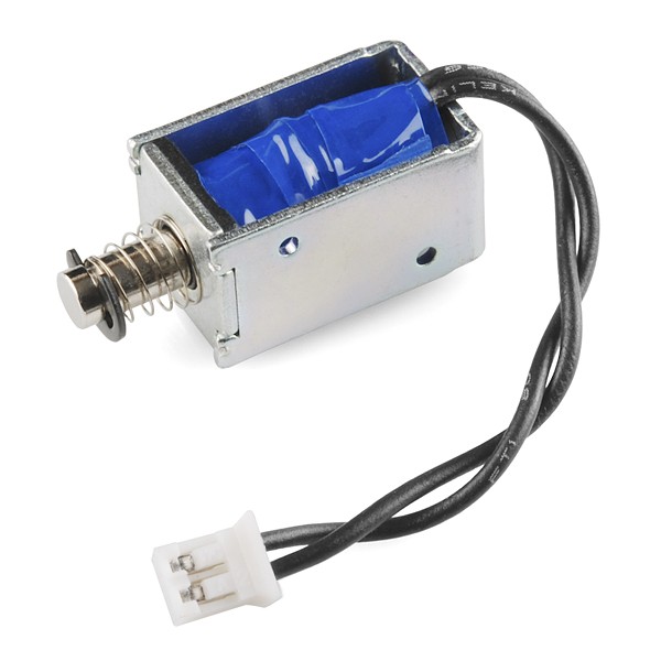
push-pull solenoid
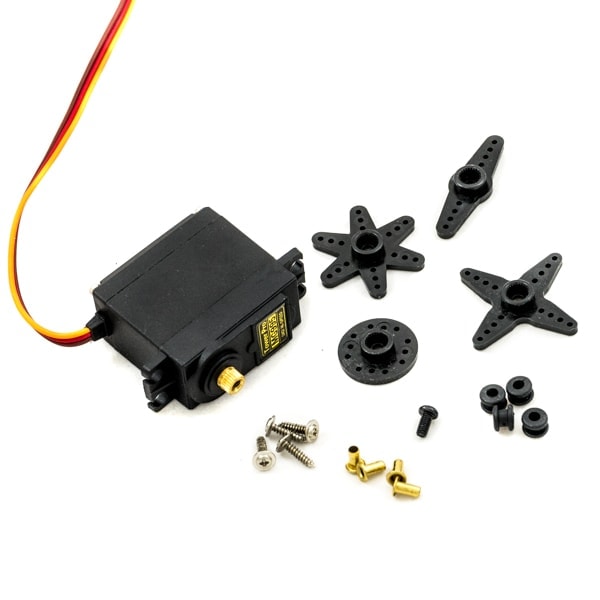
Servo motor
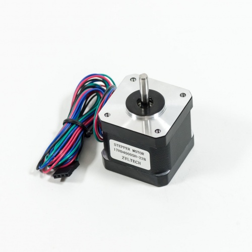
Stepper motor
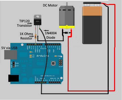
TIP 120 circuit
Transistors are powerful little electronic switches, and when our little NPN transistors aren't powered enough for your project, we have been known to use these beefy TIP120 Darlington transistors. Great for whenever you need to control medium to high-power electronics such as motors, solenoids, or 1W+ LEDs.
 1void setup ()
 2{
 3  pinMode(11, OUTPUT);
 4}
 5
 6void loop ()
 7{
 8  analogWrite(11, 255);
 9  delay(2500);
10  analogWrite(11, 0);
11  delay(2500);
12}
Relay Module
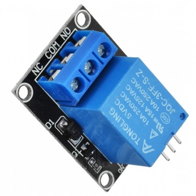
Introducing the Relay Module
A relay is an electrically operated switch. It means that it can be turned on or off, letting the current go through or not.
Controlling a relay with the Arduino is as simple as controlling an output such as an LED.
Notice the writing on the module terminals
COM: common pin
NO (Normally Open): there is no contact between the common pin and the normally open pin. So, when you trigger the relay, it connects to the COM pin, and supply is provided to a load
NC (Normally Closed): there is contact between the common pin and the normally closed pin. There is always a connection between the COM and NC pins, even when the relay is turned off. When you trigger the relay, the circuit is opened and there is no supply provided to a load.
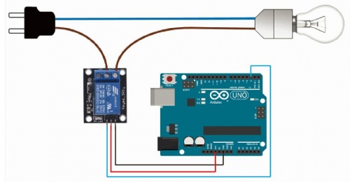
If you want to control a lamp, for example, it is better to use a normally open circuit, because we just want to light up the lamp occasionally.
it is very straightforward as you can see. But always double-check the relay module connections before you plug things together.
GND: goes to ground
VCC: goes to 5V
IN1: controls the relay (it is connected to an Arduino digital pin)
