Getting Started with Arduino & Lights
Introduction
Are planning to add light to your work?
Do you want the light source in your installation to be controlled by sensor data?
Are you curious about the possibilities of programming lights with Arduino?
During this station skill, you will be introduced to some standard methods of programming lights with Arduino.
Arduino is a microcontroller that makes it easy for us to work with different kinds of hardware like lights, motors and a wide array of sensors. During this station skill, we will use it to work with lights.
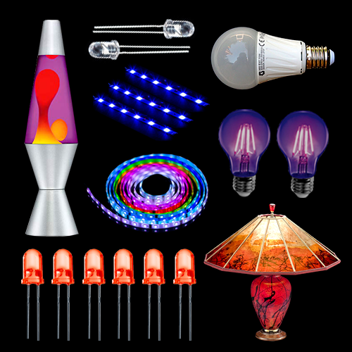
We will do this during three sessions, each one focused on working with different kinds of lights: LEDs, LED strips and light bulbs.
Station Skill schedule
Week: 16
Date Fri 21 Apr 2023
Time 09:00-12:00
Arduino & LEDs
Week: 17
Date Fri 28 Apr 2023
Time 09:00-12:00
Arduino & LED strips
Week: 19
Date Sat 13 May 2023
Time 09:00-12:00
Arduino & Relays
Session 1
What can you do with it?
Examples
- Soliloquy, Tromarama, 2018
- wave is my nature, vtol, 2015
- Game of me, Xuanning Chen
- Healer, Pamela Ronsenkranz
- Alain Le Boucher
- Collection of light, Humans since 1982, 2011
- Tatsuo Miyajima
Life (le corps sans organes) - https://tatsuomiyajima.com/work-projects/life-le-corps-sans-organes-no-17-2013-no-10-2014/
Arduino and LEDs
The LED
What is an LED?
LED is short for light emitting diode, is a semiconductor device that emits light when an electric current is passed through it. Light is produced when the particles that carry the current (electrons and holes) combine together within the semiconductor material.
LEDs come in different colors. Different semiconductor materials with different bandgaps (separation of the bands containing electrons and holes) produce different colors of light.
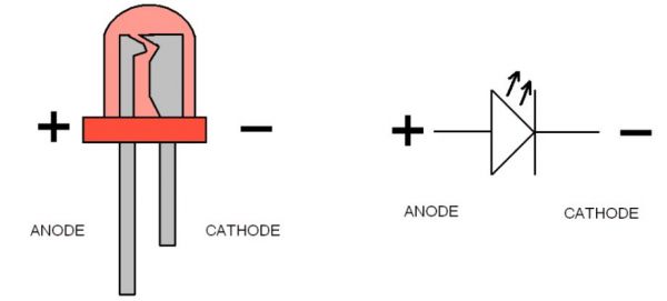
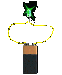
In an LED, energy flows in one direction, generating the luminous effect at the top, where the semiconductor is.
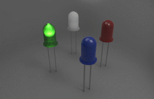
LEDs have two legs, corresponding to the positive and negative side, also known as Anode and Cathode. These can be distinguished because the positive leg, the Anode, is longer than the other one. If we connect these two poles to a battery, the LED will turn on.
Arduino: how does it work
Arduino is a microcontroller, a type of device, like a small computer, designed to execute simple tasks. Arduino is used by a wide for building digital devices and interactive objects that can sense and control the physical world.
You can check other examples of what Arduino can do.
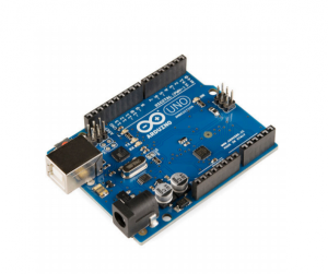
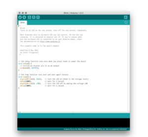
Arduino is composed of two major parts: the Arduino board, which is the piece of hardware you work on when you build your objects; and the Arduino IDE, the piece of software you run on your computer. You use the IDE to create a sketch (a little computer program) that you upload to the Arduino board. The sketch tells the board what to do.
The board
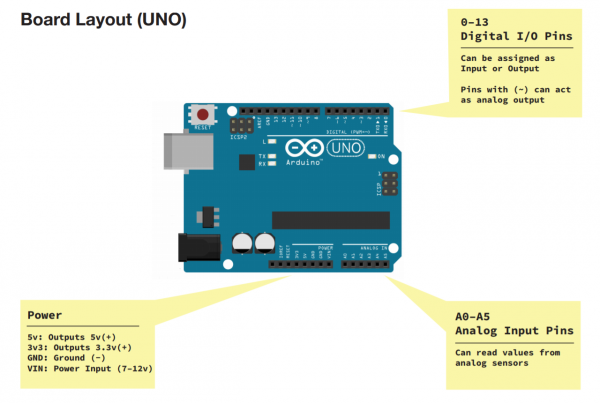
The Arduino board is based on a simple input/output (I/O) logic. On the board you can see a series a pins, which are the places where you connect your external components (like LEDS, sensors and so on) through wires.
The Arduino has different kinds of pins, each of which is labeled on the board and used for different functions.
Analog Input Pins ( we have six of them in the Uno): The area of pins under the ‘Analog In’ label (A0 through A5 on the UNO) are Analog In pins. These pins can read the signal from an analog sensor (like a temperature sensor) and convert it into a digital value that we can read.
Digital Input Pins (seven on the Uno): Across from the analog pins are the digital pins (0 through 13 on the UNO). These pins can be used for both digital input (like telling if a button is pushed) and digital output (like powering an LED).
Connecting the LED to Arduino
Now we are going to connect Arduino to an LED. You will need:
- Arduino board
- a breadboard
- a 220 ohm resistor
- an LED
- jumper wires
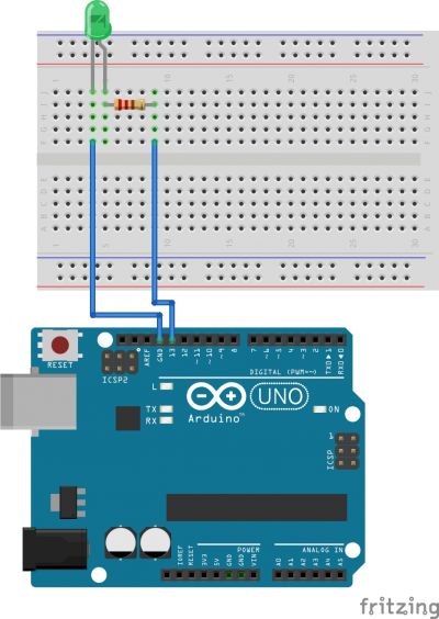
Connect the Pins following the scheme:
- Anode(+) of the LED (the longer leg) to Digital pin 13;
- Cathode(-) of the LED (the shorter leg) to Ground(GND);
You can connect this directly to the Ground Pin or you can connect it to any point the negative rail of the breadboard. This one that needs to be connected to the Ground pin. This last option is preferable in case you want to connect other LEDS or components that also need to be connected to the Ground pin.
Programming the LED
Now we are going to program the board to control the LED.To program your board you can use Arduino's own software that allows use to write code and upload it on the board.
+ Open the Arduino software
You can open the Arduino IDE software on the computer. This is already installed in WH.02.108 and most of the computers at the Interaction Station. If you want you can also use it on your laptop, you can install it thought
this link.
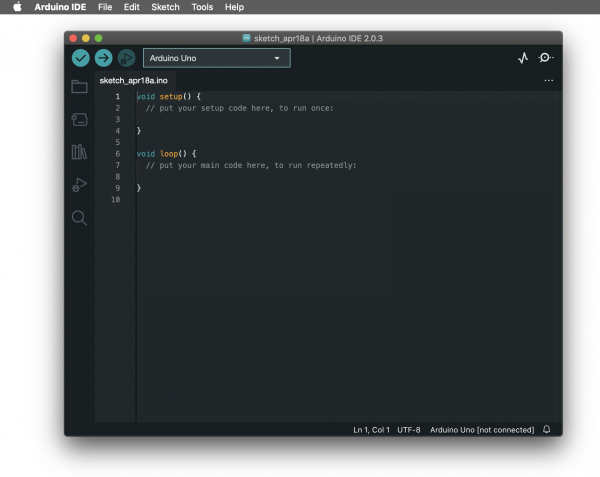
It should look like this:
+ Connect the board
You can now connect the board to the computer: this will enable us to upload the sketch as well as to power the board.
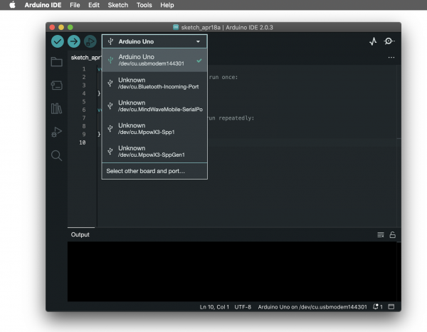
If the software found your board your will see it on the bottom right corner. If not, it will show [not connected].
To make select the board and the port you can go to Tools>Board and select your Arduino model, in our case is the Arduino Uno. To check if the right port is selected you can go to Tools>Port and select it. Often the software recognises it already and puts the board name between () after the port name.
In the new version of Arduino you can see board and port directly on your sketch window.
Turn on the LED
void setup() {
  // put your setup code here, to run once:
  pinMode(13, OUTPUT);
  digitalWrite(13, HIGH); // turn LED on (output 5V)
}

void loop() {
  // put your main code here, to run repeatedly:

}
Blinking LED
void setup() {
  // put your setup code here, to run once:
  pinMode(13, OUTPUT);
}

void loop() {
  // put your main code here, to run repeatedly:
    digitalWrite(13, HIGH); // turn LED on (output 5V);
    delay(500);
    digitalWrite(13, LOW); // turn LED on (output 5V);
    delay(500);
}
!!!!Note:
The delay() function pauses the program for an amount of time expressed in milliseconds.
For reference, 1000 milliseconds = 1 second.
Fading LED
int led = 9;         // the PWM pin the LED is attached to
int brightness = 0;  // how bright the LED is
int fadeAmount = 5;  // how many points to fade the LED by

void setup() {
  // put your setup code here, to run once:
  // declare pin 13 to be an output:
  pinMode(led, OUTPUT);
}

void loop() {
  // put your main code here, to run repeatedly:
  // set the brightness of pin 9:
  analogWrite(led, brightness);

  // change the brightness for next time through the loop:
  brightness = brightness + fadeAmount;

  // reverse the direction of the fading at the ends of the fade:
  if (brightness <= 0 || brightness >= 255) {
    fadeAmount = -fadeAmount;
  }
  // wait for 30 milliseconds to see the dimming effect
  delay(30);
}
!!!!Note:
AnalogWrite() uses pulse width modulation (PWM), turning a digital pin on and off very quickly with different ratios between on and off, to create a fading effect. The fading effect is possible to achieve only when using the PWM (Pulse with modulation) Pins. On most Arduino, the PWM pins are identified with a "~" sign. For this reason we moved the LED on Pin 9.
LEDs traffic light
What is you want to connect more than one LED?
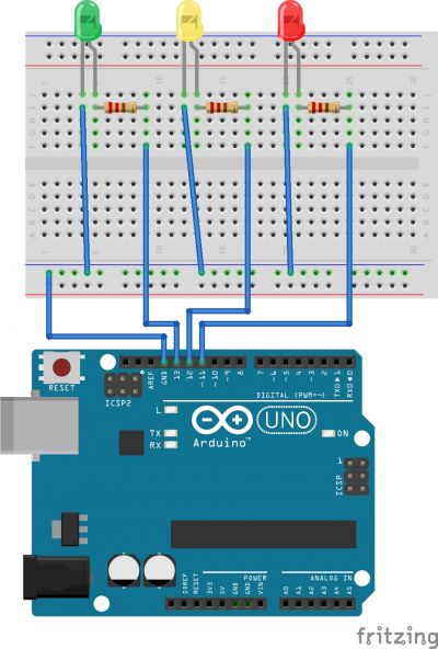
int greenLed = 13;
int yellowLed = 12;
int redLed = 11;

void setup() {
  // put your setup code here, to run once:
  pinMode(greenLed, OUTPUT);
  pinMode(yellowLed, OUTPUT);
  pinMode(redLed, OUTPUT);
}

void loop() {

  // put your main code here, to run repeatedly:
    //turn green light on for 3 seconds
    digitalWrite(greenLed, HIGH);
    delay(3000);
    //turn off green light and turn yellow light on for half a second
    digitalWrite(greenLed, LOW); // turn LED on (output 5V);
    digitalWrite(yellowLed, HIGH);
    delay(500);
    //turn off yellow light and turn on red light for 3 seconds
    digitalWrite(yellowLed, LOW); // turn LED on (output 5V);
    digitalWrite(redLed, HIGH);
    delay(3000);
    digitalWrite(redLed, LOW);

}
LED Morse code
Light can also be used to brighten an area or an object but can also be used to send messages. We will try to make our LED talk with the help of an old times favourite: Morse code.
Here is the reference:
Morse code reference

Letters
A .-
B -...
C -.-.
D -..
E .
F ..-.
G --.
H ....
I ..
J .---
K -.-
L .-..
M --
N -.
O ---
P .--.
Q --.-
R .-.
S ...
T -
U ..-
V ...-
W .--
X -..-
Y -.--
Z --..
Numbers
0 -----
1 .----
2 ..---
3 ...--
4 ....-
5 .....
6 -....
7 --...
8 ---..
9 ----.
Punctuation
Period           (.) .-.-.-
Comma            (,) --..--
Question Mark    (?) ..--..
Apostrophe.      (') .----.
Exclamation Mark (!) -.-.--
Prosigns
Starting signal      -.-.-
End of work          ...-.-
New message follows  .-.-.
Since Morse Code is just a combination of dots(.) and dashes (-) we can convert this graphical elements into time units.
dot(.) = 1 unit = 1 second
dash(-) = 3 units = 3 seconds
The space between parts of a letter in 1 unit = 1 second
The space between letters in 3 units = 3 second
The space between words is 7 units = 7 seconds
</div
Resources/More
physical computing Arduino page Arduino functions reference page more leds : series parallel circuit, calculating resistance laws blabla
Session 2
Arduino and LED strips
Examples of work
Types of strips
addressable, rgb, one color
