Arduino & Relays
The Conrad relay modules in the Station require higher that 5V voltage to operate, so we will use a 9V battery as a power source and switch it with an Arduino trough a BC547 transistor.
The modules look like this
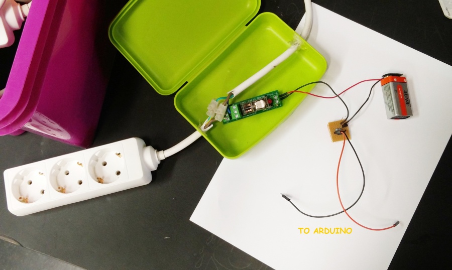
On the printed pcb modules there is a small separate circuit, where the transistor is.
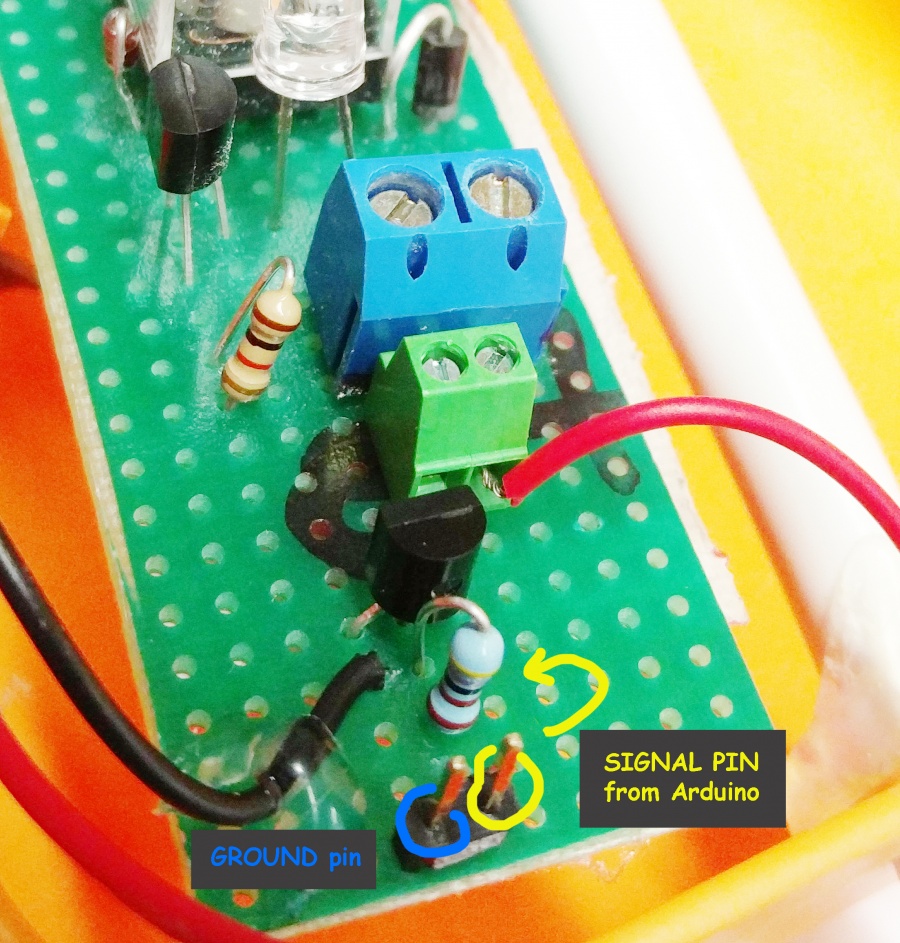
the small circuit looks like this in detail
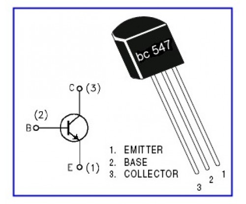
This is the BC547 pinout
The Arduino is connected trough a resistor to the Base of the Transistor.
SO the signal is to be connected onto the pin that is next to the resistor (look above)
When the Arduino pin is High, then voltage flows from the Emitter to the Collector, therefore it switches the relay on trough the battery.
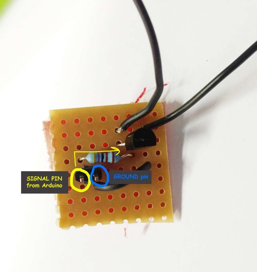
There are some boards that are not printed PCBs. They look like this
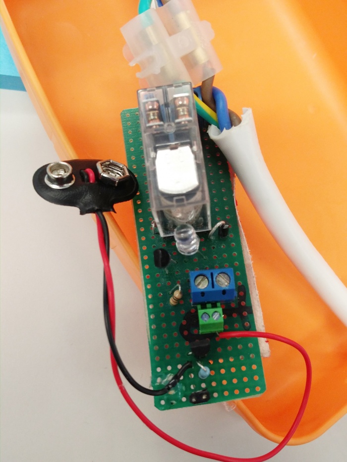
The transistor is placed directly on the board in this case. The logic is the same. Looks like this (always check the resistor from the Base, the pin it is connected to is the Arduino pin)
