Wearables: First Steps
Intro
This is an introduction to working with soft electronics.Combining and entwining circuits and fabrics. We will go trough the fundamental knowledge of electricity and how we can use it in various ways to make soft interfaces.
Materials
conductive
resistive
non-conductive
Tools
sewing machine
multimeter
pliers
scissors
lasercutter
vinyl cutter
3d printer
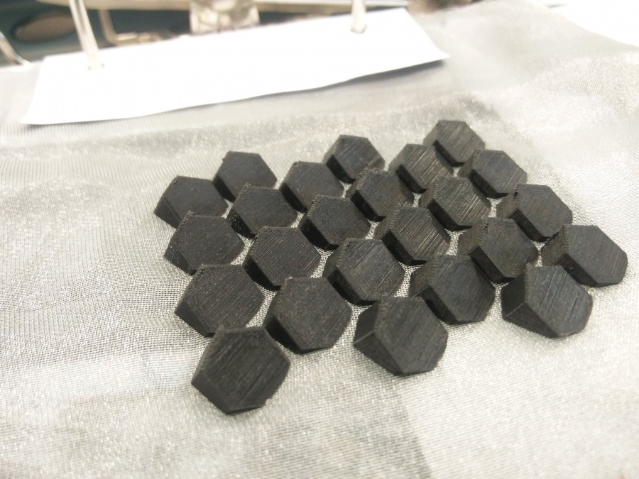
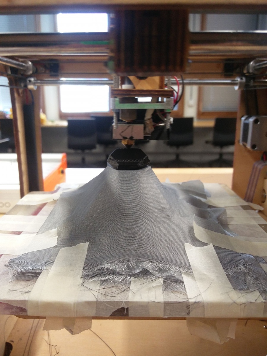
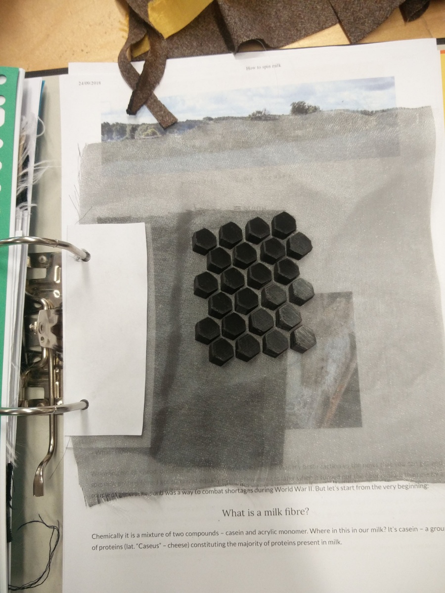
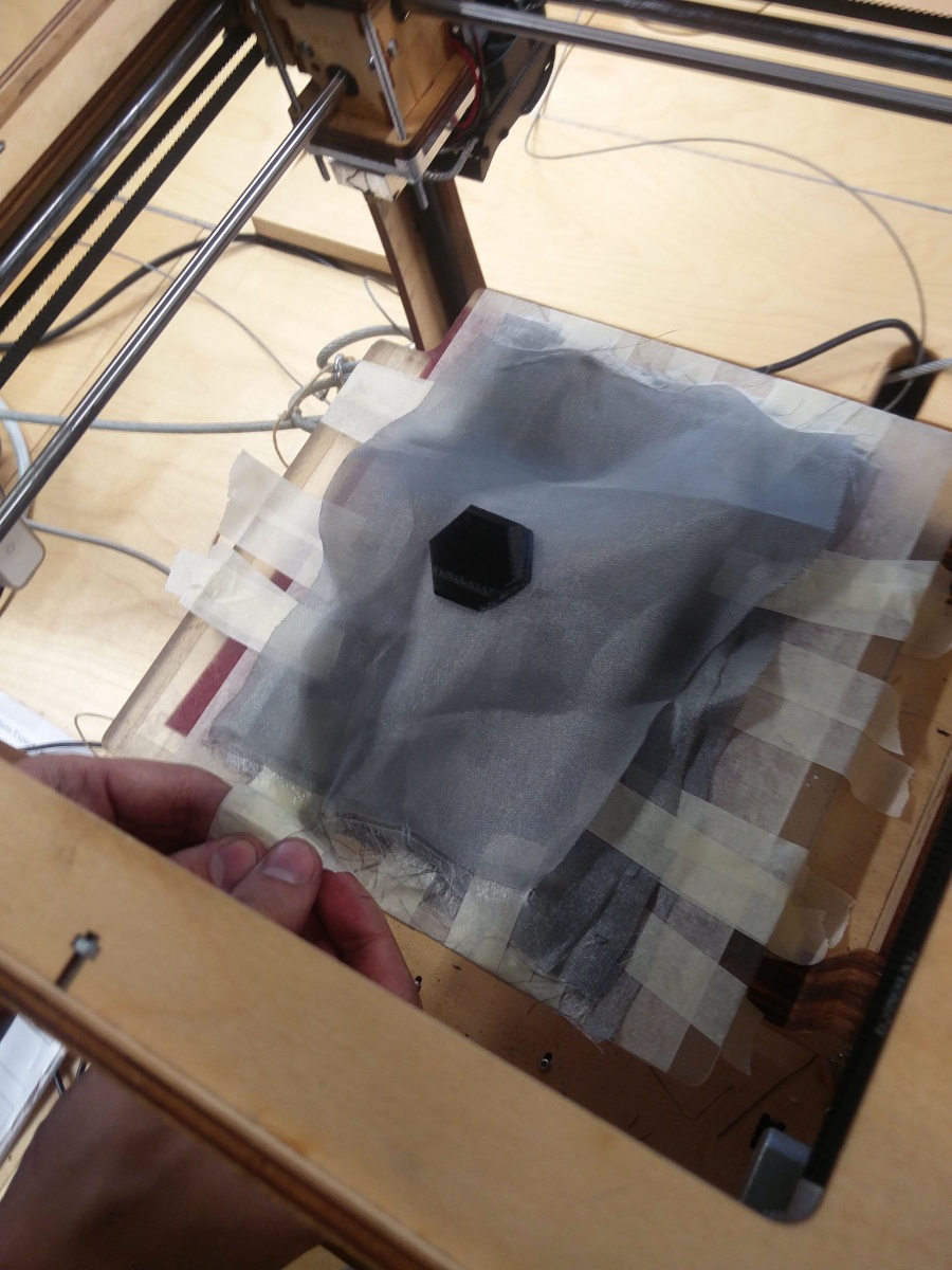
Material Research / 3D Printing over fabric
breadboard
microcontroller
arduino
flora
Hello wolrd: Soft circuit
For the hello world we will use an led as an output.
A light-emitting diode (LED) is a two-lead semiconductor light source. When a suitable voltage is applied to the leads, electrons are able to recombine with electron holes within the device, releasing energy in the form of photons. (https://en.wikipedia.org/wiki/Light-emitting_diode)
There are two things we have to take care when using LED.
– LED has polarity. Make sure to connect LED in correct direction.
You can tell the direction as the positive side usually has a longer leg, or a smaller triangle lead in the epoxy lens. Or a dent in the epoxy on the negative side.
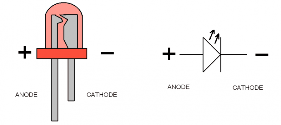 How much voltage and current does LEDs require to light up?
It depends on the LED and you will need to check its datasheet to know exact specification. The voltage you need is called “(forward) voltage drop” and the current required is called “forward current”. Most of the normal (not super bright) LEDs light up somewhere around 2-2.5v and require 20-30mA.
– You will need to limit the current to suitable range. you can read here “why?” >> To limit the current, you need to add resisters in your circuit. You can calculate it yourself using Ohm’s law, or use online calculators like this one >> http://led.linear1.org/1led.wiz
simple
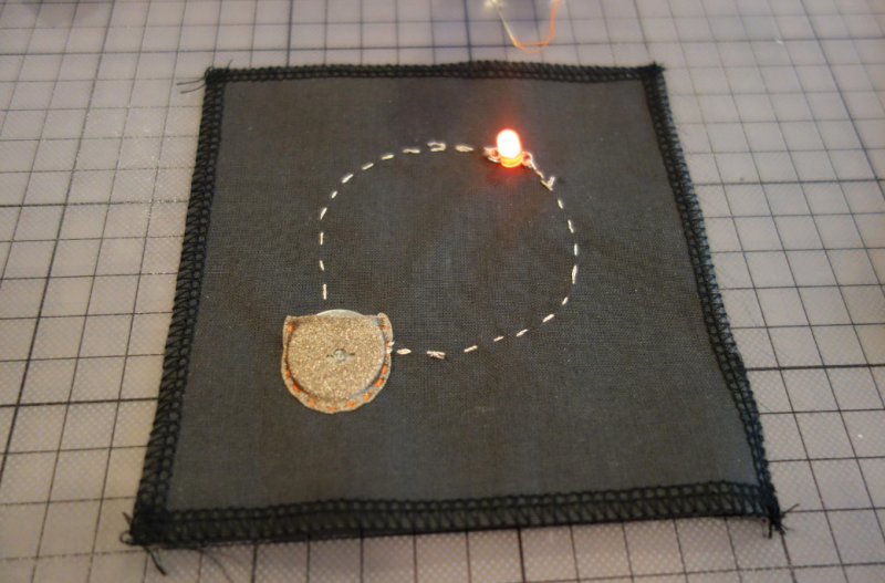
Lets s start my making the hello world of soft and any kind of circuitry:) And use the led we talked so much about.
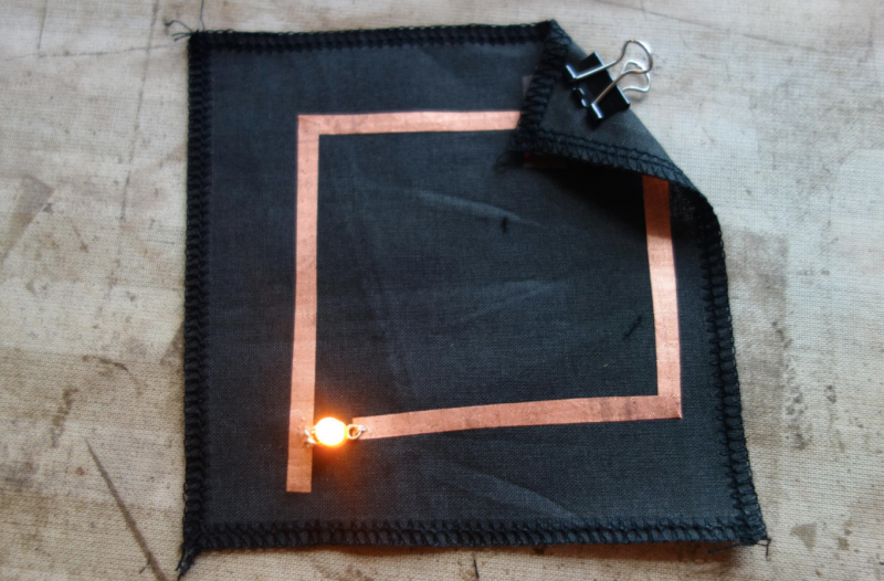
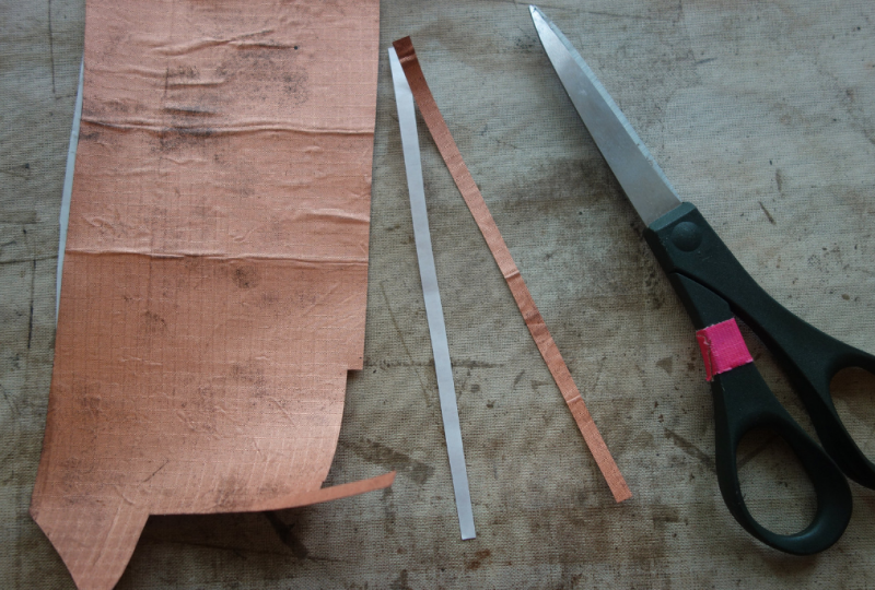
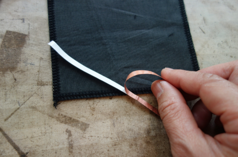
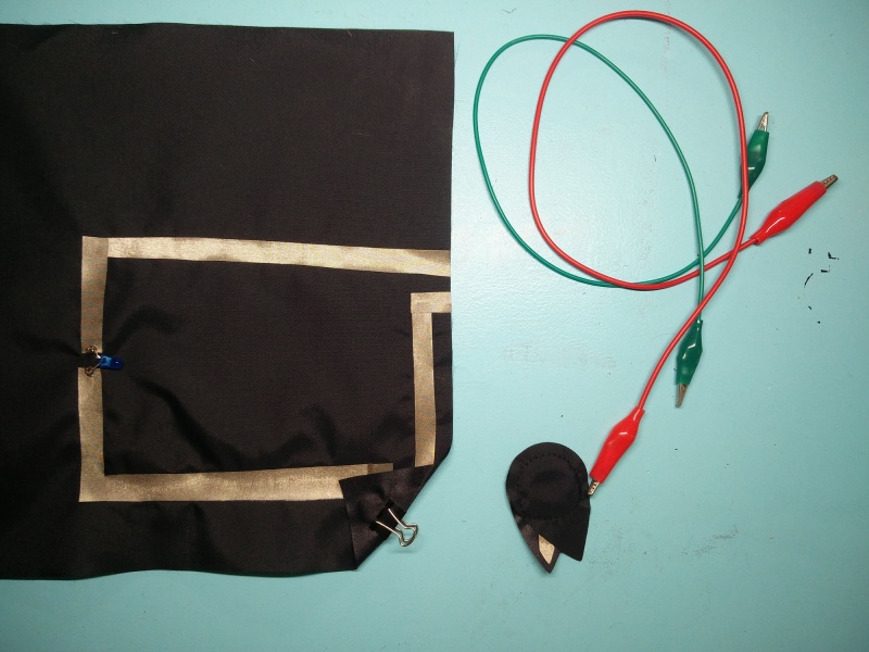
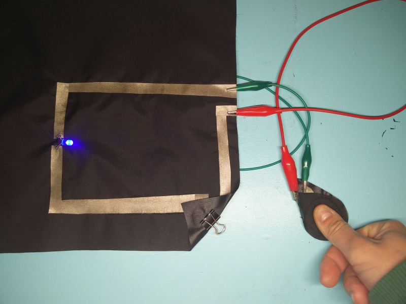
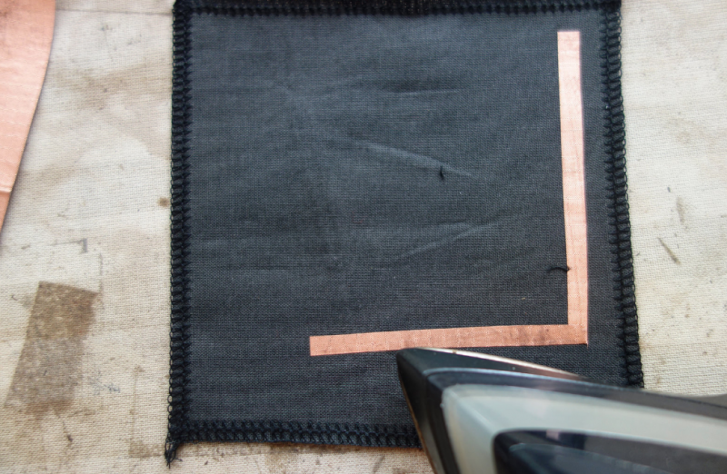
Cut conductive fabric that has fusible interfacing on one side. peel off the backing paper and place it on base fabric. Make sure the iron is set to synthetic. Most conductive fabric is delicate. And you do also rist the glue from the interfacing glue to appear of the front.
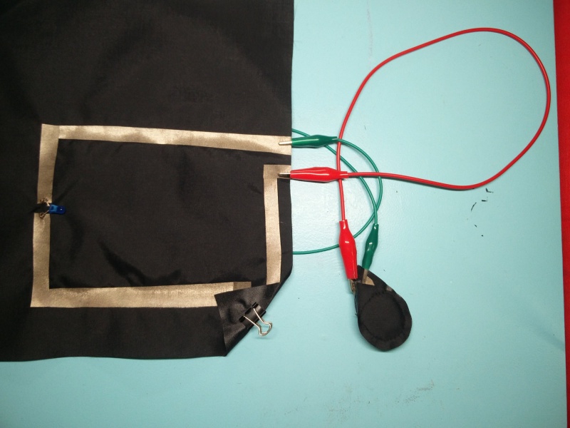
You can cut each side or fold to make corners. In both cases we need to check if all connections are right. We will use the continuity setting.
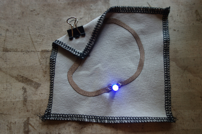
We make a rectangular shape and leave both sides open. On one side we will clamp the battery, and on the other: sew the led.
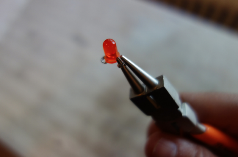
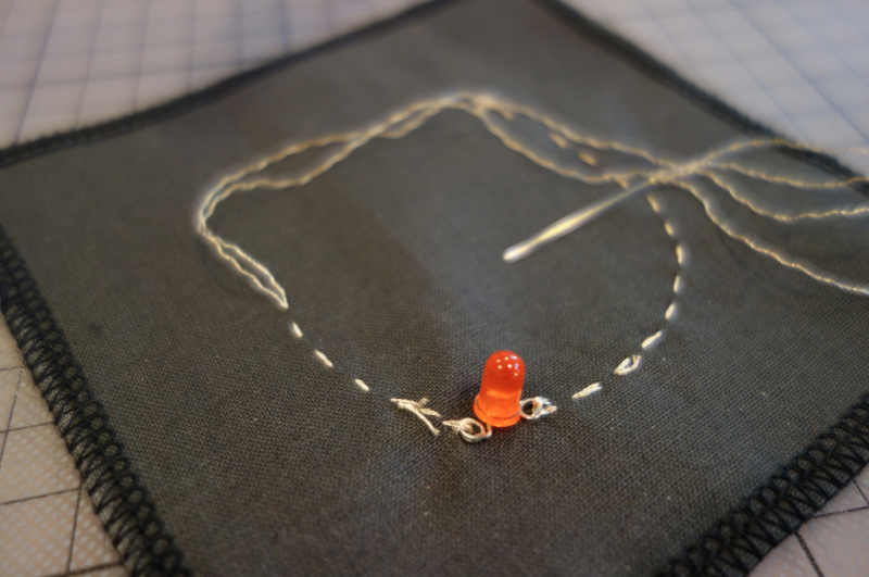
Use pliers ( best rounf ones) to bend the led legs into hooks. That way it will be easy to sew.
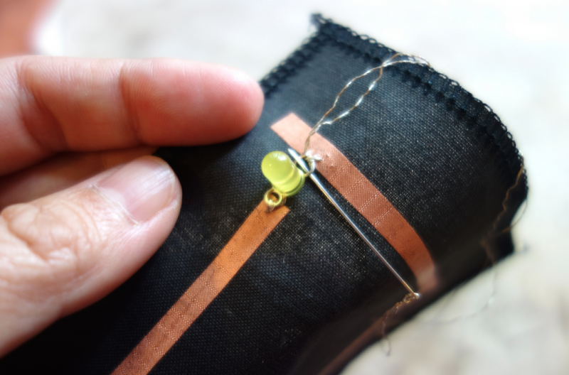
Then we will use a clip to hold the battery in place.

Many options are possible of course. Both in materials and design. But we have to get started,
You can also use conductive thread to make the circuit.
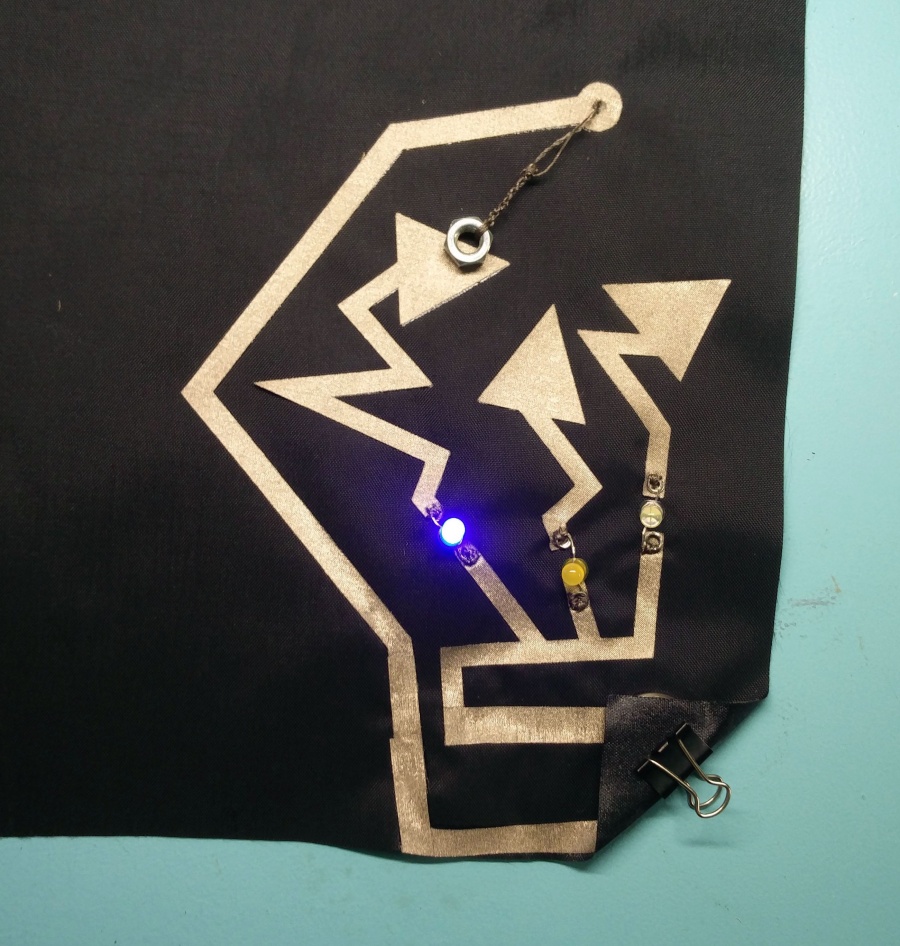
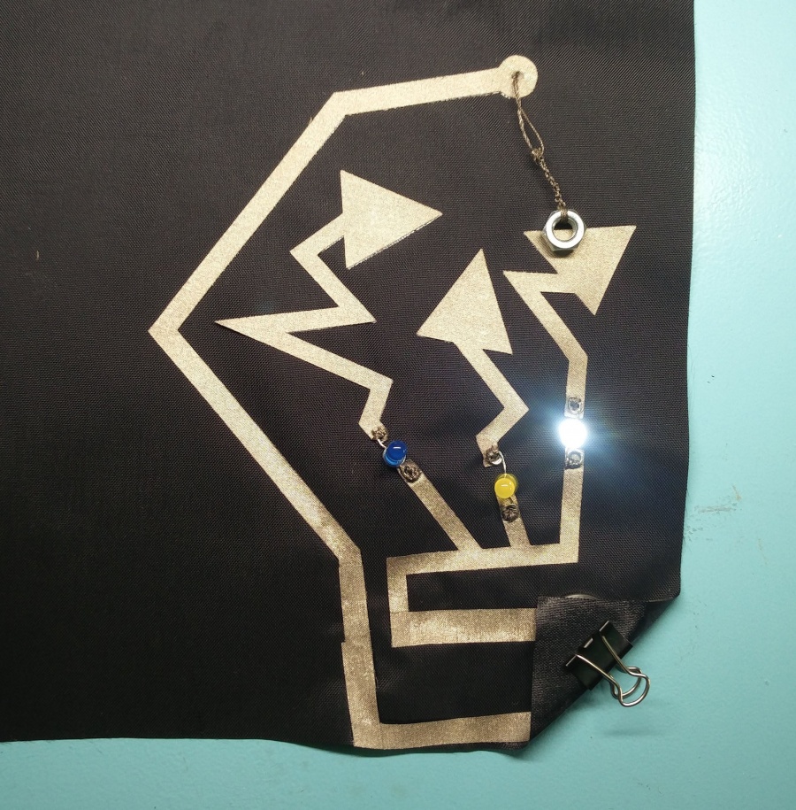
with button
But be fore we start. Lets make the push button.
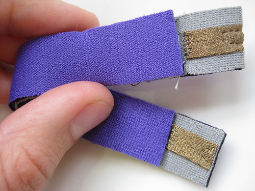
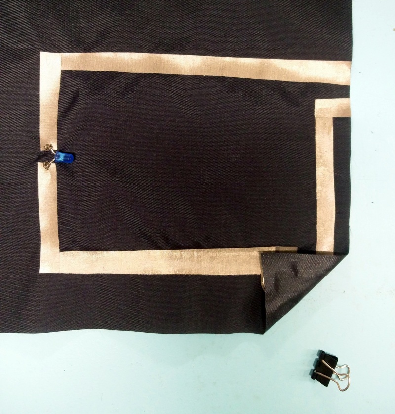
Here is the Kobakant push button. we have this kit and we have also some vinyl cut fabric.
Conductivity
Resistance
Sensors
Digital Sensors
Digital sensors are the sensors that gives 2 state (on/off, 5V/0V). You will connect them to digital Pins and set it as INPUT.
Digital data consists exclusively of 0s and 1s .
For example, consider a push button switch. This is one of the simplest forms of sensors. It has two discrete values. It is on, or it is off. Other 'discrete' sensors might provide you with a binary value.
Another example of a digital sensor is an accelerometer, which sends a series of data points (speed, direction, and so on) to the Arduino. Usually digital sensors need a chip in the sensor to interpret the physical data.
Analog Sensors
Analog sensors on the other hand, gives range. You connect this types of Analog sensors to Analog Input pins which is measuring the incoming voltage between 0V-5V*. Arduino converts this incoming voltage into the number between 0-1023.
Analog data is transmitted as a continuous signal, almost like a wave. In other words, an analog sensor doesn’t send a burst of 1s and 0s like digital sensors do; instead, the sensor modulates a continuous signal to transmit data.
Bend
Lets start by making the sticky tape sensor. Lets tape it
We have this kit at the Station [2] and it is very easy to build on our own
Tilt
EMF amp ( powerline sniffer)
Make your own
Microcontrolling it
digitalRead our button
[CLICK]
analogRead our bend sensor
Votage Dividers
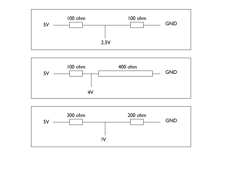
If you have 2 exactly same resistors, the voltage gets half in the middle, like the first diagram. As the ratio between two resisters changes, the voltage you get in the middle (between the resisters) changes accordingly.
One can calculate this by
Supply voltage (5v) x resistanceA / (resistanceA + resistanceB) = divided voltage
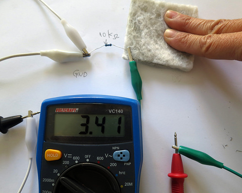
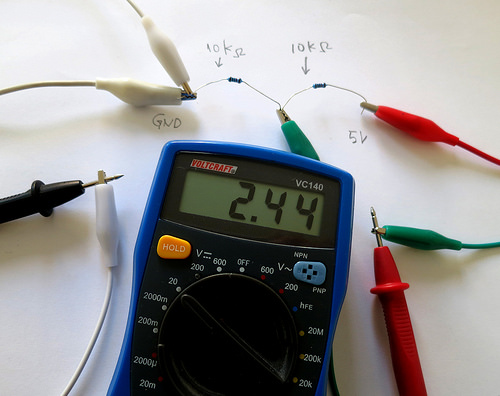
So much of a theory, let’s try this to see if it really works. Here is an experiment with two resister with a multumeter. The first experiment shows two same size resister (10kohm) dividing the provided voltage (5V) in half. The multimeter is set as V– for reading direct current voltage. The probes are connected to 0V (GND) of the power supply and the middle point where two resisters meet. You can see 2.44 in the multilmeter’s display. (almost 2.5V.. maybe the resister had some range) It divides the 5V in 50/50 ratio. Divider02.jpg
In the second experiment, I changed one of the resister to 47kohm. So now the ratio of two resisters are 10/47. So, I should read 5V x 10/(10+47) = 0.877 V in theory. As you can see in multimeter, it is 0.85V it measures. Not bad!
Now, if you change one of the resister to our resistive textile sensor, it works the same. The felt sensor I tested here has about 8kohm – 100kohm resistance range. You can see how the voltage that gets divided in the middle changes as I manipulate the felt. Now, if you connect the point where multimeter is reading to the arduino Analog input, we can read how much voltage comes in.
