Debugging electronics
Intro
As a test circuit we will build our own continuity tester, using the 555 timer IC
Always check first
- do you understand the schematic (or image)
- power
- connections (soldered or breadboarded)
- polarities
Understanding schematics
Breadboarding and breadboard debugging
OK, first, what's with the name....bread board? Bread, like in food?
Well yes, kind of.
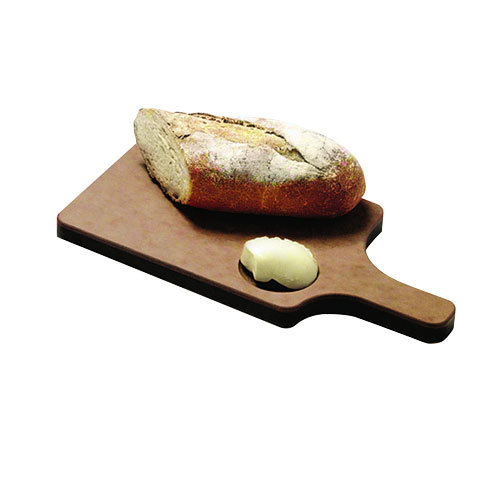
This terminology goes way back in the days.
Generally, you would mount electronic components to a piece of wood (the actual "breadboard"), and do all the wiring with point-point wire and the components just hanging between the various devices.
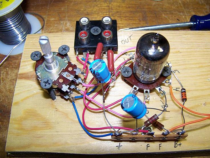
The story goes that an engineer had an idea for a vacuum tube device late one night. Looking around the house, the only base for his prototype that he found was indeed his wife's breadboard, from the breadbox.
A video by the Make magazine people
Ok, but why do we need to breadboard?
Well, they are useful for making temporary circuits and prototyping, and they require absolutely no soldering.
Prototyping is the process of testing out an idea by creating a preliminary model from which other forms are developed or copied, and it is one of the most common uses for breadboards.
The best way to explain how a breadboard works is to take it apart and see what’s inside.
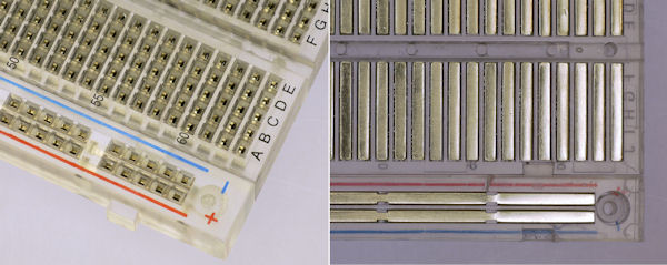
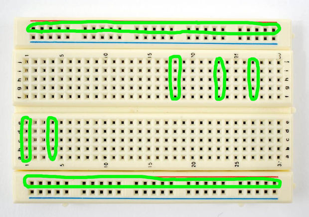
connections lines are connected like this
