|
|
| (23 intermediate revisions by 3 users not shown) |
| Line 2: |
Line 2: |
| | [[Physical computing]] | | [[Physical computing]] |
| | | | |
| − | | + | =[[example of projects]]= |
| | | | |
| | =Basic electronics and circuits= | | =Basic electronics and circuits= |
| − | == Electricity! ==
| + | [[Basic electronic components and sensors]] |
| | | | |
| − | [[file:AC-DC.jpg|600px]]<br>
| + | =Arduino introduction= |
| − | There are two types of electrical signals, being alternating current (AC), and direct current (DC).
| + | <br> |
| | + | Arduino is an open-source physical computing platform based on a simple input/output (I/O) board and a development environment that implements the Processing language. Arduino can be used to develop standalone interactive objects |
| | + | or can be connected to software on your computer.<br> |
| | + | What Is Physical Computing? |
| | + | Physical Computing uses electronics to prototype new materials for designers and artists. |
| | + | <br> |
| | + | Arduino is composed of two major parts: the Arduino board, which is the piece of hardware you work on when you build your objects; and the Arduino IDE, the piece of software you run on your computer. You use the IDE to create |
| | + | a sketch (a little computer program) that you upload to the Arduino board. The sketch tells the board what to do. |
| | | | |
| − | With alternating current, the direction electricity flows throughout the circuit is constantly reversing. <br>
| + | In the meantime, [https://www.arduino.cc/ HERE] you can find ANYTHING about Arduino, including download the software |
| − | You may even say that it is an alternating direction. The rate of reversal is measured in Hertz, which is the number of reversals per second.<br>
| |
| − | So, when they say that the US power supply is 60 Hz, what they mean is that it is reversing 120 times per second (twice per cycle).<br>
| |
| − | With Direct Current, electricity flows in one direction between power and ground. In this arrangement, <br>
| |
| − | there is always a positive source of voltage and ground (0V) source of voltage. You can test this by reading a battery with a multimeter.
| |
| | | | |
| − | Speaking of voltage, electricity is typically defined as having a voltage and a current rating. <br>
| + | NOW, |
| − | Voltage is obviously rated in Volts and current is rated in Amps. For instance, <br>
| |
| − | a brand new 9V battery would have a voltage of 9V and a current of around 500mA (500 milliamps).
| |
| | | | |
| − | Electricity can also be defined in terms of resistance and watts. We will talk a little bit about resistance in the next step, <br>
| + | [[File:Arduino-uno.png|700px]] |
| − | but I am not going to be going over Watts in depth. As you delve deeper into electronics you will encounter components with Watt ratings.<br>
| |
| − | It is important to never exceed the wattage rating of a component, but fortunately, that Wattage of your DC power supply can easily be calculated <br>
| |
| − | by multiplying the voltage and current of your power source.
| |
| | | | |
| − | If you want a better understanding of these different measurements, what they mean, and how they relate, <br>
| + | ==FIRST== |
| − | check out this [[https://www.youtube.com/watch?v=_-jX3dezzMg/ informative video]] on Ohm's Law.
| |
| | | | |
| − | [[File:Ohm-2527s-Law-funny-Explanation.jpg| 300 px]]
| + | we start by figuring put if our Arduino is all good or it is somehow damaged ...it is a basic test to check and run a simple script at the same time. |
| | | | |
| − | Watts = Volts x Amps
| + | === Go to File ---> Examples ---> Basics --->Blink === |
| | + | so we have something like this |
| | | | |
| − | Voltage= Current× Resistance. V= I×R.
| + | <syntaxhighlight lang=c style="border:3px dashed blue"> |
| | + | /* |
| | + | Blink |
| | + | Turns on an LED on for one second, then off for one second, repeatedly. |
| | | | |
| − | == Circuits ==
| + | Most Arduinos have an on-board LED you can control. On the Uno and |
| | + | Leonardo, it is attached to digital pin 13. If you're unsure what |
| | + | pin the on-board LED is connected to on your Arduino model, check |
| | + | the documentation at http://www.arduino.cc |
| | | | |
| − | [[file:Open-closed circuit .jpg]]
| + | This example code is in the public domain. |
| | | | |
| − | A circuit is a complete and closed path through which electric current can flow. In other words, a closed-circuit would allow the flow of electricity between power and ground. An open circuit would break the flow of electricity between power and ground.
| + | modified 8 May 2014 |
| | + | by Scott Fitzgerald |
| | + | */ |
| | | | |
| − | Anything that is part of this closed system and that allows electricity to flow between power and ground is considered to be part of the circuit.
| |
| | | | |
| − | == Resistance & short circuits ==
| + | // the setup function runs once when you press reset or power the board |
| | + | void setup() { |
| | + | // initialize digital pin 13 as an output. |
| | + | pinMode(13, OUTPUT); |
| | + | } |
| | | | |
| | + | // the loop function runs over and over again forever |
| | + | void loop() { |
| | + | digitalWrite(13, HIGH); // turn the LED on (HIGH is the voltage level) |
| | + | delay(1000); // wait for a second |
| | + | digitalWrite(13, LOW); // turn the LED off by making the voltage LOW |
| | + | delay(1000); // wait for a second |
| | + | } |
| | + | </syntaxhighlight> |
| | | | |
| − | In the circuit above, the LEDs that electricity is flowing through is adding resistance to the flow of electricity. Thus, all of the electricity passing through the circuit is being put to use.
| + | GOOOD! lets dissect this |
| | | | |
| − | In other words, there needs to be something wired between positive and ground that adds resistance to the flow of electricity and uses it up. If a positive voltage is connected directly to the ground and does not the first pass through something that adds resistance, like a motor, this will result in a short circuit. This means that the positive voltage is connected directly to the ground.
| + | * commenting / one line and multiple lines |
| | + | *setup |
| | + | *loop |
| | + | ===Choose board=== |
| | | | |
| − | Likewise, if electricity passes through a component (or group of components) that does not add enough resistance to the circuit, a short will likewise occur (see Ohm's Law video).
| + | [[File:Board.png | 800 px]] |
| | | | |
| − | '''Shorts are bad because they will result in your battery and/or circuit overheating, breaking, catching on fire, and/or exploding.<br>'''
| + | ===Choose port === |
| | | | |
| − | '''It is very important to prevent short circuits by making sure that the positive voltage is never wired directly to the ground.'''
| + | [[File:Port.png | 800 px]] |
| | | | |
| − | That said, always keep in mind that electricity always follows the path of least resistance to ground. What this means is that if you give positive voltage the choice to pass through a motor to ground, or follow a wire straight to ground, it will follow the wire because the wire provides the least resistance. This also means that by using the wire to bypass the source of resistance straight to the ground, you have created a short circuit. Always make sure that you never accidentally connect positive voltage to the ground while wiring things in parallel.
| |
| | | | |
| − | Also, note that a switch does not add any resistance to a circuit and simply adding a switch between power and ground will create a short circuit.
| |
| | | | |
| − | == Series Vs. Parallel == | + | ===''Lets compile this'' === |
| | + | --- Press/ Click upper most left button, looks like a '''Tick'''. Observe the messages appearing in the bottom of the Arduino software window ( there must be a sentence '''Done Compiling ''' <br> |
| | + | [[File:Compile.png|500px ]] |
| | | | |
| | | | |
| − | There are two different ways in which you can wire things together called series and parallel.<br>
| + | ===''Lets upload this'' === |
| − | [[file:Series-parallel-circuits-connected.jpg]]
| |
| | | | |
| − | When things are wired in series, things are wired one after another, such that electricity has to pass through one thing, then the next thing, then the next, and so on.
| + | [[File:Upload.png ]] <br> |
| | | | |
| − | In the left picture, the lightbulbs, switch, and battery are all wired in series because the only path for electricity to flow is from one to the next, and to the next.
| + | And we should have a Blinking aka Flashing on board LED |
| | | | |
| − | When things are wired in parallel, they are wired side by side, such that electricity passes through all of them at the same time, from one common point to another common point
| |
| | | | |
| − | In the next example, the lightbulbs are wired in parallel because the electricity passes through both lightbulbs from one common point to another common point.
| + | [[File:Arduino-LED-Overview.jpg | 700 px]] |
| | | | |
| − | If this does not make sense yet, do not worry. When you start to build your own circuits, all of this will start to become clear.
| + | ''OK, so your Ardiono blinks, that was ''Hello World!'''' |
| | | | |
| − | Series and Parallel Circuits have different resistance even with the same components.
| + | ==Simple circuits and sketches== |
| | | | |
| − | In Series Circuits the total resistance Rt=R1+R2
| + | Now let's try out some simple circuits and Arduino sketches: |
| | | | |
| − | In Parallel Circuits the total resistance will be smaller than Series Circuits: 1/Rt=(1/R1)+(1/R2)
| + | please find the pdf file on Teams. |
| | | | |
| − | [[calculating Total Resistance in Series and Parallel Circuits/https://www.youtube.com/watch?v=rwU6lT_yYoA]]
| + | or here: |
| | | | |
| − | == Basic Components ==
| + | http://interactionstation.wdka.hro.nl/mediawiki/images/a/ad/2nd-Arduino-Simple_circuits_and_sketches.pdf |
| − | [[file:BasicComponents.jpg]]
| |
| | | | |
| | + | ==microcontrollers== |
| | | | |
| − | === Resistors ===
| + | Computer and processor are generic terms for anything that can run a program, basically. |
| − | [[file:Resistors.jpg]]
| + | A controller or microcontroller usually refers to a simple processor that does only one task, like listening to sensors. |
| | + | In explaining microcontrollers, we’ll distinguish them from computers, which contain more powerful processors that can run an operating system. |
| | | | |
| − | As the name implies, resistors add resistance to the circuit and reduce the flow of electrical current. It is represented in a circuit diagram as a pointy squiggle with a value next to it.
| + | besides Arduino, there are also a lot of other microcontrollers available. |
| | | | |
| − | The different markings on the resistor represent different values of resistance. These values are measured in ohms.
| + | for example, we also have many Adafruit circuit playgrounds express and bluefruit at the interaction station. |
| | | | |
| − | Resistors also come with different wattage ratings. For most low-voltage DC circuits, 1/4 watt resistors should be suitable.
| + | You can also program them with Arduino IDE. |
| | | | |
| − | You read the values from left to right towards the (typically) gold band. The first two colors represent the resistor value, the third represents the multiplier, and the fourth (the gold band) represents the tolerance or precision of the component. You can tell the value of each color by looking at a resistor color value chart.
| + | Check out this link: |
| | | | |
| − | Or... to make your life easier, you could simply look up the values using a [[http://www.dannyg.com/examples/res2/resistor.htm/'''graphical resistance calculator''']].
| + | [[workshop one| circuit playgrounds express ]] |
| | | | |
| − | Anyhow... a resistor with the markings brown, black, orange, gold will translate as follows:
| + | =Sensors and Actuators= |
| | + | ==Sensing== |
| | + | we often construct our reality using our sensory experience: |
| | | | |
| − | 1 (brown) 0 (black) x 1,000 = 10,000 with a tolerance of +/- 5%
| + | our visual and sound come from our eyes and ears, we can feel the moisture level on our skins, we can feel the gravity and orientation thanks to our inner ear structures. |
| | | | |
| − | Any resistor of over 1000 ohms is typically shorted using the letter K. For instance, 1,000 would be 1K; 3,900, would translate to 3.9K; and 470,000 ohms would become 470K.
| + | and now imagine all the sensory input can be converted into digits and feed to a computer, and the computer device can decide what to do(output) with the input data. |
| | + | let's look back to the Shannon-Weaver model of communication. |
| | | | |
| − | Values of ohms over a million are represented using the letter M. In this case, 1,000,000 ohms would become 1M.
| |
| | | | |
| − | === Capacitors ===
| + | there is so many already made sensor module for Arduino. Many sensors can detect signals or pick up data beyond human senses. For example ultrasonic sensors. |
| − | [[file:Capacitors.jpg]]
| + | Imagine we can use these sensor technologies to expand our senses and "reality". |
| | | | |
| − | A capacitor is a component that stores electricity and then discharges it into the circuit when there is a drop in electricity. You can think of it as a water storage tank that releases water when there is a drought to ensure a steady stream.
| + | Back to the Sensors: |
| | + | In General, there are two types of sensors: analog and digital. |
| | | | |
| − | for more info [[capacitors]] | + | The analog sensor can detect a range of data. (for example from 0-1020) |
| | | | |
| − | === Diodes ===
| + | The digital sensor can detect either 0 or 1. (or HIGHT /LOW). |
| | | | |
| − | [[file:Diode.jpg]]
| + | for better understanding: the analog sensor is like a dimmer and the digital sensor is like a normal switch. |
| | | | |
| − | Diodes are components which are polarized. They only allow electrical current to pass through them in one direction. This is useful in that it can be placed in a circuit to prevent electricity from flowing in the wrong direction.
| + | Here is a list of sensors and examples: |
| | | | |
| − | more info [[Diodes]]
| + | [['''Comment sensors:''']] |
| | + | Don't need additional libraries, normally included in Arduino's example tutorials.<br> |
| | + | Potential meters: [https://www.arduino.cc/en/Tutorial/AnalogReadSerial AnalogReadSerial] |
| | + | Botton or switch: [https://www.arduino.cc/en/Tutorial/Button Button] |
| | + | Ultrasonic sensor: [https://www.arduino.cc/en/Tutorial/Ping Ping] |
| | + | Mic or piezo: [https://www.arduino.cc/en/Tutorial/Knock knock] |
| | + | [https://www.arduino.cc/en/Tutorial/toneMultiple toneMultiple] |
| | | | |
| − | === Transistors ===
| + | Flex & force sensor: [https://www.arduino.cc/en/Tutorial/toneKeyboard toneKeyboard] |
| − | [[file:Transistors.jpg]] | + | LDR (Light Dependent Resistor): |
| | + | [https://www.arduino.cc/en/Tutorial/Calibration Calibration] |
| | + | [https://www.arduino.cc/en/Tutorial/tonePitchFollower tonePitchFollower] |
| | | | |
| − | A transistor takes in a small electrical current at its base pin and amplifies it such that a much larger current can pass between its collector and emitter pins. The amount of current that passes between these two pins is proportional to the voltage being applied at the base pin.
| + | [[ '''Advanced sensors:''']] |
| | + | Need to install additional libraries.<br> |
| | + | Capacitive Sensor-Analog : [https://learn.adafruit.com/adafruit-cap1188-breakout/using-with-arduino adafruit-cap1188-breakout] |
| | + | Or [https://www.bareconductive.com/shop/touch-board/ touch-board] |
| | + | Pulse sensor(heart rate): [https://pulsesensor.com/pages/installing-our-playground-for-pulsesensor-arduino pulsesensor] |
| | + | UV sensor: [https://learn.adafruit.com/adafruit-si1145-breakout-board-uv-ir-visible-sensor/overview uv-index-sensor] |
| | + | Gyroscope/acceleration meter:[https://learn.adafruit.com/adafruit-lsm9ds1-accelerometer-plus-gyro-plus-magnetometer-9-dof-breakout/arduino-code Gyroscope/acceleration] |
| | | | |
| − | more info [[Transistors]]
| + | ==Actuators with Adafruit Motor Shield== |
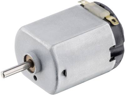
| | + | ===DC motor=== |
| | + | [[file:DC-motor.jpg]] |
| | | | |
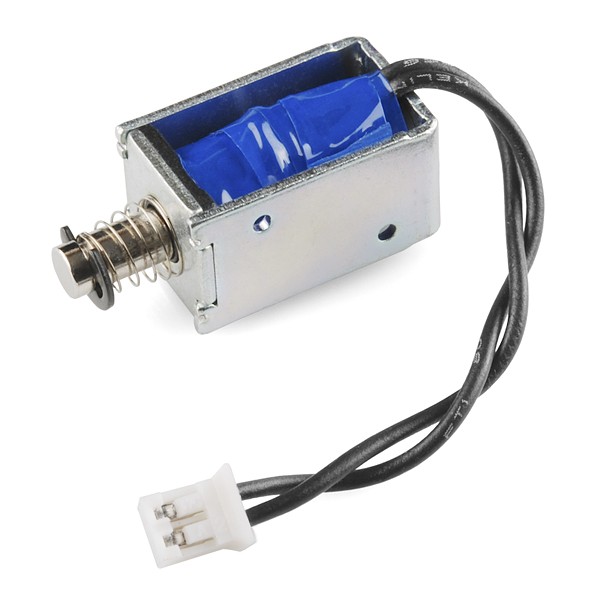
| − | === Potentiometers === | + | ===push-pull solenoid=== |
| | + | [[file:Solenoid-5v-small.jpg]] |
| | | | |
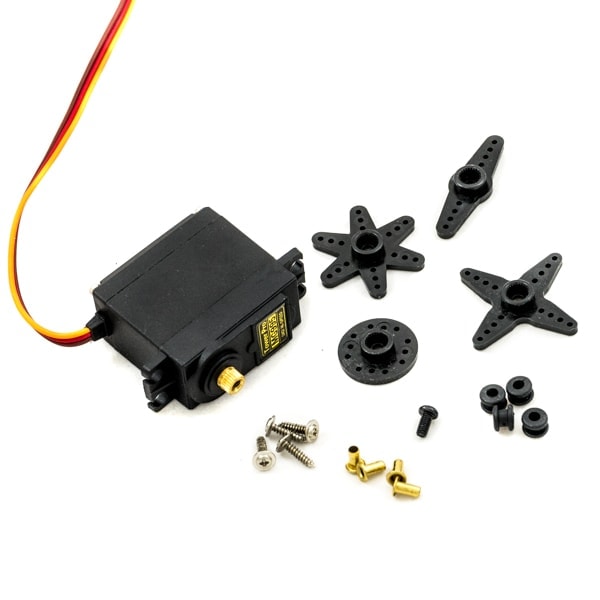
| − | [[file:Potentiometers.jpg]] | + | ===Servo motor=== |
| | + | [[file:Servo2.jpg]] |
| | | | |
| − | Potentiometers are variable resistors. In plain English, they have some sort of knob or slider that you turn or push to change resistance in a circuit. If you have ever used a volume knob on a stereo or a sliding light dimmer, then you have used a potentiometer.
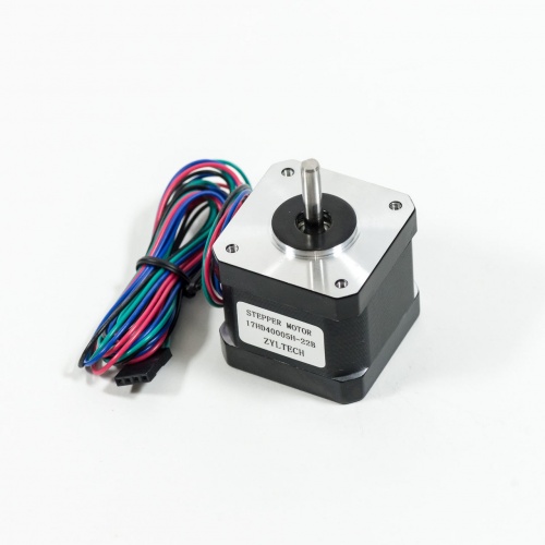
| + | ===Stepper motor=== |
| | + | [[File:Nema-17.jpeg| 500px]] |
| | | | |
| − | Potentiometers are measured in ohms like resistors, but rather than having color bands, they have their value rating written directly on them (i.e. "1M"). They are also marked with an "A" or a "B, " which indicated the type of response curve it has.
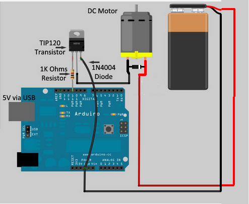
| + | ==TIP 120 circuit== |
| − | | + | Transistors are powerful little electronic switches, and when our little NPN transistors aren't powered enough for your project, we have been known to use these beefy TIP120 Darlington transistors. Great for whenever you need to control medium to high-power electronics such as motors, solenoids, or 1W+ LEDs. |
| − | Potentiometers marked with a "B" have a linear response curve. This means that as you turn the knob, the resistance increases evenly (10, 20, 30, 40, 50, etc.). The potentiometers marked with an "A" have a logarithmic response curve. This means that as you turn the knob, the numbers increase logarithmically (1, 10, 100, 10,000 etc.)
| |
| − | | |
| − | Potentiometers have three legs as to create a voltage divider, which is basically two resistors in series. When two resistors are put in series, the point between them is a voltage that is a value somewhere between the source value and ground.
| |
| − | | |
| − | For instance, if you have two 10K resistors in series between power (5V) and ground (0V), the point where these two resistors meet will be half the power supply (2.5V) because both of the resistors have identical values. Assuming this middle point is actually the center pin of a potentiometer, as you turn the knob, the voltage on the middle pin will actually increase towards 5V or decrease toward 0V (depending which direction that you turn it). This is useful for adjusting the intensity of an electrical signal within a circuit (hence its use as a volume knob).
| |
| − | | |
| − | This is represented in a circuit as a resistor with an arrow pointing towards the middle of it.
| |
| − | | |
| − | If you only connect one of the outer pins and the center pin to the circuit, you are only changing the resistance within the circuit and not the voltage level on the middle pin. This too is a useful tool for circuit building because often you just want to change the resistance at a particular point and not create an adjustable voltage divider.
| |
| − | This configuration is often represented in a circuit as a resistor with an arrow coming out of one side and looping back in to point towards the middle.
| |
| − | | |
| − | === LEDs === | |
| − | | |
| − | [[file:LEDs.jpg]]
| |
| − | | |
| − | LED stands for light emitting diode. It is basically a special type of diode that lights up when electricity passes through it. Like all diodes, the LED is polarized and electricity is only intended to pass through in one direction.
| |
| − | | |
| − | There are typically two indicators to let you know what direction electricity will pass through and LED. The first indicator that the LED will have a longer positive lead (anode) and a shorter ground lead (cathode). The other indicator is a flat notch on the side of the LED to indicate the positive (anode) lead. Keep in mind that not all LEDs have this indication notch (or that it is sometimes wrong).
| |
| − | | |
| − | Like all diodes, LEDs create a voltage drop in the circuit, but typically do not add much resistance. In order to prevent the circuit from shorting, you need to add a resistor in series. To figure out how large of a resistor you need for optimum intensity, you can use this online LED calculator to figure out how much resistance is needed for a single LED. It is often good practice to use a resistor that is slightly larger in the value than what is returned by [[http://led.linear1.org/1led.wiz/ calculator]].
| |
| − | | |
| − | '''Typically, the forward voltage of an LED is between 1.8 and 3.3 volts. It varies by the color of the LED. A red LED typically drops 1.8 volts.'''
| |
| − | '''For most purposes, the exact value is not critical and you can use 2V for red, yellow and green, or 4V for blue and white LEDs.'''
| |
| − | | |
| − | '''The LED current must be less than the maximum permitted for your LED. For standard 5mm diameter LEDs the maximum current is usually 20mA, '''
| |
| − | '''so 10mA or 15mA are suitable values for many circuits. The current must be in amps (A) for the calculation, to convert from mA to A divide the current in mA by 1000.'''
| |
| − | | |
| − | You may be tempted to wire LEDs in series, but keep in mind that each consecutive LED will result in a voltage drop until finally there is not enough power left to keep them lit. As such, it is ideal to light up multiple LEDs by wiring them in parallel. However, you need to make certain that all of the LEDs have the same power rating before you do this (different colors often are rated differently).
| |
| − | | |
| − | LEDs will show up in a schematic as a diode symbol with lightning bolts coming off of it, to indicate that it is a glowing diode.
| |
| − | | |
| − | ===Buttons and Switches ===
| |
| − | [[file:Switches.jpg]]
| |
| − | | |
| − | | |
| − | A switch is basically a mechanical device that creates a break in a circuit. When you activate the switch, it opens or closes the circuit. This is dependent on the type of switch it is.
| |
| − | | |
| − | Normally open (N.O.) switches close the circuit when activated.
| |
| − | | |
| − | Normally closed (N.C.) switches open the circuit when activated.
| |
| − | | |
| − | As switches get more complex they can both open one connection and close another when activated. This type of switch is a single-pole double-throw switch (SPDT).
| |
| − | | |
| − | If you were to combine two SPDT switches into one single switch, it would be called a double-pole double-throw switch (DPDT). This would break two separate circuits and open two other circuits, every time the switch was activated.
| |
| − | | |
| − | === Batteries and Power Supply===
| |
| − | [[file:Batteries.jpg]]
| |
| − | | |
| − | A battery is a container which converts chemical energy into electricity. To over-simplify the matter, you can say that it "stores power."
| |
| − | | |
| − | By placing batteries in series you are adding the voltage of each consecutive battery, but the current stays the same. For instance, a AA-battery is 1.5V. If you put 3 in series, it would add up to 4.5V. If you were to add a fourth in series, it would then become 6V.
| |
| − | | |
| − | By placing batteries in parallel the voltage remains the same, but the amount of current available doubles. This is done much less frequently than placing batteries in series, and is usually only necessary when the circuit requires more current than a single series of batteries can offer.
| |
| | | | |
| − | It is recommended that you get a range of AA battery holders. For instance, I would get an assortment that holds 1, 2, 3, 4, and 8 AA batteries.
| + | [[file:Tryitthisway.PNG]] |
| | | | |
| − | === Breadboards === | + | <syntaxhighlight lang="C" line='line'> |
| − | OK, first, what's with the name....bread board? Bread, like in food?
| + | void setup () |
| − | Well yes, kind of.
| + | { |
| − | <br> | + | pinMode(11, OUTPUT); |
| − | [[File:Breadboard.jpg ]]
| + | } |
| | + | |
| | + | void loop () |
| | + | { |
| | + | digitalWrite(11, 1); |
| | + | delay(2500); |
| | + | digitalWrite(11, 0); |
| | + | delay(2500); |
| | + | } |
| | + | </syntaxhighlight> |
| | | | |
| − | This terminology goes way back in the days.
| |
| − | Generally, you would mount electronic components to a piece of wood (the actual "breadboard"), and do all the wiring with point-point wire and the components just hanging between the various devices.
| |
| − | <br>
| |
| − | [[File:Breadboardreal.jpg]]
| |
| − | <br>
| |
| − | The story goes that an engineer had an idea for a vacuum tube device late one night. Looking around the house, the only base for his prototype that he found was indeed his wife's breadboard, from the breadbox.
| |
| − | <br>
| |
| − | [http://www.youtube.com/watch?feature=player_embedded&v=HrG98HJ3Z6w A video by the Make magazine people ]
| |
| − | <br>
| |
| − | Ok, but why do we need to breadboard?
| |
| − | <br>
| |
| − | '''Well, they are useful for making temporary circuits and prototyping, and they require absolutely no soldering.'''
| |
| − | <br>
| |
| − | '''Prototyping is the process of testing out an idea by creating a preliminary model from which other forms are developed or copied,'''
| |
| − | '''and it is one of the most common uses for breadboards.'''
| |
| − | <br>
| |
| − | The best way to explain how a breadboard works is to take it apart and see what’s inside.<br>
| |
| − | [[File:Breadboard02.jpg]]
| |
| − | <br><br>
| |
| − | connections lines are connected like this
| |
| − | <br>
| |
| − | [[File:Breadboard03.jpg]]
| |
| − |
| |
| − | <br>
| |
| − |
| |
| − | =Arduino introduction=
| |
| − | ==all about microcontrollers==
| |
| − | ==simple circuit and sketches==
| |
| − |
| |
| − | =Sensors and Actuators=
| |
| − | ==Sensing==
| |
| − |
| |
| − | ==Actuators with Adafruit Motor Shield==
| |
| − | ===DC motor===
| |
| − | ===push-pull solenoid===
| |
| − | ===Servo motor===
| |
| − | ===Stepper motor==
| |
| − | ==TIP 120 circuit==
| |
| | ==Relay Module== | | ==Relay Module== |
| | ''Introducing the Relay Module'' | | ''Introducing the Relay Module'' |
| Line 255: |
Line 214: |
| | | | |
| | | | |
| − | ==Wiring==
| + | '''Wiring''' |
| | [[File:1channel-relay-fritzing-1.jpg|500px]] | | [[File:1channel-relay-fritzing-1.jpg|500px]] |
| | | | |
| Line 264: |
Line 223: |
| | '''IN1''': controls the relay (it is connected to an Arduino digital pin)<br> | | '''IN1''': controls the relay (it is connected to an Arduino digital pin)<br> |
| | | | |
| − | '''OK, but maybe you want to control more than one thing??'''
| + | [[Category:2021]] |
| − | | |
| − | <br> then no porblem<br>
| |
| − | [[File:6-Channel-12V-Relay-Module.jpg|400px]] | |
| − | here are 16 channels:)
| |
| − | The wiring is the same, you will just need 16 digital pins on the Arduino
| |
Physical computing
Physical computing
Basic electronics and circuits
Basic electronic components and sensors
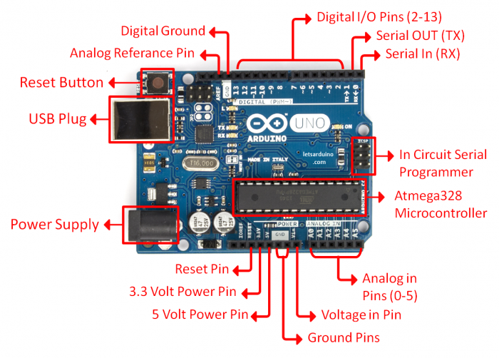
Arduino introduction
Arduino is an open-source physical computing platform based on a simple input/output (I/O) board and a development environment that implements the Processing language. Arduino can be used to develop standalone interactive objects
or can be connected to software on your computer.
What Is Physical Computing?
Physical Computing uses electronics to prototype new materials for designers and artists.
Arduino is composed of two major parts: the Arduino board, which is the piece of hardware you work on when you build your objects; and the Arduino IDE, the piece of software you run on your computer. You use the IDE to create
a sketch (a little computer program) that you upload to the Arduino board. The sketch tells the board what to do.
In the meantime, HERE you can find ANYTHING about Arduino, including download the software
NOW,
FIRST
we start by figuring put if our Arduino is all good or it is somehow damaged ...it is a basic test to check and run a simple script at the same time.
Go to File ---> Examples ---> Basics --->Blink
so we have something like this
/*
  Blink
  Turns on an LED on for one second, then off for one second, repeatedly.

  Most Arduinos have an on-board LED you can control. On the Uno and
  Leonardo, it is attached to digital pin 13. If you're unsure what
  pin the on-board LED is connected to on your Arduino model, check
  the documentation at http://www.arduino.cc

  This example code is in the public domain.

  modified 8 May 2014
  by Scott Fitzgerald
 */


// the setup function runs once when you press reset or power the board
void setup() {
  // initialize digital pin 13 as an output.
  pinMode(13, OUTPUT);
}

// the loop function runs over and over again forever
void loop() {
  digitalWrite(13, HIGH);   // turn the LED on (HIGH is the voltage level)
  delay(1000);              // wait for a second
  digitalWrite(13, LOW);    // turn the LED off by making the voltage LOW
  delay(1000);              // wait for a second
}
GOOOD! lets dissect this
- commenting / one line and multiple lines
- setup
- loop
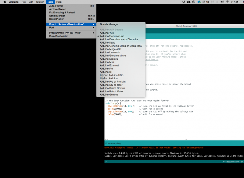
Choose board
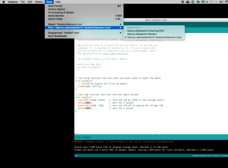
Choose port
Lets compile this
--- Press/ Click upper most left button, looks like a Tick. Observe the messages appearing in the bottom of the Arduino software window ( there must be a sentence Done Compiling
Lets upload this
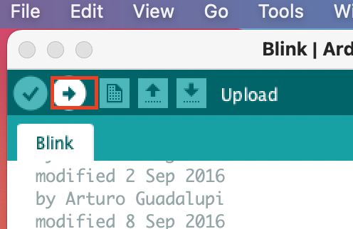
And we should have a Blinking aka Flashing on board LED
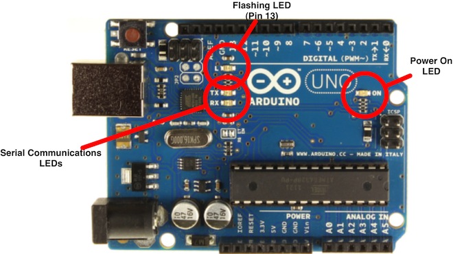
OK, so your Ardiono blinks, that was Hello World!'
Simple circuits and sketches
Now let's try out some simple circuits and Arduino sketches:
please find the pdf file on Teams.
or here:
http://interactionstation.wdka.hro.nl/mediawiki/images/a/ad/2nd-Arduino-Simple_circuits_and_sketches.pdf
microcontrollers
Computer and processor are generic terms for anything that can run a program, basically.
A controller or microcontroller usually refers to a simple processor that does only one task, like listening to sensors.
In explaining microcontrollers, we’ll distinguish them from computers, which contain more powerful processors that can run an operating system.
besides Arduino, there are also a lot of other microcontrollers available.
for example, we also have many Adafruit circuit playgrounds express and bluefruit at the interaction station.
You can also program them with Arduino IDE.
Check out this link:
circuit playgrounds express
Sensors and Actuators
Sensing
we often construct our reality using our sensory experience:
our visual and sound come from our eyes and ears, we can feel the moisture level on our skins, we can feel the gravity and orientation thanks to our inner ear structures.
and now imagine all the sensory input can be converted into digits and feed to a computer, and the computer device can decide what to do(output) with the input data.
let's look back to the Shannon-Weaver model of communication.
there is so many already made sensor module for Arduino. Many sensors can detect signals or pick up data beyond human senses. For example ultrasonic sensors.
Imagine we can use these sensor technologies to expand our senses and "reality".
Back to the Sensors:
In General, there are two types of sensors: analog and digital.
The analog sensor can detect a range of data. (for example from 0-1020)
The digital sensor can detect either 0 or 1. (or HIGHT /LOW).
for better understanding: the analog sensor is like a dimmer and the digital sensor is like a normal switch.
Here is a list of sensors and examples:
'''Comment sensors:'''
 Don't need additional libraries, normally included in Arduino's example tutorials.

 Potential meters: AnalogReadSerial
 Botton or switch: Button
 Ultrasonic sensor: Ping
 Mic or piezo: knock
               toneMultiple
 Flex & force sensor: toneKeyboard
 LDR (Light Dependent Resistor):
 Calibration
 tonePitchFollower
'''Advanced sensors:'''
 Need to install additional libraries.

 Capacitive Sensor-Analog : adafruit-cap1188-breakout
 Or touch-board
 Pulse sensor(heart rate): pulsesensor
 UV sensor:  uv-index-sensor
 Gyroscope/acceleration meter:Gyroscope/acceleration
Actuators with Adafruit Motor Shield
DC motor
push-pull solenoid
Servo motor
Stepper motor
TIP 120 circuit
Transistors are powerful little electronic switches, and when our little NPN transistors aren't powered enough for your project, we have been known to use these beefy TIP120 Darlington transistors. Great for whenever you need to control medium to high-power electronics such as motors, solenoids, or 1W+ LEDs.
 1void setup ()
 2{
 3  pinMode(11, OUTPUT);
 4}
 5
 6void loop ()
 7{
 8  digitalWrite(11, 1);
 9  delay(2500);
10  digitalWrite(11, 0);
11  delay(2500);
12}
Relay Module
Introducing the Relay Module
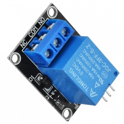
A relay is an electrically operated switch. It means that it can be turned on or off, letting the current go through or not.
Controlling a relay with the Arduino is as simple as controlling an output such as an LED.
Notice the writing on the module terminals
COM: common pin
NO (Normally Open): there is no contact between the common pin and the normally open pin. So, when you trigger the relay, it connects to the COM pin, and supply is provided to a load
NC (Normally Closed): there is contact between the common pin and the normally closed pin. There is always a connection between the COM and NC pins, even when the relay is turned off. When you trigger the relay, the circuit is opened and there is no supply provided to a load.
If you want to control a lamp, for example, it is better to use a normally open circuit, because we just want to light up the lamp occasionally.
Wiring
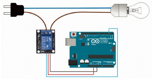
it is very straightforward as you can see. But always double-check the relay module connections before you plug things together.
GND: goes to ground
VCC: goes to 5V
IN1: controls the relay (it is connected to an Arduino digital pin)


