Using the CNC mill
1. Designing the PCB
There are several ways for designing PCB. For example you can use the following softwares:
- Fritzing (easy to use) https://fritzing.org/
- Kicad (more professional) https://www.kicad.org/
Lets start with Fritzing.
All the Fritzing Tutorials
pcb design basic tutorial
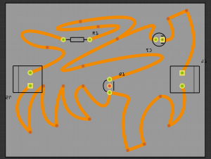
Designing a custom shape pcb
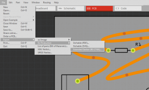
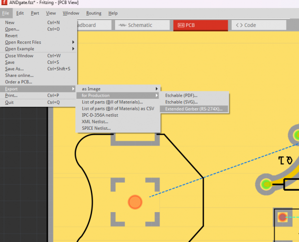
That looks already quite good. After you finished the PCBs you have to export it as a "Extender Gerber (RS-274X)"-Format! Select the folder where you would like to save it.
2. Generating the G-code
In this step you have to generate G-code with the Gerber files. G-code or sometimes called nc-code (numeric controll code) tells the CNC mill when to turn on the spindle or to which position it should move.
We will use FlatCam (http://flatcam.org/) to generate the G-Code.
- Start FlatCAM
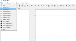
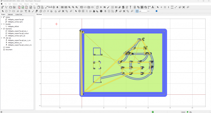
- Click on [File] -> [Open Gerber ...]
- Select the ".gbl" (copper bottom) file
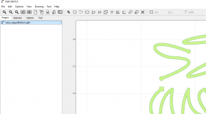
- Now select the file in the Project list and click on [selected]
settings flatcam:
- cut Z: -0.1 mm
- feedrate: 30 mm (is slow try 90)
Flatcam 8.991 Overview There is a good, concise tutorial for this Flatcam version here Flatcam single layer pcb tutorial
3. Using Mods
Alternatively we can use Mods (web based software from Fab Academy) to generate paths from .SVG or .PNG files
When using Kikad or Eagle it is relatively easy to export each layer as a .svg or .png file, when using Fritzing and having a through-hole component, we will use a slightly more bulky pipeline.
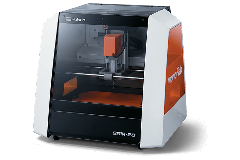
Mods project is a module based software with a web interface that already has a SRM-20 preset
Here is a good in depth tutorial how to use it but bare in mind that the interface has changed a bit and you may find differences
Here is an even longer tutorial including the finishing and soldering of a board
4. Milling the PCB
4.Trough-hole pcb with Fritzing for Mods
As mentioned, when using Kikad or Eagle it is relatively easy to export each layer as a .svg or .png file, when using Fritzing and having a through-hole component, we will use a slightly more bulky pipeline. In Fritzing it is all very straight forward if you have only surface mount components, but gets complex to export an image file with just holes.
Thus we go through a slightly more complex pipeline of two more pieces of software.
We will export gerber files from Fritzing
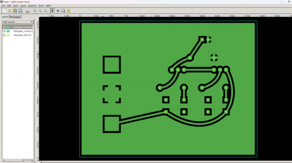
Then we will use a gerber viewing software (Gerbv [1]) or gerberlogix (https://www.easylogix.de/products_detail.php?prog_id=1) to view our
- top copper .gbl file
- our contour .gml file
- our drills .txt file
We will then export each layer we need as separate image files (.png or .svg)
And then last, before we can go to Mods we will use Gimp or Photoshop to convert images to black and white and also do some editing if we have a ground pour.
Only then, we will move to Mods.

