Using the CNC mill
1. Designing the PCB
There are several ways for designing PCB. For example you can use the following softwares:
- Fritzing (easy to use) https://fritzing.org/
- Kicad (more professional) https://www.kicad.org/
Lets start with Fritzing.
All the Fritzing Tutorials
pcb design basic tutorial
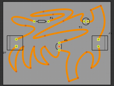
Designing a custom shape pcb
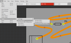
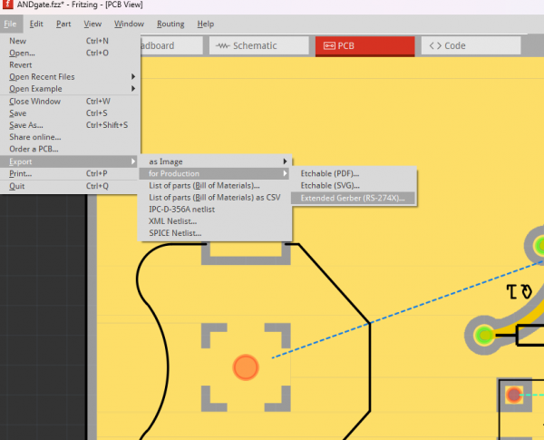
That looks already quite good. After you finished the PCBs you have to export it as a "Extender Gerber (RS-274X)"-Format! Select the folder where you would like to save it.
2. Generating the G-code
In this step you have to generate G-code with the Gerber files. G-code or sometimes called nc-code (numeric controll code) tells the CNC mill when to turn on the spindle or to which position it should move.
We will use FlatCam (http://flatcam.org/) to generate the G-Code.
The Flatcam manual
Flatcam 8.991 Overview
There is a good, concise tutorial for this Flatcam version here Flatcam single layer pcb tutorial
- Start FlatCAM
- Go to Edit -> Preferences and make sure measurements are set to millimeters.
To mill a circuit board, we will need to make three separate files, the traces, the holes and the contour.
TRACES
First for the traces:
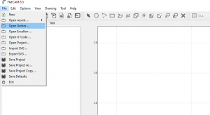
- Click on [File] -> [Open Gerber ...]
- Select the ".gbl" (copper bottom) file
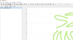
- Now select the file in the Project list and click on [selected]
- drag in "copperBottom.gbl"
- Double click on the Gerber file to go to the Selected tab.
Set the Tool Settings to:
- Tool dia: 0,3500
- #Passes : 1
- Passes overlap: 0,00000%
and Click "Generate Isolation Geometry"
Here we will set the millings settings.
Under Parameters for Tool 1
- Cut Z: -0.1100
- Uncheck Multi-Depth (default)
- Travel-Z: 2,0000 (default)
- Uncheck Tool Change (default)
- End-move Z: 50,0000
- Feedrate X-Y: 120,0000 (default)
- Feedrate Z: 60,0000 (default)
- Spindle speed: 0 (default)
Click on "Generate CNCJob object" and "Save CNC Code"
HOLES
To drill out the holes, we'll need to import your drill.txt file. Go to Files > Open > Open Excellon and navigate to your drill.txt file.
Go to Project and double click the "drill.txt" under Excellon.
The settings for the drill bit are:
- Cut Z: -2,0000
- Travel Z: 2,0000 (default)
- Uncheck Tool Change (default)
- End move Z: 50,0000
- Feedrate Z: 30,0000
Click "Create Drills GCode"
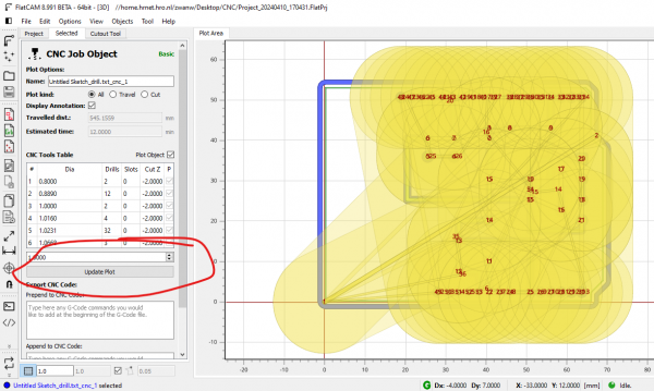
If you see huge yellow circles , lower the size to 1 if you see huge yellow circles underneath the "CNC Tools Table" and click "Update Plot".
Scroll down and click "Save CNC Code".
CONTOURS
Lastly we want to mill out the shape of the PCB.
Go to File > Open > Open Gerber and navigate to "contour.gm1"
Open the file and double click it to go to the "Selected" tab.
Select "Cutout Tool"
Object to be cutout: "contour.gm1"
Object kind: Single (default)
- Tool Diameter: 1
- Cut Z: -1,8 (default)
- Check Multi-Depth: 0,6 (default)
- Margin: 0 (default)
- Gap Size: 2
- Gaps:4 (default)
(not necessary if your circuit board is taped to the sacrificial layer properly, but if you don't mind breaking some tabs it's a safe option)
Now select "Generate Freeform Geometry"
In the Project tab, double click your new file under Geometry ending with "_cutout".
And use the following settings:
Tools Table:
1,0000 | C1
Parameters for Tool 1:
- Cut Z: -1,8 (default)
- Multi Depth: 0,6000 (default)
- Travel Z: 2,0000
- End move Z: 50,0000
- Feedrate X-Y: 120,0000
- Feedrate Z: 60,0000
- Spindle speed: 0 (default)
- Uncheck Dwell (default)
- Postprocessor: default (default)
Now select "Generate CNCJob object"
and click "Save CNC Code".
3. Milling the PCB
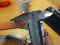
To mill a circuit board, you'll need a copper plate. Make sure you have a copper plate that is approximately 1,6-1,7mm thick and that your circuit board fits on it. The thickness can be measured using callipers.
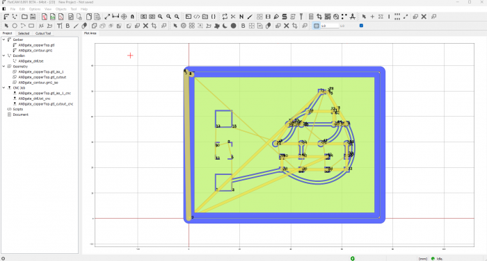
You can see the measurements of your circuit board in Flatcam by looking at the numbers on the side.
Installing your copper plate
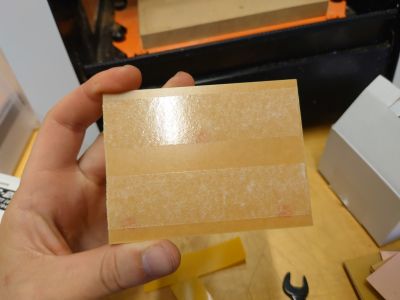
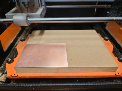
We fix your copper plate on the CNC bed by using double sided tape. Stick double sided tape on the bottom (non-copper sided) of your copper plate. Make sure you use enough tape so the PCB sticks .
Make sure it is as flat as possible!! Disturbances in height can make your traces uneven. Now stick it onto the MDF bed on the left bottom corner. Press it hard onto the MDF to make sure it sticks.
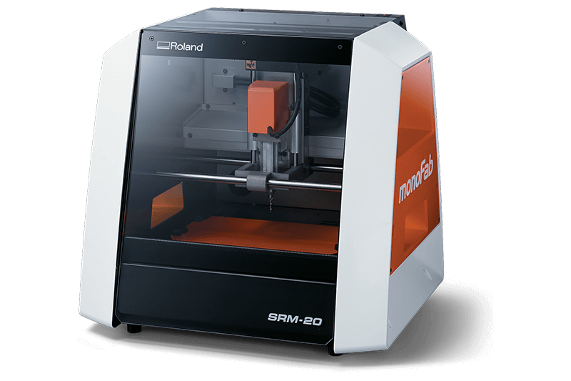
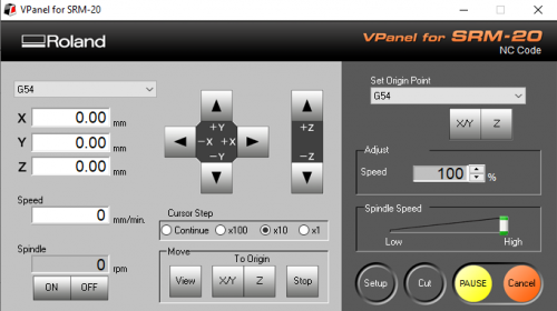
Now close the lid of the monoFab and start the software "V-Panel for SRM-20" (on desktop), make sure the mill is turned on.
TRACES
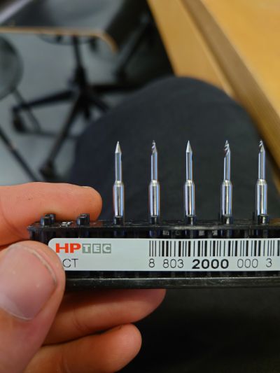
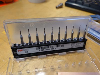
We'll start by milling out the traces. To do this, we need to make sure the V-shaped bit is installed in the CNC. The V-shaped bit can be found in the CNC box and should look like this:
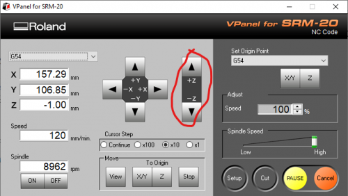
We start installing the V-shaped bit by moving the CNC-head all the way up. In V-Panel, you can do this by pressing the UP arrow with "+Z" next to it.
When the CNC head is all the way up, replace the mill unscrewing the screw holding the mill bit on the side of the CNC-head.
Now install the V-shaped bit and tighten the screw with the hex key. It should be inserted approximately this much:
You don't need to be super precise, because you will recalculate the CNC after this.
Calibrating the CNC
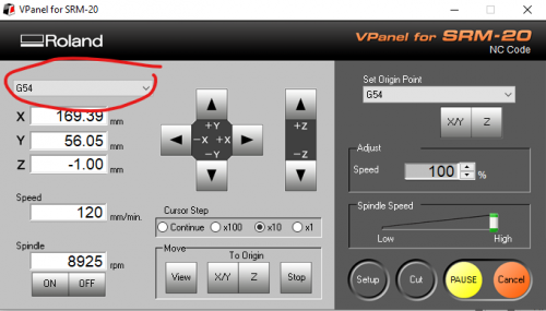
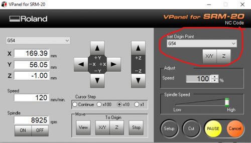
To properly mill out the traces, we need the CNC to know where the face is it needs to mill. To do this Change the Machine Coordinate System on the top left to G54:
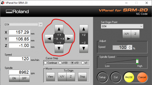
and move the Mill all the way to the bottom left corner of your copper plate using the arrows.
Now drop down the mill with the Z-arrows until almost touch the surface. !! Be careful not to hit the surface!! You will break the mill.
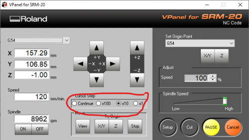
Make more precise adjustment by changing the Cursor step.
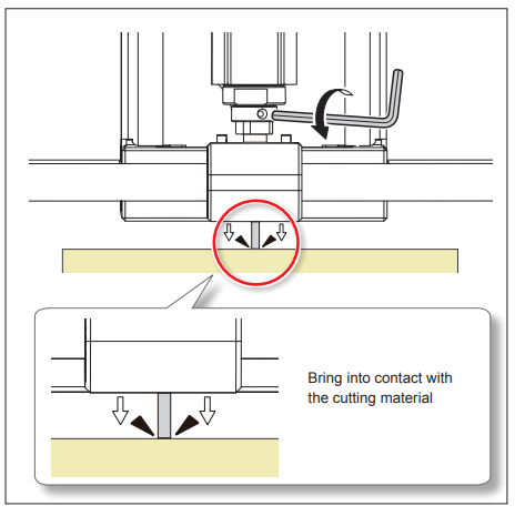
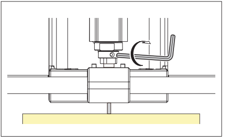
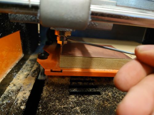
When you are as close as possible to the surface. Unscrew the mill with the small hex key, let it drop
and tighten it again.
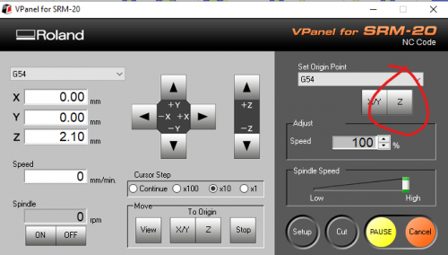
Now set the new origin point to G54 and click X/Y and Z.
X, Y, Z should now be 0, 0, 0.
Milling the Traces
When you've properly calculated the CNC for your copper plate, the mill bit should move the the bottom left corner when you press "X/Y" and "Z" under the "To Origin" tab.
If this is the case, we can start milling the traces.
Close the lid of the CNC and Press "Cut" > "Add" > and look for your "copperBottom.nc" file (or whatever you've named it).
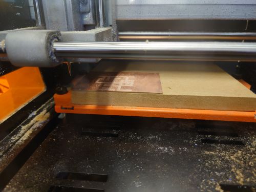
Now press "Output" and the CNC should start milling out your traces.
Testing the traces
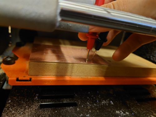
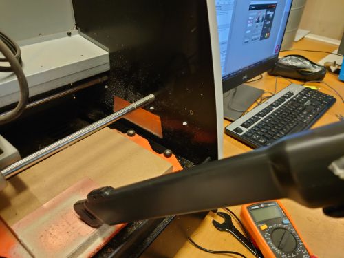
When the CNC is done, double check that the traces are deep enough. They should not make contact. Clean the copper plate with a vacuum cleaner and check it with a multimeter. Set it to continuity and check if the traces make contact with the copper plate and with each other. You will hear a beep if they do. Often, the continuity symbol on your multimeter looks like this:
Problems?
If you don't have problems with your traces, ignore this step.
Are the traces not cut deep enough? Experiment with making your traces a bit deeper by changing the Z-cut in Flatcam.
Are the traces not evenly cut? Check if you taped your copper plate properly. If you did, it might be the case that the sacrificial layer needs to be surfaces. To do this, go to:
Tutorial: Surfacing the CNC bed
HOLES
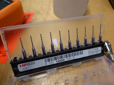
Next, we'll drill out the holes. For this we need to swap out the V-shaped bit for the drill bit. The drill bit should look like this:
The CNC should have ended it's milling with Z : 50 so it's easy to replace the V-shaped bit for the mill bit with the small hex key. If you cannot reach it, try closing the lid and moving the Mill bit around to a place where you can reach it.
When you've swapped for the drill, you need to calculate the Z-axis again, but not the X/Y . If you loose the X/Y values, you will not be able to drill the right spots on your circuit board!
Press "X/Y" under "To Origin" NOT "Z" and follow these calculation steps again:
Drop down the mill with the Z-arrows until almost touch the surface. !! Be careful not to hit the surface!! You will break the drill bit.
Make more precise adjustment by changing the Cursor step.
When you are as close as possible to the surface. Unscrew the mill with the small hex key, let it drop
and tighten it again.
Press "Z" under "New Origin Point" (NOT X/Y).
X, Y, Z should now be 0, 0, 0.
Close the lid of the CNC and Press "Cut". Select the existing files and click > "Delete" and click "Add" > and look for your "drill.nc" file (or whatever you've named it).
Now press "Output" and the CNC should start drilling out your holes.
CONTOUR
Now let's mill out the contour to give the circuit board the shape you like. To mill out the contour we'll need to use the mill bit. It looks like this:
I'll repeat the steps again for the sake of consistency.
The CNC should have ended it's milling with Z : 50 so it's easy to replace the V-shaped bit for the mill bit with the small hex key. If you cannot reach it, try closing the lid and moving the Mill bit around to a place where you can reach it.
When you've swapped for the flat mill, you need to calculate the Z-axis again, but not the X/Y . If you loose the X/Y values, you will not be able to drill the right spots on your circuit board!
Press "X/Y" under "To Origin" NOT "Z" and follow these calculation steps again:
Drop down the mill with the Z-arrows until almost touch the surface. !! Be careful not to hit the surface!! You will break the drill bit.
Make more precise adjustment by changing the Cursor step.
When you are as close as possible to the surface. Unscrew the mill with the small hex key, let it drop
and tighten it again.
Press "Z" under "New Origin Point" (NOT X/Y).
X, Y, Z should now be 0, 0, 0.
Close the lid of the CNC and Press "Cut". Select the existing files and click > "Delete" and click "Add" > and look for your "contour.nc" file (or whatever you've named it).
Now press "Output" and the CNC should start drilling out your holes.
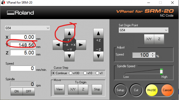
When all your milling has finished, you can take it out of the CNC. Do this by moving the bed towards you using the "+Y" arrow.
Use the vacuum cleaner to mill out all the dusty copper and epoxy (this stuff is not healthy).
Afterwards, use the spatulate to get under your pcb take take it off.
Good luck!
EXTRAAAA
4.Trough-hole pcb with Fritzing for Mods
As mentioned, when using Kikad or Eagle it is relatively easy to export each layer as a .svg or .png file, when using Fritzing and having a through-hole component, we will use a slightly more bulky pipeline. In Fritzing it is all very straight forward if you have only surface mount components, but gets complex to export an image file with just holes.
Thus we go through a slightly more complex pipeline of two more pieces of software.
We will export gerber files from Fritzing
Then we will use a gerber viewing software (Gerbv [1]) or gerberlogix (https://www.easylogix.de/products_detail.php?prog_id=1) to view our
- bottom copper .gbl file
- our contour .gml file
- our drills .txt file
We will then export each layer we need as separate image files (.png or .svg)
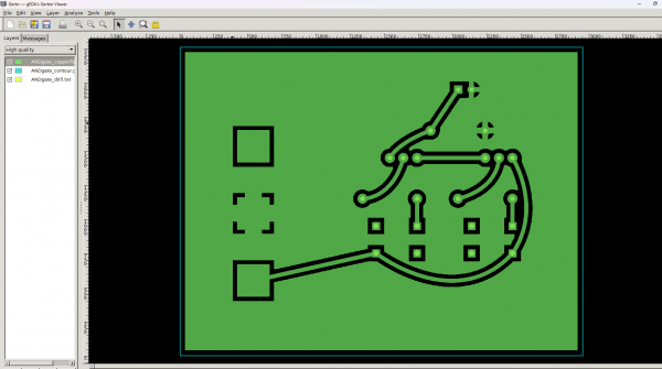
And then last, before we can go to Mods we will use Gimp or Photoshop to convert images to black and white and also do some editing if we have a ground pour.
Only then, we will move to Mods.
Tutorial: Surfacing the CNC bed
5. Panelize PCB boards
If your prototype worked properly and you want to mill a few of your PCBs in one go, you will have to use an extra software to create a panel.
One software you can use is the Gerber Panelizer. You can download the software via this website from the developer Stijn Kuipers:
https://github.com/ThisIsNotRocketScience/GerberTools/releases
First, we will make a Zip folder with the following files:
- bottom copper .gbl file
- our contour .gml file
- our drills .txt file
We then can drag and drop the zip folder into the Gerberpanelizer software that we just downloaded and installed (its located somewhere in the zip folder you just downloaded)
We can then change our panel size via panel properties in the tabs (for example the size of your copper plate), and add the zip folder as many times as you want to mill it.
After that, just click file > Export merged Gerbers . You can now create cnc files in Flatcam for your whole panel
6. Using Mods
Alternatively we can use Mods (web based software from Fab Academy) to generate paths from .SVG or .PNG files
When using Kikad or Eagle it is relatively easy to export each layer as a .svg or .png file, when using Fritzing and having a through-hole component, we will use a slightly more bulky pipeline.
Mods project is a module based software with a web interface that already has a SRM-20 preset
Here is a good in depth tutorial how to use it but bare in mind that the interface has changed a bit and you may find differences
Here is an even longer tutorial including the finishing and soldering of a board

