Arduino & Stepper motors
Stepper motor: how and why
A stepper motor is essentially a servo motor that uses a different method of motorization. Where a servo motor uses a continuous rotation DC motor and integrated controller circuit, stepper motors use multiple toothed electromagnets arranged around a central gear to define position.
Stepper motors require an external control circuit or micro controller (for instance a Raspberry Pi or Arduino) to individually energize each electromagnet and make the motor shaft turn. When electromagnet ‘A’ is powered it attracts the gear’s teeth and aligns them, slightly offset from the next electromagnet ‘B’. When ‘A’ is switch off, and ‘B’ switched on, the gear rotates slightly to align with ‘B’, and so on around the circle, with each electromagnet around the gear energizing and de-energizing in turn to create rotation. Each rotation from one electromagnet to the next is called a "step", and thus the motor can be turned by precise predefined step angles through a full 360 Degree rotation.
Stepper motors are available in two varieties; unipolar or bipolar. Bipolar motors are the strongest type of stepper motor and usually have four or eight leads. They have two sets of electromagnetic coils internally, and stepping is achieved by changing the direction of current within those coils. Unipolar motors, identifiable by having 5,6 or even 8 wires, also have two coils, but each one has a center tap. Unipolar motors can step without having to reverse the direction of current in the coils, making the electronics simpler. However, because the center tap is used to energize only half of each coil at a time they typically have less torque than bipolar.
These motors have four to eight wires you need to use to control the pulses to make the shaft step continuously, so they’re more complicated to control than the previously described motors. They are squatter looking than the rest of the DC motor family, and have less torque than you might expect for their size and weight. However, they’re also the fastest way to integrate both speed and position control into a project.
The design of the stepper motor provides a constant holding torque without the need for the motor to be powered and, provided that the motor is used within its limits, positioning errors don't occur, since stepper motors have physically predefined stations.
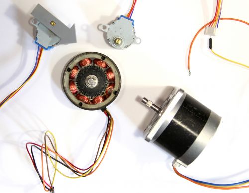
Steppers work by moving in a bunch of little increments, or steps. If you step them fast enough, it looks like continuous motion. Each time one of the coils is energized, it pulls one of the teeth on the shaft toward it to complete one step. For example, a 200-step motor moves in a full 360° circle at 1.8° per step.
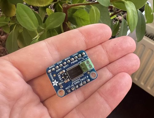
With a TB6612 Motor Driver
This driver can drive 1 stepper motor or two DC Motors
Update 11.10.24: More reliable than the Adadruit Motor Shield
Here is an overview of this driver :)
Components
- Arduino board (we are using the Uno in this example)
- TB6612 Motor Driver
- Breadboard
- Jumper Wires
- External Power Supply
The amount of power depends on the specifcs of your motor. At the station we have switching power supplies for this purpose.
Wiring
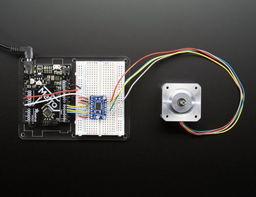
- Place your motor driver on the breadboard
- Connect the Pins of the Motor Driver to the ones on the Arduino:
-->VM to Vin Pin
-->Vcc to 5V
-->GND to ground
-->AIN2 to Digital 4
-->AIN1 to Digital 5
-->BIN1 to Digital 6
-->BIN2 to Digital 7
-->PWMA and PWMB to 5V
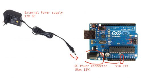
In this case we are powering the motor with the Vin Pin of the Arduino. The pin is connected to the DC connector. You can supply the eternal 12 volt power here form your power supply. This will be used to power the Arduino as well. Alternatively, you can connect your external power supply to the green screw terminals on the Motor Driver. They have a + and - connection that can go directly to your power supply.
- Connect the Motor to the Motor Driver
Your stepper motor, accordingly to the type, will most likely have 4 wires. Some of them can also have 5 or 6. On the motor driver you see that you have 2 pin conenctions for Motor A and two for Motor B. To figure out which one of the wires of the motor goes where you need to understand which one of the pair of wires is coil A and coil B of the motor.
If you don't know you can check this with a multimeter. Follow this video to see how. If you are working with a stepper motor with more than 4 wires you will see that it will have still two pair of wires that are the two coils. The extra wire(s) can be ignored.
Here's a scheme of common wire connections id you don't have a multimeter to check the coils.
You have now determined the two pairs of wire to connect to the motor driver. Each pair will be connected to the Motor A and Motor B pins on the driver.
-->Motor A to one of the coils
-->Motor B to the other coil
Coding
- Open the Arduino IDE on your computer
- Make sure your board is connected and the right port is selected
- Upload the code
For this basic test we are using the in build Arduino Stepper library.
#include <Stepper.h>

// change this to the number of steps on your motor
#define STEPS 200

// create an instance of the stepper class, specifying
// the number of steps of the motor and the pins it's
// attached to
Stepper stepper(STEPS, 4, 5, 6, 7);


void setup()
{
  Serial.begin(9600);
  Serial.println("Stepper test!");
  // set the speed of the motor to 30 RPMs
  stepper.setSpeed(60);
}

void loop()
{
  Serial.println("Forward");
  stepper.step(STEPS);
  Serial.println("Backward");
  stepper.step(-STEPS);
}
With a Adafruit Motor Shield
This driver can drive up to 2 stepper motors or 4 DC motors
Update 11.10.24: The ones we have at the station are a bit old and not super reliable
Components
Now you might want to connect the stepper motor to a microcontroller like Arduino.
You will need:
- Arduino Uno
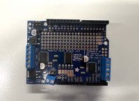
- Adafruit Motor Shield
- Jumper wires
- External power supply
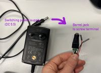
Your Arduino can only provide 5 volt while the motor usually requires between 9 and 12 volt so we are adding an external power supply.
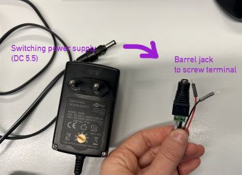
You can supply energy in other ways as well, like for instance with a battery. In our case we are using a switching power supply connected to a barrel jack to screw terminal with two jumper wires.
Wiring
1. Place the Motor shield on the top of your Arduino
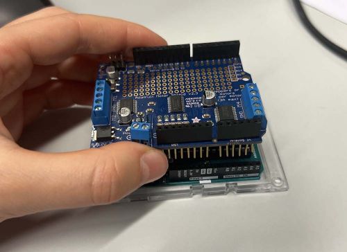
You can see that your shield has 3 blue screw terminals on top, 2 for your motors and one for your power supply. The other pins of the Arduino are still free in case you want to add sensors or other parts to your project.
2. Connect the motor to one of the two main screw terminal blocks
There are several types of stepper motors and they can have different numbers of wires of different colors making it a bit hard sometimes to understand how to properly connect it to your circuit without having to use a multimeter.
Here is a diagram of the wires color combinations and how they should be connected to the motor shield.

The final result should look like this:
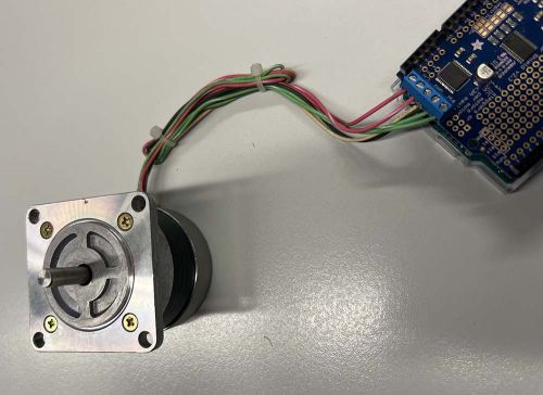
3.Connect the Motor Shield to the power supply
Connect the power supply wires to the power screw terminal on your shield. There is a + and - sign on the shield to help you. If you wired it correctly an LED light on the shield should turn on. If not, check if your power supply is actually working.
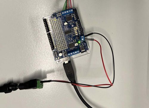
4.Connect the Arduino to your computer
Coding
1. Open the Arduino IDE on your computer
If you don't have the software you can download it from here: https://www.arduino.cc/en/software
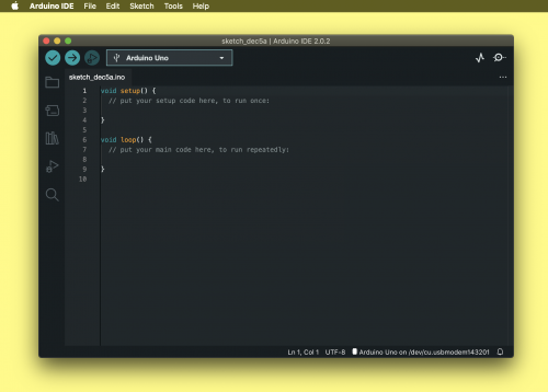
2. Install the Motor Shield library
Arduino often requires libraries to be able to communicate to different types of hardware, like for instance our shield.
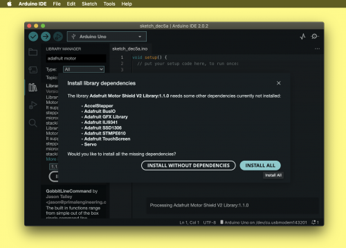
Install the Adafruit Motor Shield Library by going on Sketch > Include Library > Manage Libraries. A search bar will appear where you can look for it. In this example we are using the Adafruit Motor Shield V2 Library because that's our shield model.
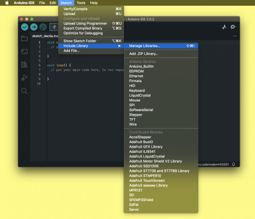
Install it with all its dependencies.
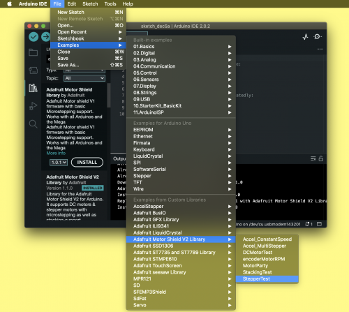
3. Test your motor with the Library example code
Now that you installed the library you can use one of the example codes that come with it to test if your motor is working and wired correctly.
Go to File > Examples > Adafruit Motor Shield V2 Library > Stepper test .
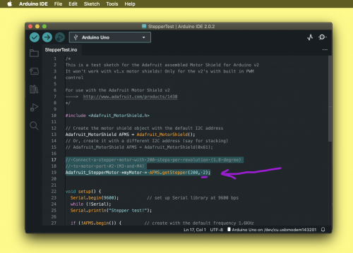
At line 19 of your code you can check if you are using the same motor port. Write 1 if you have your motor connected to the M1 M2 port of your shield or 2 if you are using the M3 M4.
Before uploading the code make sure that you have the right board ad port selected. You can check this by going to Tools.
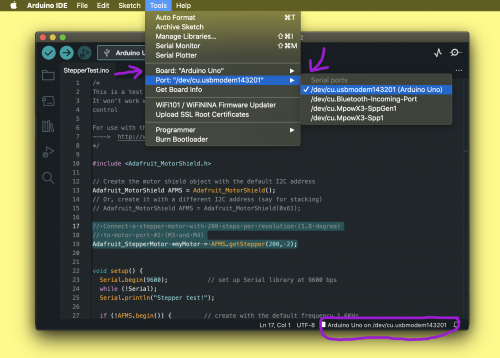
Now upload the code on your board by pressing the →.
4. Customize your code
Your motor should now be making 4 different kinds on motions accordingly to the example code.
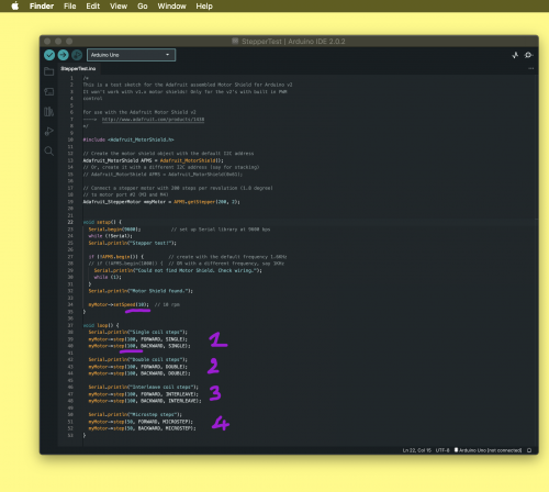
You can now modify it, accordingly to what you want to achieve by determining the speed, number of steps and direction. Remember that unlike Servo motors the value determining the amount of rotation is not in degrees° but in steps. A full 360 Degree rotation corresponds to 200 steps.
With the CNC Shield and DRV8825 Drivers
This set up you can drive up to 4 stepper motors
This solution is mostly used for CNC machines and 3D printer but it can be used also in other cases as it can allow to driver up to 4 steppers.
Here's a guide on how to set this up
Components
* Arduino Uno (in this case we cannot use another board as the shield in made to be stacked on it)
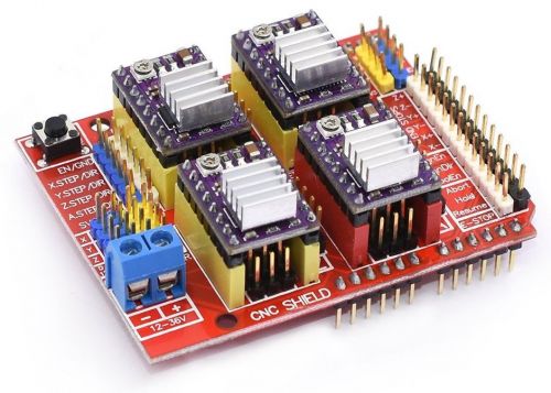
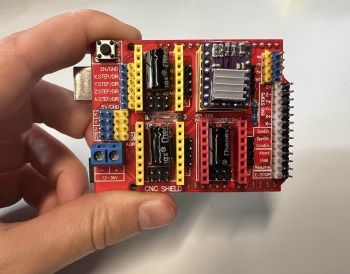
* CNC Shield
* DRV8825 Motor Driver - one for each stepper you are going to use, in this example we use one
* External Power supply
* Barrel jack connector
* Stepper motor(s) - we will use one in this example
Wiring
-->Mount CNC shield onto Arduino Uno
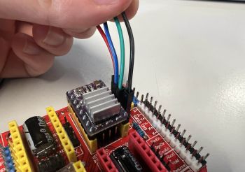
-->Mount the DRV8825 in one of the 4 slots available making sure you are doing it in the right direction
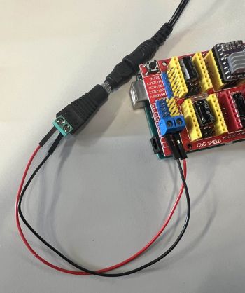
-->Connect your power supply to the barrel jack adaptor
-->Connect the power supply wires to the power screw terminal on the shield
-->Connect the motor to the pins on right side of the DRV8825
Coding
- Open the Arduino IDE on your computer
- Make sure your board is connected and the right port is selected
- Upload the code
This code work with stepper Y (the one we connected). You can easily add the other ones (stepX,stepZ are already declared in the code)
// defines pins numbers

const int stepX = 2;
const int dirX  = 5;
const int stepY = 3;
const int dirY  = 6;
const int stepZ = 4;
const int dirZ  = 7;
const int enPin = 8;


void setup() {

  // Sets the two pins as Outputs

  pinMode(stepX,OUTPUT);
  pinMode(dirX,OUTPUT);
  pinMode(stepY,OUTPUT);
  pinMode(dirY,OUTPUT);
  pinMode(stepZ,OUTPUT);
  pinMode(dirZ,OUTPUT);
  pinMode(enPin,OUTPUT);

  digitalWrite(enPin,LOW);
  digitalWrite(dirX,HIGH);
  digitalWrite(dirY,LOW);
  digitalWrite(dirZ,HIGH);
}

void loop() {
  //how many steps is taking (200 is a full turn)
  for(int x = 0; x < 200; x++) {
    digitalWrite(stepY,HIGH);
    //speed of the steps
    delayMicroseconds(1000);
    digitalWrite(stepY,LOW);
    delayMicroseconds(1000);
  }

  delay(1000);
  //change spinning direction
  digitalWrite(dirY,HIGH);

  for(int x = 0; x < 200; x++) {
    digitalWrite(stepY,HIGH);
    delayMicroseconds(1000);
    digitalWrite(stepY,LOW);
    delayMicroseconds(1000);
  }

  delay(1000);
  digitalWrite(dirY,LOW);

}
