Case Study 01: Magnetic Dreams / The Walkman
The digital realm is an avant-garde to the extent that it is driven by perpetual innovation and perpetual destruction. The built-in obsolescence of digital culture, the endless trashing of last year’s model, the spendthrift throwing away of batteries and mobile phones and monitors and mice . . . and all the heavy metals, all the toxins, sent off to some god-forsaken Chinese recycling village . . . that is the digital avant-garde.
Sean Cubitt interviewed by Simon Mills, Framed, online at <www.framejournal.net/interview/10/ sean-cubitt>
Magnetic Tape as Rebel media
Magnetic tape allowed for music/sound content to be recorded by anyone.
It spurred the creation and distribution of 'amateur' content, that could range from entertainment, trough art, to disruption.
The cassette tape made it even more accessible to distribute content and be able to bypass censorship. It could slip unseen, handed under tables, recorded and copied at home, exchanged in back streets, recopied and distributed again.
Magnetic tape
Magnetic tape is a medium for magnetic recording, made of a thin, magnetizable coating on a long, narrow strip of plastic film. It was developed in Germany in 1928, based on magnetic wire recording. Devices that record and play back audio and video using magnetic tape are tape recorders and video tape recorders respectively. A device that stores computer data on magnetic tape is known as a tape drive. And currently very interesting to know about LTFS by IBM used in cloud services today
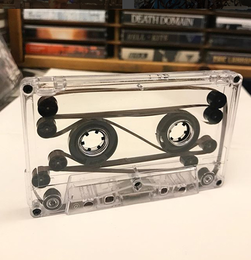
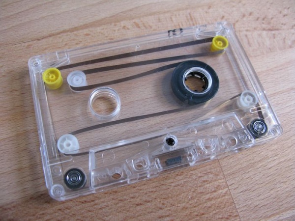
The audio cassette
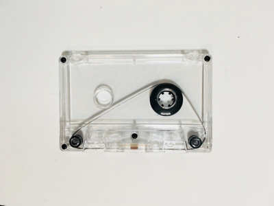
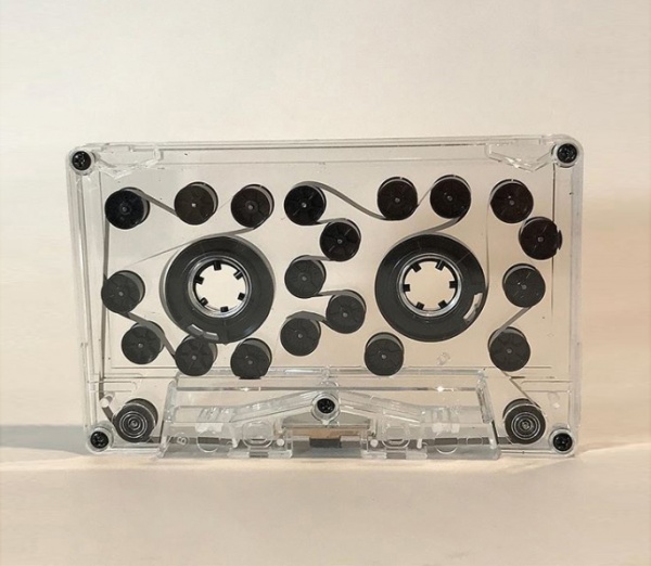
The compact cassette (aka. cassette tape) was originally developed and released by Philips in 1962 in Hasselt, Belgium as an attempt to develop a new standard in audio storage. This replaced reel-to-reel recorders that were more complex and expensive to use. The cassette tape, allowed anyone to make recordings without the technical skills that were needed for the reel-to-reel.
The cassette tape peaked in popularity by the late 1980s, where the market had drastically dropped in both Europe and North America. This was due to a new technology called compact discs (CDs for short) that became popular in the 1990s. By 2001, cassettes had pretty much dropped out for the race as its market share was less than 5%. The following year, U.S music companies had stopped producing them. Blank cassette tapes are still being made and sold today and after a decade of no music being released by big music companies on cassette tape, there has been a comeback, including names such as Justing Bieber releasing on cassette tape.
“It’s the tangibility of having this collectible format and a way to play music that isn’t just a stream or download,” says techno DJ Phin, who has just released her first EP on cassette as label boss of Theory of Yesterday. “I find them much more attractive than CDs. Tapes have a lifespan, and unlike digital music, there is decay and death. It’s like a living thing and that appeals to me.” Phin left the bulk of her own 100-strong cassette collection in Turkey, carefully stored at her parents’ home, but bought “20 or 25 really special ones” when she moved to London. “I’m from that generation,” she says. “It’s a nostalgia thing – I like the hiss.”
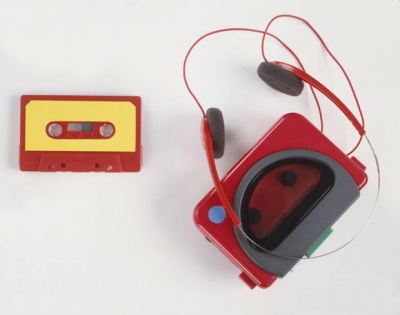
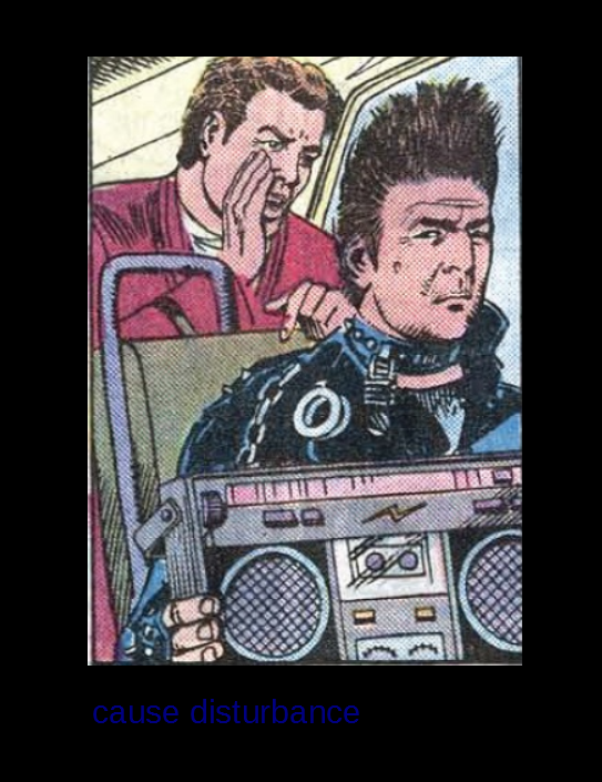
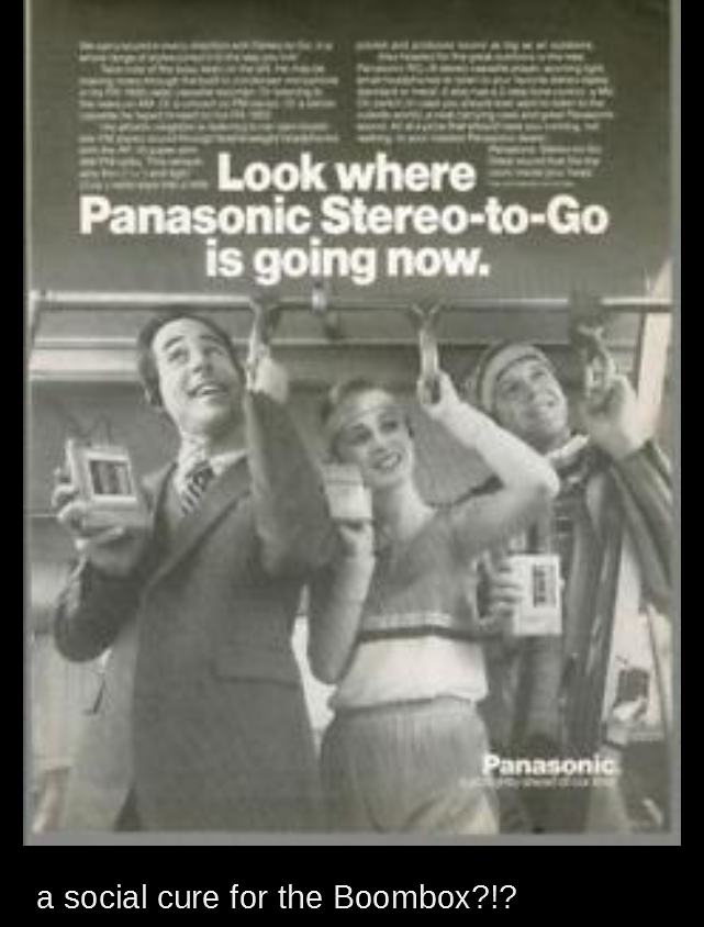
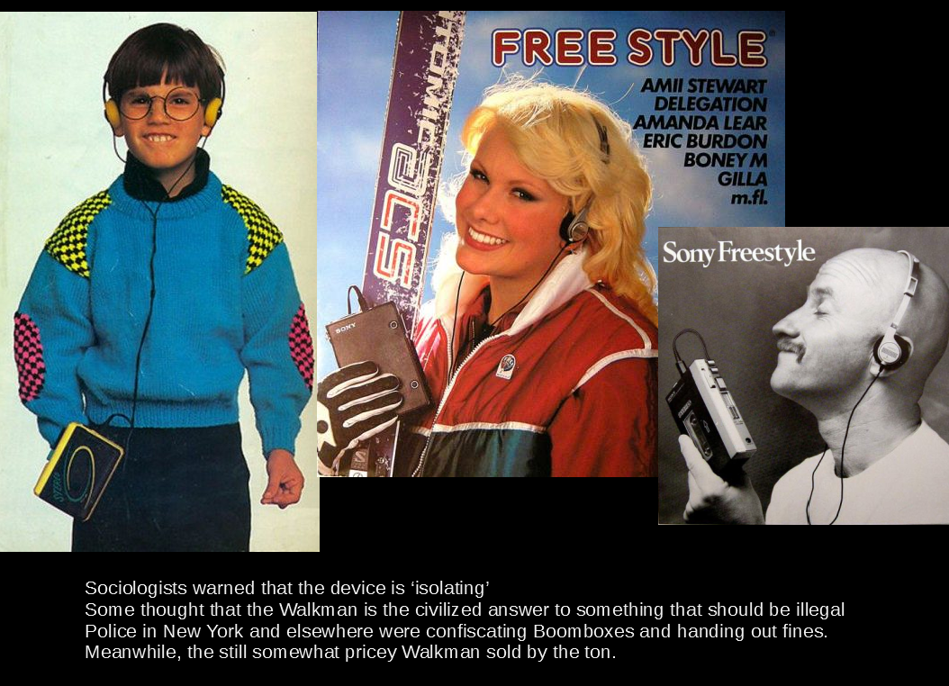
The walkman and the end of the boombox
From the boombox to the walkman, to the ipod, to the iphone
and now to reissued nostalgia [[1]]
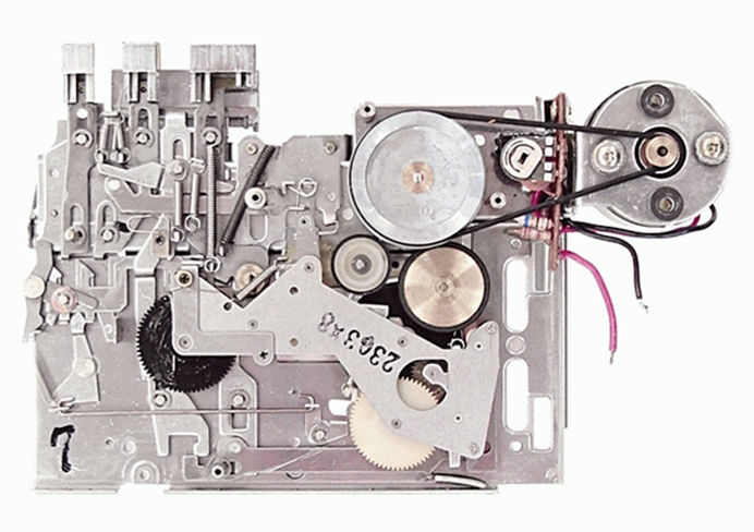
Anatomy of the Walkman
Modding
Part One: manual control
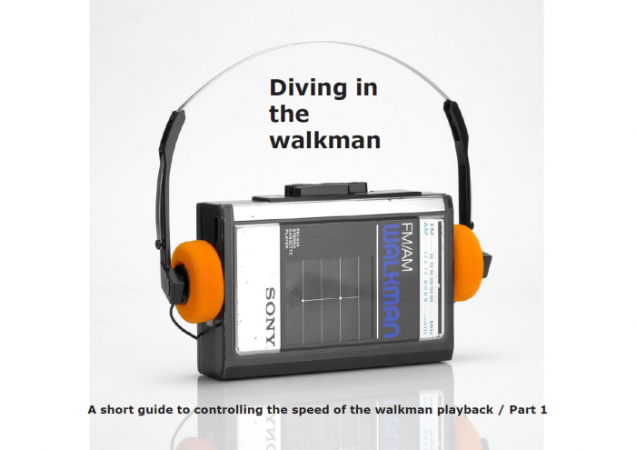
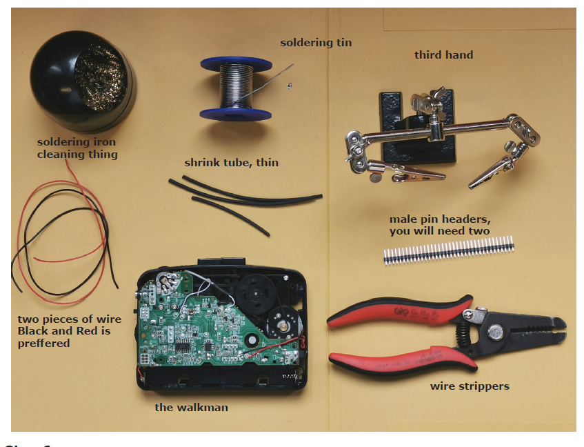
Here find the STEP BY STEP TUTORIAL Part 01 Media:WalkmanTutorial.pdf
Here find the STEP BY STEP TUTORIAL Part 01 Media:WalkmanTutorial.pdf
Part two: sensor input control
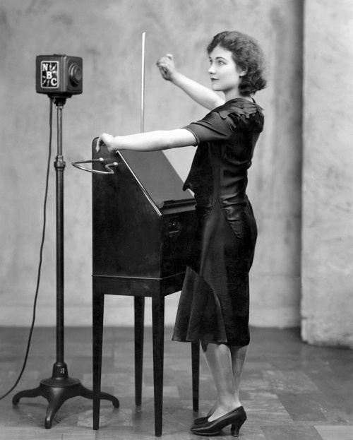
The Theremin Walkman
READ about this great media object
analog read LDR
This is an example from the Arduino examples.
/*
  AnalogReadSerial

  Reads an analog input on pin 0, prints the result to the Serial Monitor.
  Graphical representation is available using Serial Plotter (Tools > Serial Plotter menu).
  Attach the center pin of a potentiometer to pin A0, and the outside pins to +5V and ground.

  This example code is in the public domain.

  http://www.arduino.cc/en/Tutorial/AnalogReadSerial
*/

// the setup routine runs once when you press reset:
void setup() {
  // initialize serial communication at 9600 bits per second:
  Serial.begin(9600);
}

// the loop routine runs over and over again forever:
void loop() {
  // read the input on analog pin 0:
  int sensorValue = analogRead(A0);
  // print out the value you read:
  Serial.println(sensorValue);
  delay(1);        // delay in between reads for stability
}
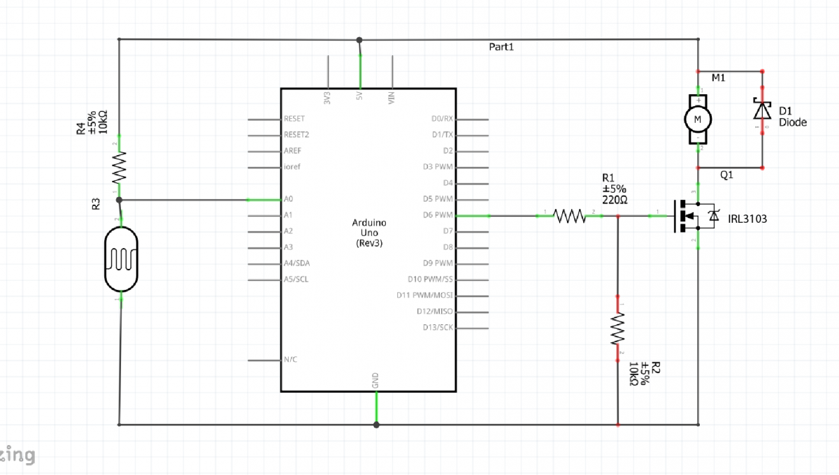
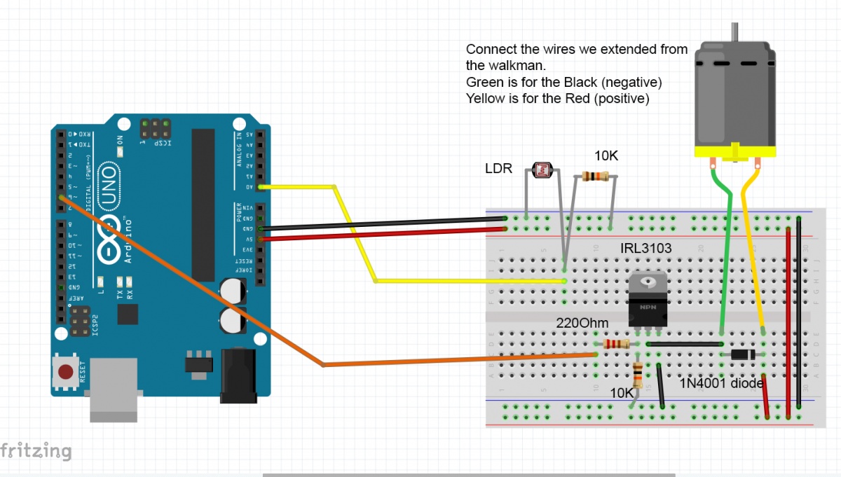
Now control the motor
#include <PWMFreak.h> //install this library

int motorPin = 6;       //pin that the walkman motor is attached to
int sensorPin = A0;    // pin that the sensor is attached to
int sensorValue = 0;         // the sensor value
int sensorMapped = 0;         // the sensor value after mapping
int sensorConstrained = 0;    //the sensor value constrained

void setup() {
  pinMode(motorPin, OUTPUT);
  setPwmFrequency(6, 1); //set PWM frequency for pin 6 to 62500.00 Hz
  //TCCR0B = TCCR0B & B11111000 | B00000001; //that is another way to set the D5 & D6 frequency, without using the library
  Serial.begin(9600);
}

void loop() {
  // read the sensor:
  sensorValue = analogRead(sensorPin);
  Serial.println(sensorValue);

  // apply the calibration to the sensor reading and map it
  sensorMapped = map(sensorValue, 750, 995, 90, 200);

  // in case the sensor value is outside the range seen during calibration
  sensorConstrained = constrain(sensorMapped, 90, 200);

  analogWrite(motorPin, sensorConstrained);
}
Add a calibration routine
#include <PWMFreak.h> //install this library

int motorPin = 6;       //pin that the walkman motor is attached to
int sensorPin = A0;    // pin that the sensor is attached to
int sensorValue = 0;         // the sensor value
int sensorMin = 1023;        // minimum sensor value
int sensorMax = 0;           // maximum sensor value

void setup() {
  pinMode(motorPin, OUTPUT);
  pinMode(13, OUTPUT); //set pin 13 as an output
  digitalWrite(13, HIGH);  //turn on the on-board led to indicate calibration period
  // calibrate during the first five seconds
  while (millis() < 5000) {
    sensorValue = analogRead(sensorPin);

    // record the maximum sensor value
    if (sensorValue > sensorMax) {
      sensorMax = sensorValue;
    }

    // record the minimum sensor value
    if (sensorValue < sensorMin) {
      sensorMin = sensorValue;
    }
  }

  // signal the end of the calibration period
  digitalWrite(13, LOW);

  setPwmFrequency(6, 1); //set PWM frequency for pin 6 to 62500.00 Hz
  //TCCR0B = TCCR0B & B11111000 | B00000001; //that is another way to set the D5 & D6 frequency, without using the library
  Serial.begin(9600);
}

void loop() {
  // read the sensor:
  sensorValue = analogRead(sensorPin);

  // apply the calibration to the sensor reading and map it
  sensorValue = map(sensorValue, sensorMin, sensorMax, 90, 200);

  // in case the sensor value is outside the range seen during calibration
  sensorValue = constrain(sensorValue, 90, 200);

  Serial.println(sensorValue);
  analogWrite(motorPin, sensorValue);
}
