Flora-basic
Microcontrollers
Computer and processor are generic terms for anything that can run a program, basically.
A controller or microcontroller usually refers to a simple processor that does only one task, like listening to sensors.
In explaining microcontrollers, we’ll distinguish them from computers, which contain more powerful processors that can run an operating system.
Arduino
what is an Arduino?
Arduino is an open source physical computing platform based on a simple input/output (I/O) board and a development environment that implements the Processing language. Arduino can be used to develop standalone interactive objects
or can be connected to software on your computer.
Arduino is composed of two major parts: the Arduino board, which is the piece of hardware you work on when you build your objects;
and the Arduino IDE, the piece of software you run on your computer. You use the IDE to createa sketch (a little computer program)
that you upload to the Arduino board. The sketch tells the board what to do.
In the meantime, HERE you can find ANYTHING about Arduino, including download the software
find a detailed introduction here [[1]]
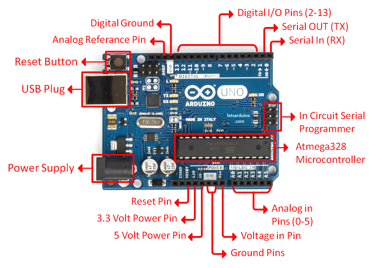
The pins on your Arduino are the places where you connect wires to construct a circuit (probably in conjunction with a breadboard and some wire. They usually have black plastic ‘headers’ that allow you to just plug a wire right into the board. The Arduino has several different kinds of pins, each of which is labeled on the board and used for different functions.
First things first, Blink it
we start by figuring put if our Arduino is all good or it is somehow damaged ...it is a basic test to check and run a simple script at the same time.
Go to File ---> Examples ---> Basics --->Blink
so we have something like this
/*
  Blink
  Turns on an LED on for one second, then off for one second, repeatedly.

  Most Arduinos have an on-board LED you can control. On the Uno and
  Leonardo, it is attached to digital pin 13. If you're unsure what
  pin the on-board LED is connected to on your Arduino model, check
  the documentation at http://www.arduino.cc

  This example code is in the public domain.

  modified 8 May 2014
  by Scott Fitzgerald
 */


// the setup function runs once when you press reset or power the board
void setup() {
  // initialize digital pin 13 as an output.
  pinMode(13, OUTPUT);
}

// the loop function runs over and over again forever
void loop() {
  digitalWrite(13, HIGH);   // turn the LED on (HIGH is the voltage level)
  delay(1000);              // wait for a second
  digitalWrite(13, LOW);    // turn the LED off by making the voltage LOW
  delay(1000);              // wait for a second
}
GOOOD! lets dissect this
- commenting / one line and multiple lines
- setup
- loop
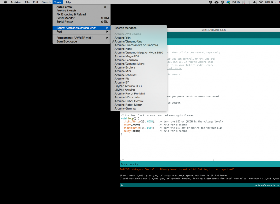
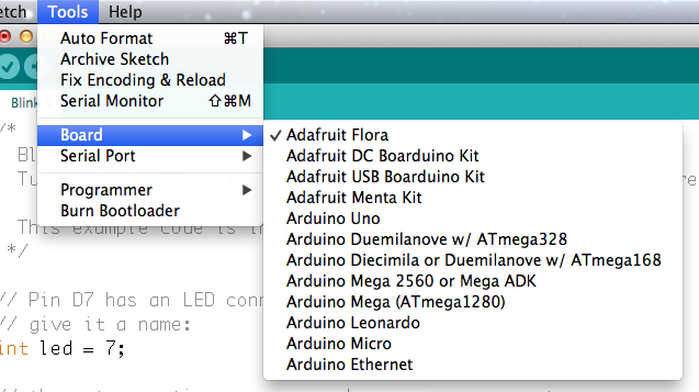
Choose board
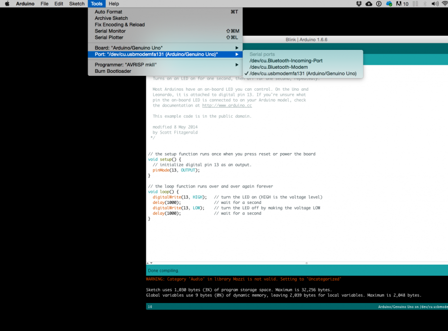
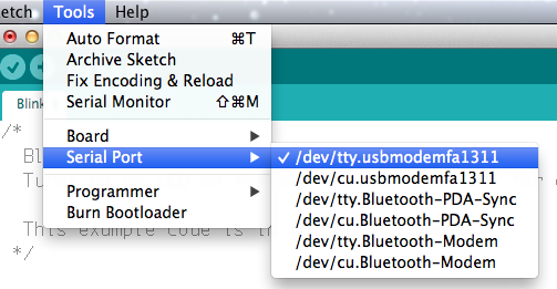
Choose port
Lets compile this
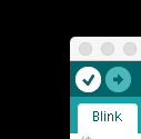
--- Press/ Click upper most left button, looks like a Tick. Observe the messages appearing in the bottom of the Arduino software window ( there must be a sentence Done Compiling
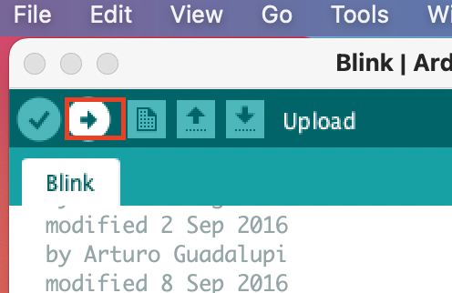
Lets upload this
And we should have a Blinking aka Flashing on board LED
Adafruit Flora
How's that different?
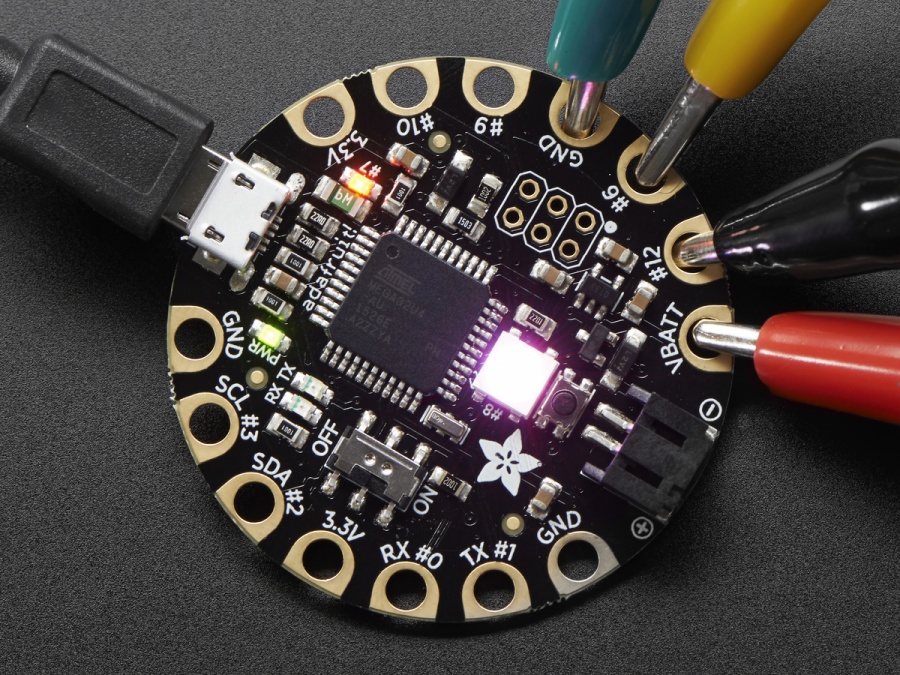
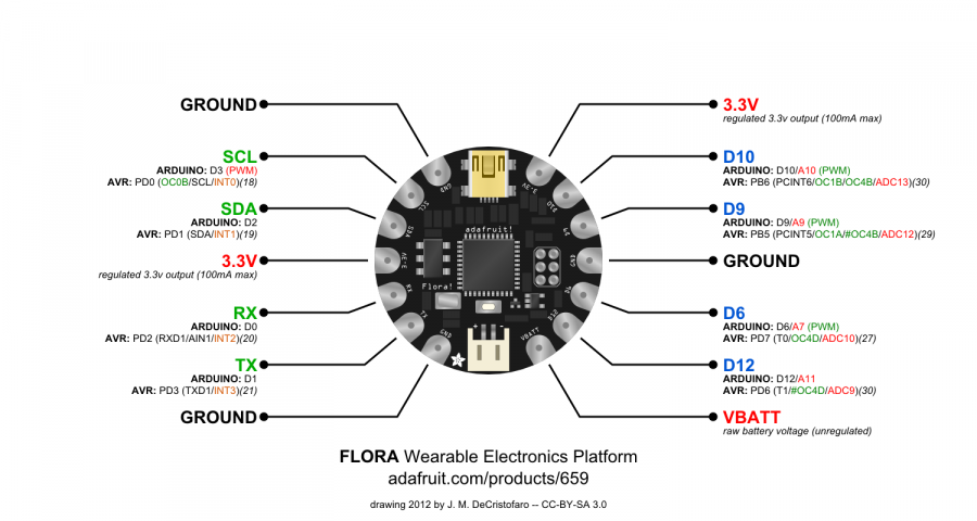
The Flora, produced by adafruit, is a microcontroller, just like the Arduino Uno, but designed for wearable projects. Thus, is a little different from the normal boards from the hardware side, since the pins go out to those big wide sewable pads, instead of normal pin headers (like on the Uno)
Before we start we all have to do this click click
Overview
Blink that one now
// Pin D7 has an LED connected on FLORA.
// give it a name:
int led = 7;

// the setup routine runs once when you press reset:
void setup() {
  // initialize the digital pin as an output.
  pinMode(led, OUTPUT);
}

// the loop routine runs over and over again forever:
void loop() {
  digitalWrite(led, HIGH);   // turn the LED on (HIGH is the voltage level)
  delay(1000);               // wait for a second
  digitalWrite(led, LOW);    // turn the LED off by making the voltage LOW
  delay(1000);               // wait for a second
}
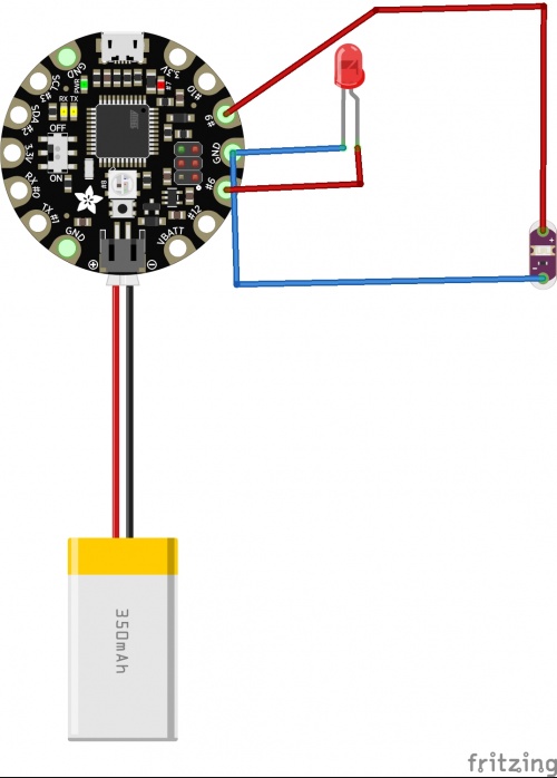
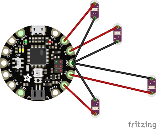
Exercise: Wiring Additional LEDs
if you change the Arduino code above from pin D7 to pin D9. you can bink an external LED.
Now, try to write an Arduino code to program additional LEDs with different blinking intervals.
Get some data
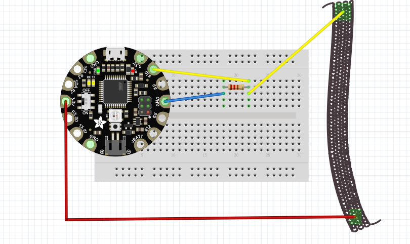
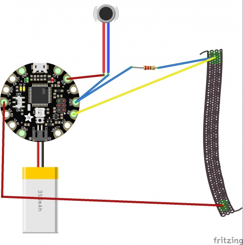
now let's read some data from sensors and Flora
We will wire things up like that:
// any function will see this variable
const int sensor= A10;

// the setup routine runs once when you press reset:
void setup() {
  pinMode(sensor, INPUT);
  // initialize serial communication at 9600 bits per second:
  Serial.begin(9600);
}

// the loop routine runs over and over again forever:
void loop() {
  // read the input on analog pin 0:
  int sensorValue = analogRead(sensor);
  Serial.println(sensorValue);
}
Work with the data
Our motor will like values from 0 to 180 But we receive other values, so how about using the Map function
const int sensor= A10;
int mappedVal=0;


// the setup routine runs once when you press reset:
void setup() {
  pinMode(sensor, INPUT);
  // initialize serial communication at 9600 bits per second:
  Serial.begin(9600);
}

// the loop routine runs over and over again forever:
void loop() {
  // read the input on analog pin 0:
  int sensorValue = analogRead(sensor);
  mappedVal = map(sensorValue, 9, 44, 0, 180);
  Serial.println(mappedVal);
}
Still, not happy enough. We want to make sure that before we add our motor, the values do not exceed og go below the range 0-180 So let's Constrain
const int sensor= A10;
int mappedVal=0;
int constrainedVal = 0;


// the setup routine runs once when you press reset:
void setup() {
  pinMode(sensor, INPUT);
  // initialize serial communication at 9600 bits per second:
  Serial.begin(9600);
}

// the loop routine runs over and over again forever:
void loop() {
  // read the input on analog pin 0:
  int sensorValue = analogRead(sensor);
  mappedVal = map(sensorValue, 9, 44, 0, 180);
  constrainedVal = constrain(mappedVal, 10, 150);
  Serial.println(constrainedVal);
}
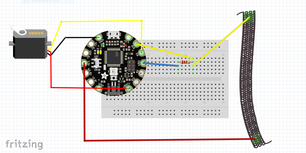
And finally, lets add the motor
const int sensor= A10;
const int motor = 9;
int motorval = 0;
int constrainedVal = 0;


// the setup routine runs once when you press reset:
void setup() {
  pinMode(sensor, INPUT);
  pinMode(motor, OUTPUT);
  // initialize serial communication at 9600 bits per second:
  Serial.begin(9600);
}

// the loop routine runs over and over again forever:
void loop() {
  // read the input on analog pin 0:
  int sensorValue = analogRead(sensor);
  motorval = map(sensorValue, 9, 44, 0, 180);
  constrainedVal = constrain(motorval, 10, 150);
  analogWrite( motor, constrainedVal);
  delay(1);        // delay in between reads for stability
  // print out the value you read:
  Serial.println(constrainedVal);
}
Addtional Exercise
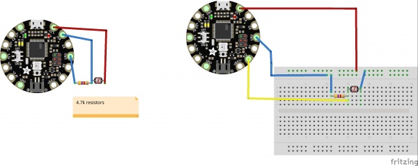
1. Read the analog value of the Photoresistor:
you can reference on Arduino Built-In Examples: [|AnalogReadSerial]
note: don't forget to change the input pin number.
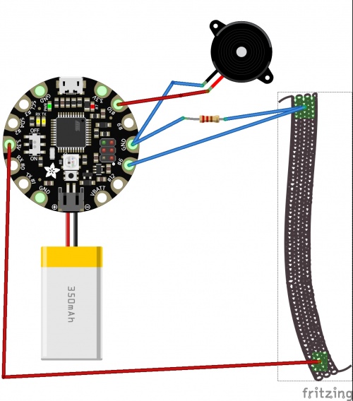
2. use the stretch sensor value to turn on the vibration motor.
Look Arduino Built-In Examples: [|Analog In, Out Serial]
or use the if statement: [|check here]
for example: if the sensor value is bigger then a certain value, the motor will start to vibrate.
3.use a stretch sensor to generate tones and pitch.
Look Arduino Built-In Examples: [|tonePitchFollower]
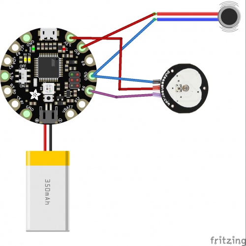
4.vibrate on heartbeats
and open example GettingStartedProject
change the
int PulseSensorPurplePin = 0;
into
int PulseSensorPurplePin = A7;
and
int LED13 = 13;
into
int LED13 = 10;
and wire the sensor and motor according to the diagram below.
upload your code and it will work!
