Trans/humanism-TransformationDesign-2021
Planning
Week 1: 05.02 Introduction, context and ice breaking!
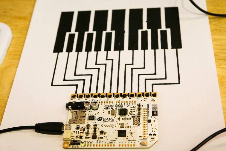
Week 2: 12.02 all those platforms and what to expect? Getting started with the Bare touch boards
Week 3: 17.02 Circuit Playground: when its all on one board!
Week 4: 03.03 Arduino: same, same but different
Week 5: 17.03 Mode: Advanced. Sensors and Arduino
Week 6: 24.03 Mode: even more advanced. More than one thing, timing and Arduino.
Week 7: 31.03 A day before the presentation, I will be available for some last min help:)
week 1:
Some context
Re-imagining the exiting

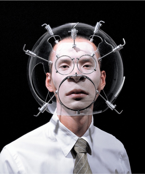
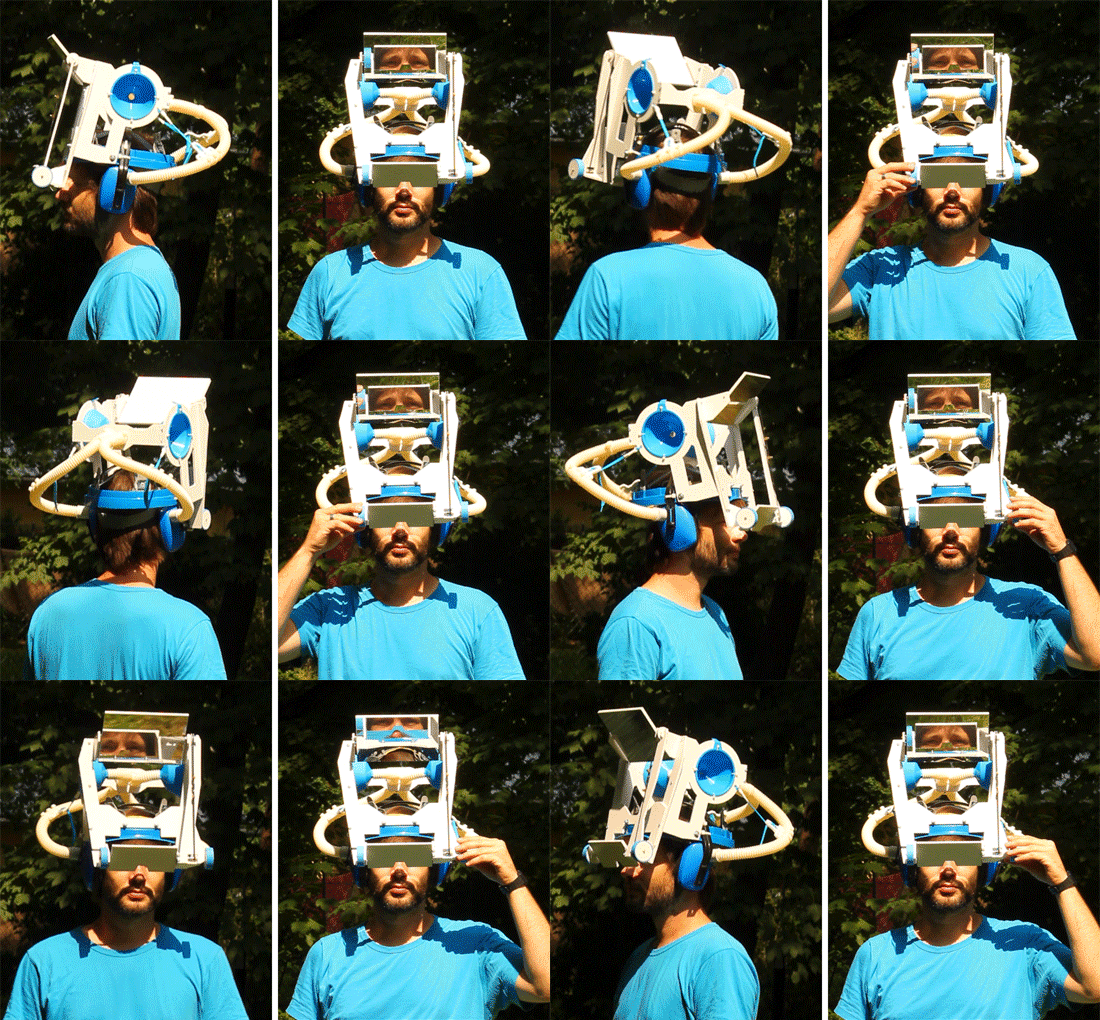
Hyungkoo Lee, Altering features
The helmet-like wearable sculptures, merge the worlds of sociology and biology into a strange and unnerving mix. Lee’s ‘helmet’ contains spaces for interchangeable lenses which can alternately emphasize or minimize various facial features. The lenses can produce disturbingly exaggerated facial expressions, faces that are cartoonishly demure or aggressive. Lee’s series underscores the body’s important role in social life and everyday flows of power.
Engineered to optically exaggerate facial and bodily features, the series was initiated in an attempt to overcome the “undersized Asian male complex” the artist claims he suffered from while completing his MFA at Yale.
LINK
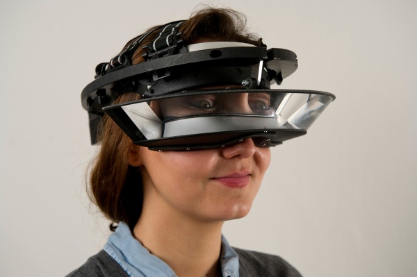
Carsten Holler, Upside down glasses
The goggles are based on an experiment carried out by George Stratton in the 1890s. While studying the perception in vision, the psychologist wore special glasses which inverted images up and down and left and right. He found that after 4 days wearing them continuously, his brain started to compensate, and he could see the world the right way up again.
Niklas Roy, We be cyborgs
“A cyborg, short for ‘cybernetic organism’, is a being with both organic and artificial parts.”
Niklas Roy writes about the workshop and the decision to use low-fi materials: "Regarding the cyborg building materials, we decided to leave computers and electronics out. Instead, we relied on post-apocalyptic plastic trash from one Euro shops, some medical gear and plenty of useful things from the hardware store around the corner"
We be cyborgs


Lucyandbart, Low tech plastic surgery
LucyandBart's a low – tech prosthetic way for human enhancement.
LUCYMCRAE

Soomi Park, The LED Eyelash
LINK to project
This project is brought into the world from a simple question: Why do women want larger and bigger eyes? Asian women tend to have stronger needs for bigger eyes as a standard of beauty, but relatively few of them are born with naturally big eyes. Those without big eyes can only look for alternative ways to make their eyes look prettier, i.e., larger, by using a repertoire of skills such as putting on makeup and wearing jewellery. Sometimes, the desires for bigger eyes can become almost obsessive, and many women opt for plastic surgery in order to make their dream come true: I call this, the fetish of Big Eyes.
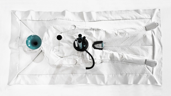
Requiem for a body, Soomi Park
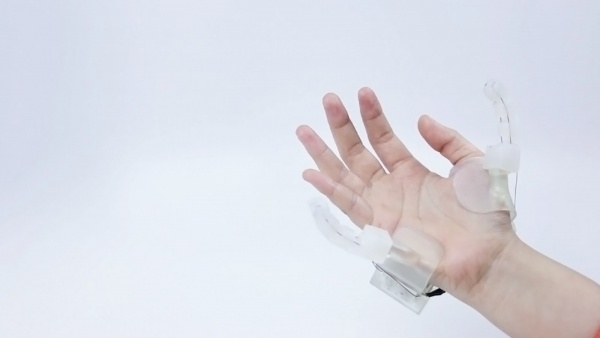
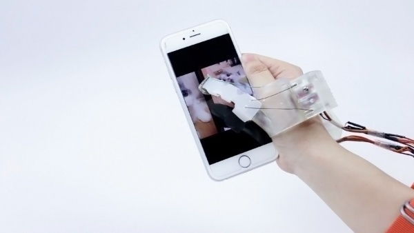
MIT prosthetics research [https://dam-prod.media.mit.edu/x/2017/11/04/p27-hu.pdf Soft Robotic Fingers
as Prosthetic Augmentation of the Hand]
Mis-using the body


Ann Hamilton, Face to Face
The artist uses her own mouth as a pinhole camera. The resulting images of faces and landscapes are strangely distorted, the curvature of her lips forming a shape that almost resembles an eye.
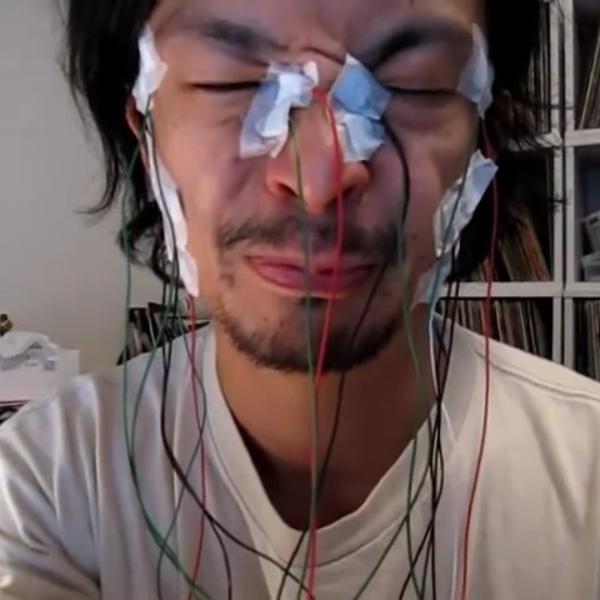
Arthur Elsenaar (1962) is a performance artist, former radio pirate and facial hacker from the Netherlands. Elsenaar is fascinated by the intimate relationship of electricity and the human body and is the originator of electro-facial choreography.
+ the work of Daito Manabe Daito Manabe
Exploding sensing
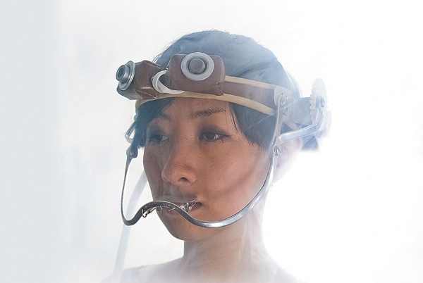
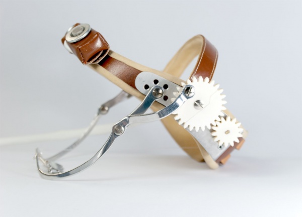
Susanna Hertrich
Jacobson’s Fabulous Olfactometer LINK to video
It is a sensorial prosthesis for extreme environments inspired by a sense organ called “Jacobson’s organ” that enables certain animals to sense odourless chemicals. Two sensors worn at the forehead register small particles and CO2 levels. When a dangerous threshold is overridden, gears are set in motion and the upper lip is pulled upwards to modify the wearer’s face similar to an animal behaviour called “flehmen”.
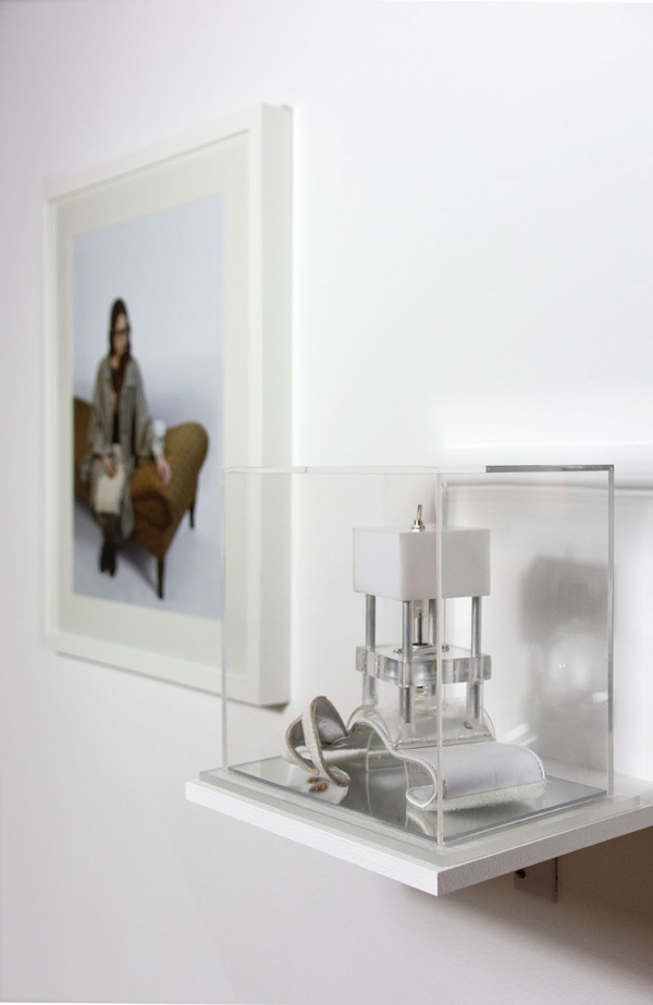
Automated Anchoring Armour
AAA holds a promise of continuous psychological intervention. The psychological treatment is worn as physical armour on the body and the skin becomes an interface to mental well-being. When a biosensor on the palm receives a signal of increased stress, the mechanism comes into action: A tap is repeatedly given to the forearm and thus aims to trigger a positive memory linked to this physical sensation. Its exaggerated physical shape amplifies the notion of a protective equipment.
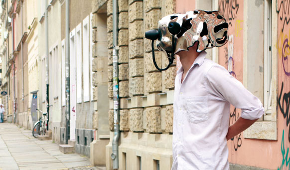
The Constitute studio, EYEsect
EYESECT is a wearable interactive installation that reflects an Out-of-Bodiment in an immersive way. By this it allows users to experience their environemts from new points of view. The world, as we perceive in reality and through media is aligned to binocular and stereoscopic vision of human beings. These omnipresent human-centristic perspectives and the critical debate about contemporary 3D Technology that only simulates real space and does not stimulate the lust for new and curiosity were the initial point from where the work on EYESECT began. The Question: “How do we not see” and the fascination for cybernetic – spirtual utopias, Science Fiction and bionic experiments lead to the development of one helmet device and two freely attachable camera eyes
more info here

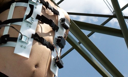
Gordan Savicic, Constraint City. The Pain of Everyday Life Link to Video
Savicics project is a city-intervention and digital art performance: A corset with high torque servo-motors and a WIFI-enabled game-console is worn as fetish object. The higher the wireless signal strength of nearby encrypted networks, the tighter the corset becomes.
A tool for discussion
Week 2: all those platforms and what to expect? Getting started with the Bare touch boards
All those platforms?
Bare boards / sound interface
Changing the sounds of the board
Week 3: Circuit Playground Express
Would you like to learn electronics, with an all-in-one board that has sensors and LEDs built in? Circuit Playground is an easy way to practice programming on real hardware. No soldering or sewing required!
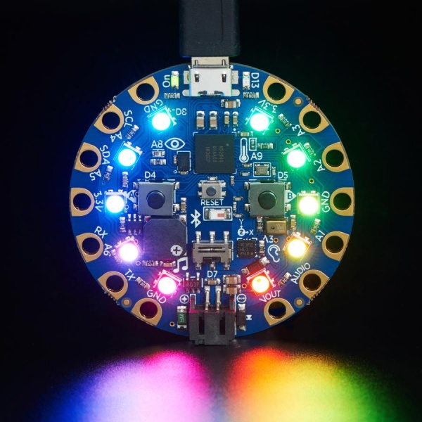
A complete inline guide HERE
Various ways to program
Using Arduino
We will follow the step by step guide HERE
Blink it
Simple switch
Light sensor
- Read the values
- control the lights
Add a servo
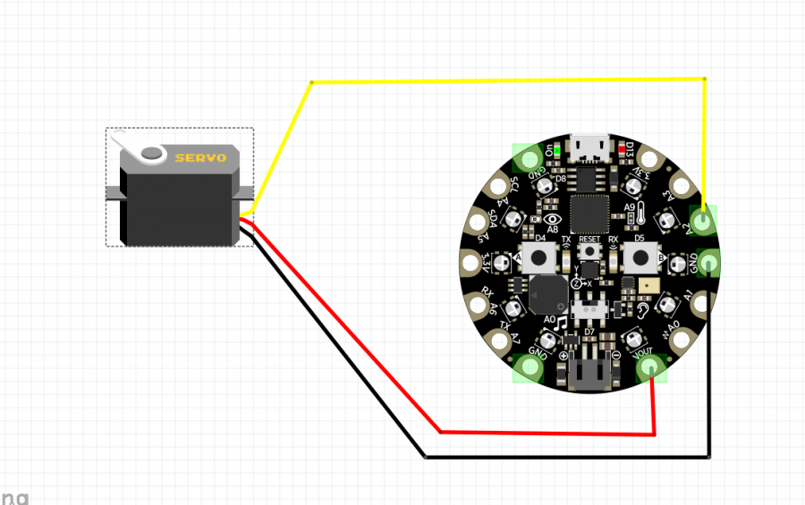
we will use the Sweep example from the Arduino IDE File-->Examples-->Servo-->Sweep
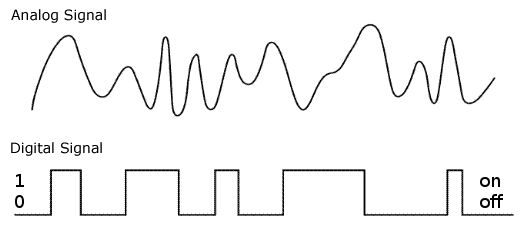
Analog vs Digital
Servo, servo who is the prettiest of all
[ME ME ME]
weeks 4 and 5:
Breathe in, breathe out
what is the Arduino
Hello everyone hello hello hello,
now what is an Arduino ...well...find a detailed introduction here [[1]]
Computer and processor are generic terms for the anything that can run a program, basically.
Controller or microcontroller usually refers to a simple processor that does only one task, like listening to sensors. In explaining microcontrollers, we’ll distinguish them from computers, which contain more powerful processors that can run an operating system.
Arduino is an open source physical computing platform based on a simple input/output (I/O) board and a development environment that implements the Processing language. Arduino can be used to develop standalone interactive objects
or can be connected to software on your computer.
The Arduino contains a microcontroller.
Most electronic devices today have a microcontroller at their core. Microcontrollers are optimized for control of general input and output.
What Is Physical Computing?
Physical Computing uses electronics to prototype new materials for ( in our case ) designers and artists.
Arduino is composed of two major parts: the Arduino board, which is the piece of hardware you work on when you build your objects; and the Arduino IDE, the piece of software you run on your computer. You use the IDE to create
a sketch (a little computer program) that you upload to the Arduino board. The sketch tells the board what to do.
In the meantime, HERE you can find ANYTHING about Arduino, including download the software
NOW,
The pins on your Arduino are the places where you connect wires to construct a circuit (probably in conjunction with a breadboard and some wire. They usually have black plastic ‘headers’ that allow you to just plug a wire right into the board. The Arduino has several different kinds of pins, each of which is labeled on the board and used for different functions.
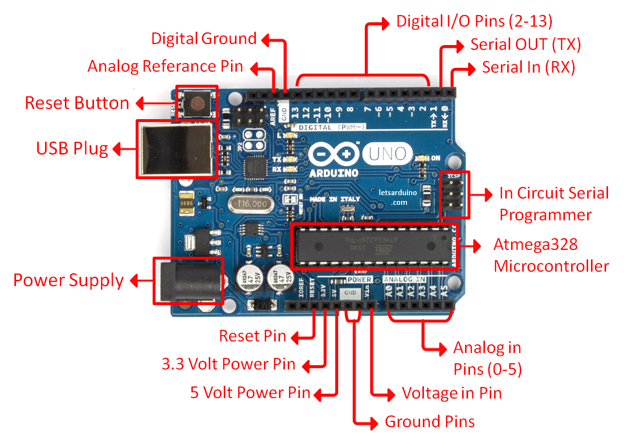
First things first
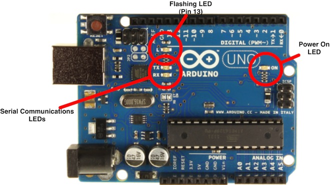
we start by figuring put if our Arduino is all good or it is somehow damaged ...it is a basic test to check and run a simple script at the same time.
Go to File ---> Examples ---> Basics --->Blink
so we have something like this
/*
  Blink
  Turns on an LED on for one second, then off for one second, repeatedly.

  Most Arduinos have an on-board LED you can control. On the Uno and
  Leonardo, it is attached to digital pin 13. If you're unsure what
  pin the on-board LED is connected to on your Arduino model, check
  the documentation at http://www.arduino.cc

  This example code is in the public domain.

  modified 8 May 2014
  by Scott Fitzgerald
 */


// the setup function runs once when you press reset or power the board
void setup() {
  // initialize digital pin 13 as an output.
  pinMode(13, OUTPUT);
}

// the loop function runs over and over again forever
void loop() {
  digitalWrite(13, HIGH);   // turn the LED on (HIGH is the voltage level)
  delay(1000);              // wait for a second
  digitalWrite(13, LOW);    // turn the LED off by making the voltage LOW
  delay(1000);              // wait for a second
}
GOOOD! lets dissect this
- commenting / one line and multiple lines
- setup
- loop
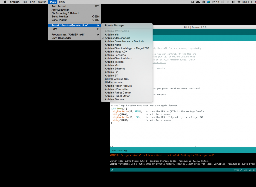
Choose board
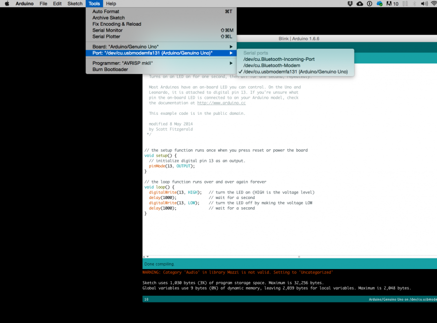
Choose port
Lets compile this
--- Press/ Click upper most left button, looks like a Tick. Observe the messages appearing in the bottom of the Arduino software window ( there must be a sentence Done Compiling
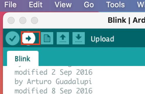
Lets upload this
And we should have a Blinking aka Flashing on board LED
Inputs and Outputs
Like mentioned earlier - μControllers are optimized for control of general input and output. What are those two exactly.
Analog ( we have six of them in the Uno): The area of pins under the ‘Analog In’ label (A0 through A5 on the UNO) are Analog In pins. These pins can read the signal from an analog sensor (like a temperature sensor) and convert it into a digital value that we can read.
Digital (seven on the Uno): Across from the analog pins are the digital pins (0 through 13 on the UNO). These pins can be used for both digital input (like telling if a button is pushed) and digital output (like powering an LED).
Sensors
Digital Sensors
Digital sensors are the sensors that gives 2 state (on/off, 5V/0V). You will connect them to digital Pins and set it as INPUT.
Digital data consists exclusively of 0s and 1s .
For example, consider a push button switch. This is one of the simplest forms of sensors. It has two discrete values. It is on, or it is off. Other 'discrete' sensors might provide you with a binary value.
Another example of a digital sensor is an accelerometer, which sends a series of data points (speed, direction, and so on) to the Arduino. Usually digital sensors need a chip in the sensor to interpret the physical data.
Analog Sensors
Analog sensors on the other hand, gives range. You connect this types of Analog sensors to Analog Input pins which is measuring the incoming voltage between 0V-5V*. Arduino converts this incoming voltage into the number between 0-1023.
Analog data is transmitted as a continuous signal, almost like a wave. In other words, an analog sensor doesn’t send a burst of 1s and 0s like digital sensors do; instead, the sensor modulates a continuous signal to transmit data.
Microcontrollers are capable of detecting binary signals: is the button pressed or not? These are digital signals. When a microcontroller is powered from five volts, it understands zero volts (0V) as a binary 0 and a five volts (5V) as a binary 1. The world however is not so simple and likes to use shades of gray. What if the signal is 2.72V? Is that a zero or a one? We often need to measure signals that vary; these are called analog signals. A 5V analog sensor may output 0.01V or 4.99V or anything inbetween. Luckily, nearly all microcontrollers have a device built into them that allows us to convert these voltages into values that we can use in a program to make a decision.
An Analog to Digital Converter (ADC) is a very useful feature that converts an analog voltage on a pin to a digital number. By converting from the analog world to the digital world, we can begin to use electronics to interface to the analog world around us.
Not every pin on a microcontroller has the ability to do analog to digital conversions. On the Arduino board, these pins have an ‘A’ in front of their label (A0 through A5) to indicate these pins can read analog voltages.
ADCs can vary greatly between microcontroller. The ADC on the Arduino is a 10-bit ADC meaning it has the ability to detect 1,024 (210) discrete analog levels. Some microcontrollers have 8-bit ADCs (28 = 256 discrete levels) and some have 16-bit ADCs (216 = 65,536 discrete levels).
case study: Stretch Sensor
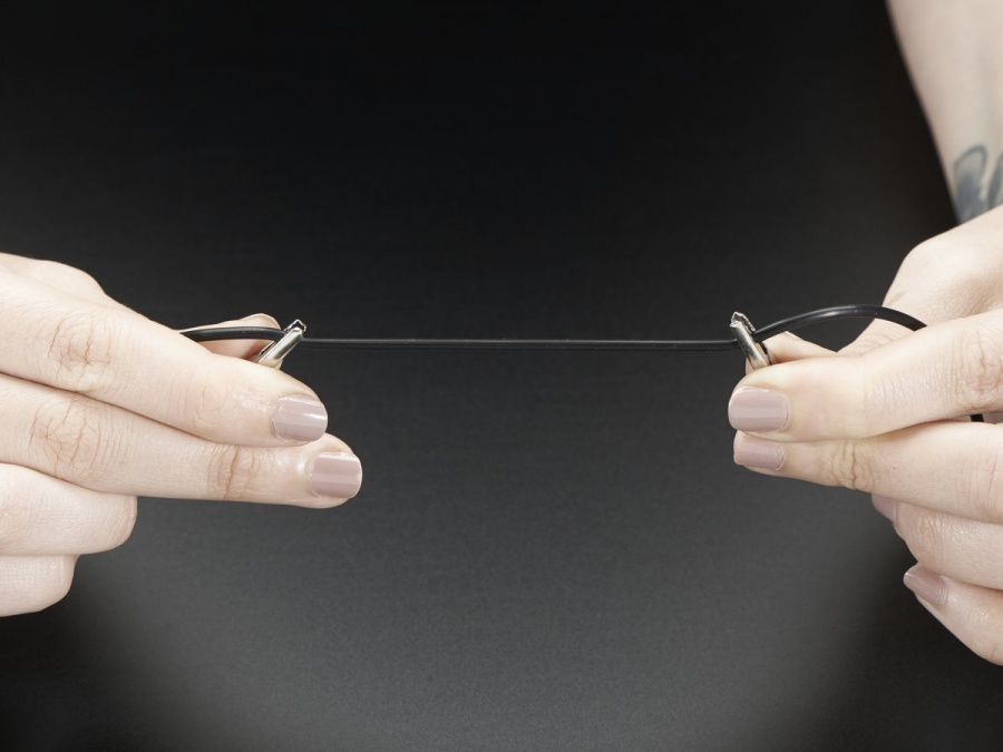
As a main actor of today we will take the conductive rubber.
Hooked up to two alligator clips we create a simple resistive sensor.
Analog Voltage Reading Method
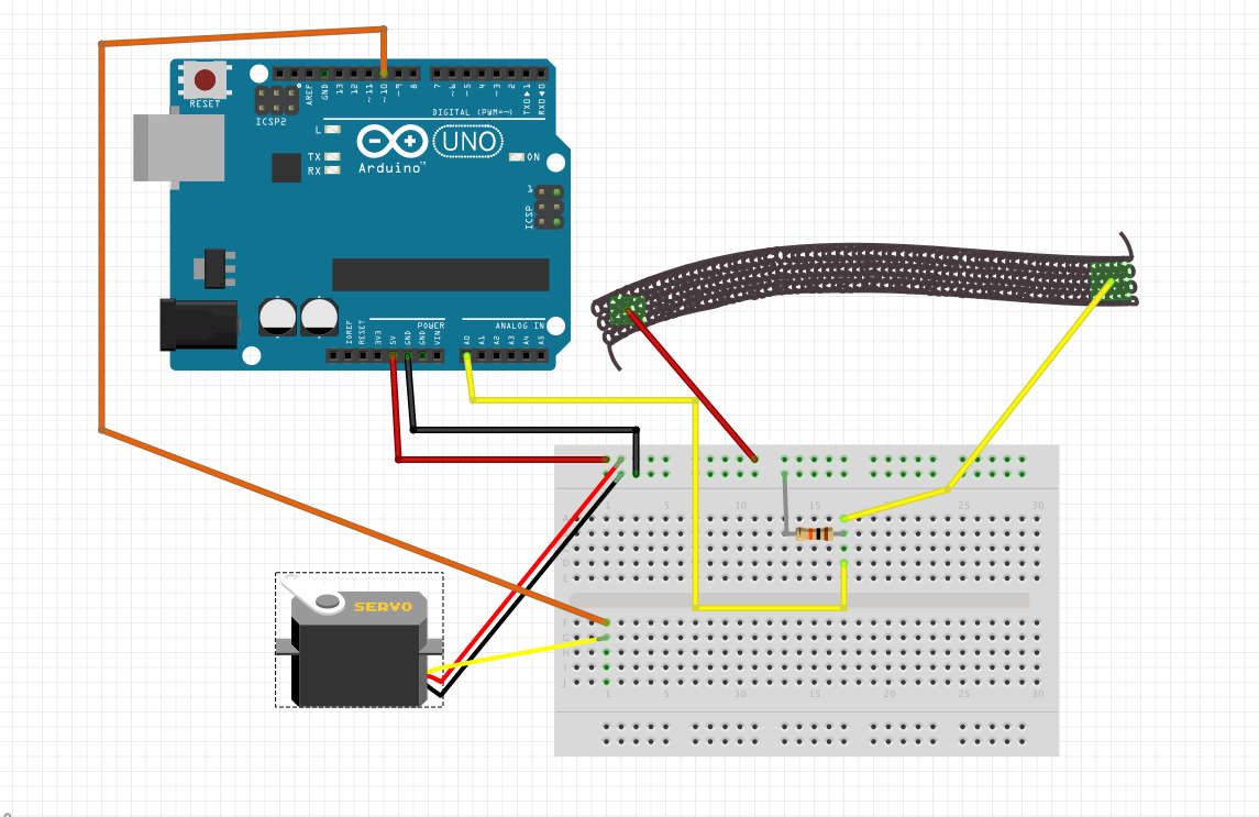
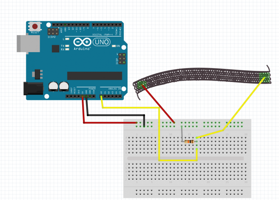
The easiest way to measure a resistive sensor is to connect one end to Power and the other to a pull-down resistor to ground. Then the point between the fixed pulldown resistor and the variable resistor ( conductive rubber) is connected to the analog input of a microcontroller such as the Arduino.
OK, wait...the BREADBOARD
OK, first, what's with the name....bread board? Bread, like in food?
Well yes, kind of.
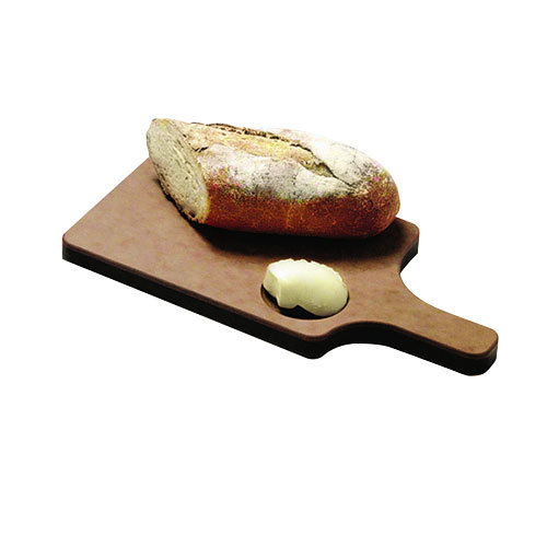
This terminology goes way back in the days.
Generally, you would mount electronic components to a piece of wood (the actual "breadboard"), and do all the wiring with point-point wire and the components just hanging between the various devices.
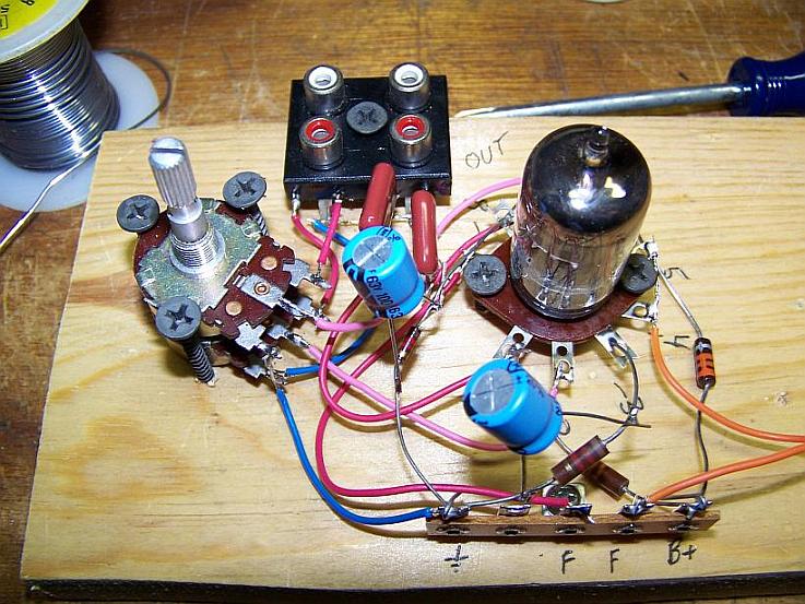
The story goes that an engineer had an idea for a vacuum tube device late one night. Looking around the house, the only base for his prototype that he found was indeed his wife's breadboard, from the breadbox.
A video by the Make magazine people
Ok, but why do we need to breadboard?
Well, they are useful for making temporary circuits and prototyping, and they require absolutely no soldering.
Prototyping is the process of testing out an idea by creating a preliminary model from which other forms are developed or copied, and it is one of the most common uses for breadboards.
The best way to explain how a breadboard works is to take it apart and see what’s inside.
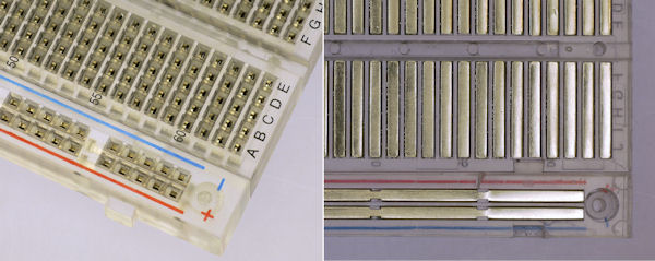
connections lines are connected like this
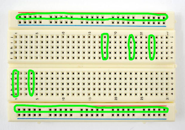
So lets do it
get some data from it
const int sensor= A0;


// the setup runs once when you press reset or start the arduino:
void setup() {
// initialize serial communication at 9600 bits per second:
  Serial.begin(9600);


}

// the loop runs over and over again:
void loop() {
  int sensorValue = analogRead(sensor); // read the voltage from the voltage divider (sensor plus resistor)
  Serial.println (sensorValue); //print the sensorValue into the Serial Monitor
  delay(1);        // delay in between reads for stability

}
It's alive
now lets add an Output
//including the servo library
#include <Servo.h>

Servo myservo;  // create servo object to control a servo
// twelve servo objects can be created on most boards

void setup() {


Serial.begin(9600); // initialize serial communication at 9600 bits per second:
myservo.attach(10);  // attaches the servo on pin 10 to the servo object
}

void loop() {

int sensor;
int degrees;
sensor = analogRead(A0); // read the voltage from the voltage divider (sensor plus resistor)

degrees = map(sensor, 200, 150, 0, 90);
// the first two numbers are the sensor values for unstretched and stretched
// the second two numbers are the degree readings we'll map that to (0 to 90 degrees)
// the above numbers are just an example, your sensor's values will vary
// to improve the accuracy, run the program, note your sensor's analog values
// when it's calm and stretched, and insert those values into the above function.

myservo.write(degrees);// sets the servo position according to the scaled value

delay(5); // waits for the servo to get there

//for debug use
// print out the result

Serial.print("analog input: ");
Serial.print(sensor);
Serial.print(" degrees: ");
Serial.println(degrees);

delay(5);// pause before taking the next reading

}
Some calibration
#include <Servo.h>


// These constants won't change:
const int sensorPin = A0;    // pin that the sensor is attached to
Servo myservo;  // create servo object to control a servo

// variables:
int sensorValue = 0;         // the sensor value
int sensorMin = 1023;        // minimum sensor value
int sensorMax = 0;           // maximum sensor value

void setup() {
 Serial.begin(9600);
 myservo.attach(10); // attaches the servo on pin 10 to the servo object

  // turn on LED to signal the start of the calibration period:
  pinMode(13, OUTPUT);
  digitalWrite(13, HIGH);

  // calibrate during the first five seconds
  while (millis() < 5000) {
    sensorValue = analogRead(sensorPin);

    // record the maximum sensor value
    if (sensorValue > sensorMax) {
      sensorMax = sensorValue;
    }

    // record the minimum sensor value
    if (sensorValue < sensorMin) {
      sensorMin = sensorValue;
    }
  }
digitalWrite(13, LOW);
}


void loop() {


  // read the sensor:
  sensorValue = analogRead(sensorPin);

  // apply the calibration to the sensor reading
  sensorValue = map(sensorValue, sensorMin, sensorMax, 0, 180);

  // in case the sensor value is outside the range seen during calibration
  sensorValue = constrain(sensorValue, 0, 180);

 Serial.println(sensorValue);
 myservo.write(sensorValue);// sets the servo position according to the scaled value

delay(5); // waits for the servo to get there

}
