Motors: Introduction and Types
This is a brief introduction into motor types and ways to control them. Do you want to know more about how the motors work electrically, get an intuition on how Volt, Ampère and Ohm can be understood, and how your motor can be used to generate electricity? Then head to Late Night Soldering: Wind.
DC Motors
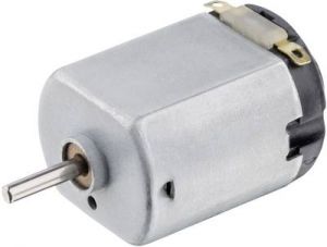
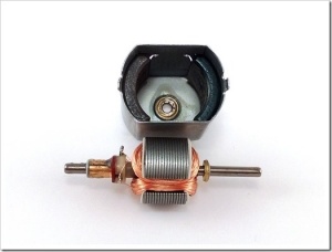
DC (Direct Current) motors are two wire (power & ground), continuous rotation motors. When you supply power, a DC motor will start spinning until that power is removed. Most DC motors run at a high RPM (revolutions per minute).
Some examples of projects using DC motors:
https://www.youtube.com/embed/cBxumuXjS78?si=alyzXXgnvcsXXZpd
https://www.youtube.com/embed/g__Q6zy5K4U?si=PUVxzrq945sh6j0X
Power
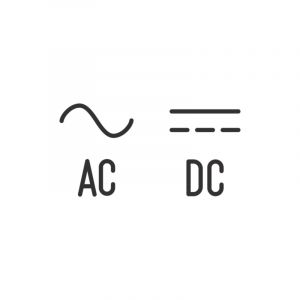
DC motors use direct current, which is different from alternating current (AC). Power from the wall is alternating current, not direct current, so don't directly plug your DC motor into the wall.
To power your motor, you'll need some kind of power supply. To find the right power supply for your motor, first check if the power supply is AC or DC. Often power supplies have some kind of symbol to indicate this.
Afterwards check the motor rating on your motor. In our case we used the geared motor that's in the Arduino kit. By looking up information about the motor online we found that the voltage rating is is 3-6V.
Then we'll have to check how many Amps our motor will need. Sometimes this is on the motor as well.
No power rating? If your not sure how many Volts and Amps your motor needs, it's best to check with a lab bench power supply (there is one at the Interaction Station). Start with a low voltage and crank it up until it runs smooth but doesn't get super hot. You can also see how many Amps the motor uses. With this information, you can look for the right power supply for your motor.
If you want to check the Amps without the lab bench power supply, you can use a multimeter.
Direction & Polarity
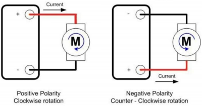
DC motors can rotate both clockwise and counter clockwise. You can change the direction of your motor by changing the polarity.
Connection
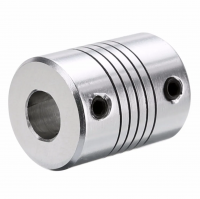
To connect other thing to your motor shaft, you'll need some kind of connecting piece. A common way to do this is by using a motor coupling. Check the diameter of your motor to see if you can find the right one.
Do you want your moving project to move in a certain way? Maybe information on Mechanisms can help you out.
Torque
Most DC motors spin at a high speed with relatively low torque. For your project, it might be necessary to increase the torque by slowing down your motor. This can be done by using belt drives or gears and connecting them to the shaft of the motor. There are a lot of 3D printed project that you can download, so see if you can find one for your motor. Here is an example:
https://www.thingiverse.com/thing:3600574
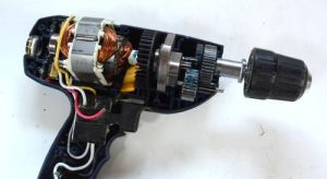
Some motors already have a gearbox. These are called geared DC motors. A motor that is commonly used with gears is the wiper motor. This motor also has a 8mm thread and sometimes comes with a mechanism, so they are quite versatile. Geared motors can also be found in other object, like in drills. Here you can see a picture of a drill motor:
Switch Control
If you're making some kind of mechanical installation or kinetic artwork, it might be handy to be able to turn on and off your motor electronically. For this we can use an Arduino and a relay board. To see how to do this, go to the following page:
Using a relay for motor control
Speed Control
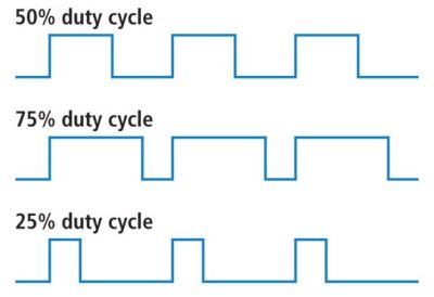
Do you just want to slow down your project but don't necessarily need more torque? Then you can try slowing down your motor using pulse width modulation (PWM), a technique of rapidly pulsing the power on and off. The percentage of time spent cycling the on/off ratio determines the speed of the motor, e.g. if the power is cycled at 50% (half on, half off), then the motor will spin at half the speed of 100% (fully on). Each pulse is so rapid that the motor appears to be continuously spinning with no stuttering!
At the Interaction Station, we have two options that can be used to control motor speed with PWM.
1: Adafruit Motor Shield V2: - Up to 4 DC motors, forward and reverse). - Max 12V and 1,2A for each motor.
2: Driving DC motors with the L298N: - Up to 2 DC motors, forward and reverse. - Max 46V and 2A for each motor.
You can also make a simple motor control circuit using a MOSFET, like with the IRL540. These can only go one way (only forward), but are cheap and you can make a compact custom design for your project. For more information see:
https://www.instructables.com/ArduinoMicrocontroller-MOSFET/
When you use pulse width modulation, the electricity turn on and off at a certain frequency. Sometimes you can hear this frequency. It sounds like a high pitched beep. Do you want to change this frequency to another or to something inaudible?
Go to Pulse Width Modulation frequency control
Servo motors
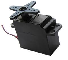
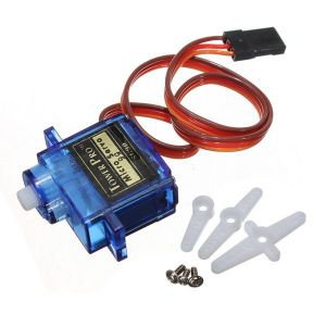
Servo motors are basically more flavoured Dc motors.
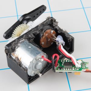
They are generally an assembly of four things: a DC motor, a gearing set, a control circuit and a position-sensor (usually a potentiometer).
The position of servo motors can be controlled more precisely than those of standard DC motors, and they usually have three wires (power, ground & control). Power to servo motors is constantly applied, with the servo control circuit regulating the draw to drive the motor.
Servo motors do not rotate freely like a standard DC motor. Instead the angle of rotation is limited to 180 Degrees back and forth. Servo motors receive a control signal that represents an output position and applies power to the DC motor until the shaft turns to the correct position, determined by the position sensor.
PWM is used for the control signal of servo motors. However, unlike DC motors it’s the duration of the positive pulse that determines the position, rather than speed, of the servo shaft. A neutral pulse value depending on the servo (usually around 1.5ms) keeps the servo shaft in the center position. Increasing that pulse value will make the servo turn clockwise, and a shorter pulse will turn the shaft anticlockwise. The servo control pulse is usually repeated every 20 milliseconds, essentially telling the servo where to go, even if that means remaining in the same position.
Inside
Internally, the mechanism of a servo motor uses a potentiometer attached to the rotating shaft to sense the position. It measures the width of the incoming pulse and applies current to the motor to turn the shaft, until the potentiometer indicates that the position corresponds to the incoming pulse width. This is a form of feedback control. The motor has received the desired position from the pulse width, and the actual shaft position is fed back to the circuit via the potentiometer. It compares the desired value to the actual value and drives the motor in the direction that causes actual to match desired.
Example of an art project using servo motors:
How to control a servo
The wiki contains some more information on servo's and how to control them:
- Servo motor: For more basic information on how to control a servo motor with a microcontroller, see Servo motor.
- MoreAboutServo: If you want to use multiple servo's or/and would like to make some kind of mechanism that you operate with the servo, head to MoreAboutServo
- Make a drawing machine and a Grabber robot with Arduino: If you want to make some kind of moving arm, Make a drawing machine and a Grabber robot with Arduino might help you.
Stepper motors
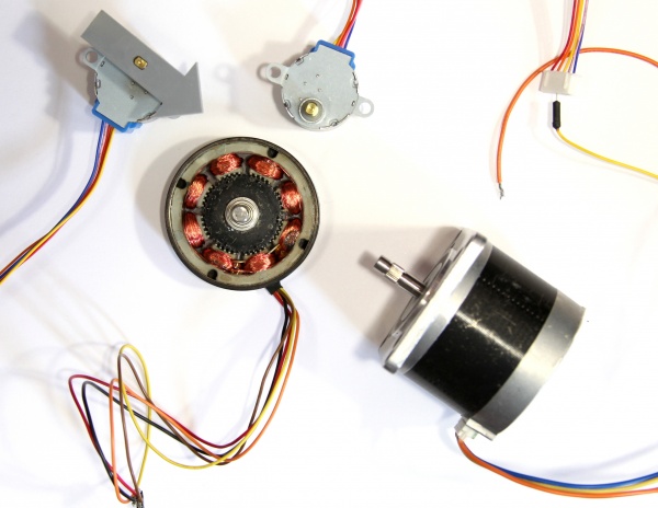
A stepper motor is essentially a servo motor that uses a different method of motorization. Where a servo motor uses a continuous rotation DC motor and integrated controller circuit, stepper motors use multiple toothed electromagnets arranged around a central gear to define position.
Stepper motors require an external control circuit or micro controller (for instance a Raspberry Pi or Arduino) to individually energize each electromagnet and make the motor shaft turn. When electromagnet ‘A’ is powered it attracts the gear’s teeth and aligns them, slightly offset from the next electromagnet ‘B’. When ‘A’ is switch off, and ‘B’ switched on, the gear rotates slightly to align with ‘B’, and so on around the circle, with each electromagnet around the gear energizing and de-energizing in turn to create rotation. Each rotation from one electromagnet to the next is called a "step", and thus the motor can be turned by precise predefined step angles through a full 360 Degree rotation.
Stepper motors are available in two varieties; unipolar or bipolar. Bipolar motors are the strongest type of stepper motor and usually have four or eight leads. They have two sets of electromagnetic coils internally, and stepping is achieved by changing the direction of current within those coils. Unipolar motors, identifiable by having 5,6 or even 8 wires, also have two coils, but each one has a center tap. Unipolar motors can step without having to reverse the direction of current in the coils, making the electronics simpler. However, because the center tap is used to energize only half of each coil at a time they typically have less torque than bipolar.
The design of the stepper motor provides a constant holding torque without the need for the motor to be powered and, provided that the motor is used within its limits, positioning errors don't occur, since stepper motors have physically predefined stations.
How to control a stepper motor
At the Interaction Station, we use the Adafruit Motorshield V2 as a stepper driver. You can find instruction on how to control your stepper here: Arduino & Stepper motors
Solenoids
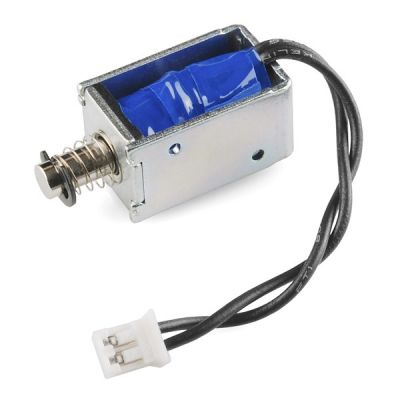
Electric solenoids work on similar electromagnetic principles to those of DC motors, however, solenoids can use the magnetic energy to push or pull something rather than turn it. Solenoids are found in paintball guns, pinball machines, printers, valves and even automobiles.
A Solenoid is a coil that when energised, produces a controlled magnetic field down through its centre. By placing a magnetic armature inside that field, the armature can move in or out of the coil.
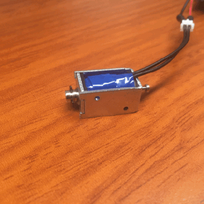
Example of a project using solenoids:
Extra Resources
Stepper motors, controlled via a micro controller are easy to follow at what rpm they operate, and to be adjusted AND with dc motors, it is a fixed rpm with a small torque, at which the motor operates, and in order to adjust this, gear systems, pulleys .....there is more.
Making things move is a book, very useful, please download it and look especially into Forces, Friction, and Torque (Oh My!) starting page 73 and then The Guts: Bearings, Couplers, Gears, Screws, and Springs page 189 till the end. But also check out the website for useful bits and pieces.
!!! WATCH THIS / very nice video from the Prelinger Archives, the motor part starts at 06:12
How to convert the motors movement into the desired one? Check out the Simple Mechanisms page.
